Allied Telesis AT-FS705LE Installation Manual
10/100base ethernet switch
Hide thumbs
Also See for AT-FS705LE:
- Installation manual (60 pages) ,
- Datasheet (2 pages) ,
- Datasheet (2 pages)
Table of Contents
Advertisement
Quick Links
Download this manual
See also:
Installation Manual
Advertisement
Table of Contents

Related Manuals for Allied Telesis AT-FS705LE


Summary of Contents for Allied Telesis AT-FS705LE
-
Page 1: Installation Guide
AT-FS705LE 10/100Base Ethernet Switch Installation Guide PN 613-50138-00 Rev C... - Page 2 Copyright 2002 Allied Telesyn, Inc. 960 Stewart Drive Suite B, Sunnyvale CA USA 94086 All rights reserved. No part of this publication may be reproduced without prior written permission from Allied Telesyn, Inc. Ethernet is a registered trademark of Xerox Corporation. All other product names, company names, logos or other designations mentioned herein are trademarks or registered trademarks of their respective owners.
-
Page 3: Electrical Safety And Emission Statement
408-730-0950 Declares that the product: Ethernet Switch Model Number: AT-FS705LE This product complies with FCC Part 15B, Class B Limits: This device complies with part 15 of the FCC Rules. Operation is subject to the following two conditions: (1) This... - Page 4 Connect the equipment into an outlet on a circuit different from that to which the receiver is connected. Consult the dealer or an experienced radio/TV technician for help. Changes and modifications not expressly approved by the manufacturer or registrant of this equipment can void your authority to operate this equipment under Federal Communications Commission rules.
- Page 5 Belangrijk: Appendix A bevat vertaalde veiligheidsopmerkingen voor het installeren van deze apparatuur. Wanneer u de ziet, raadpleeg Appendix A voor vertaalde veiligheidsinstructies in uw taal. Important: L'annexe A contient les instructions de sécurité relatives à l'installation de cet équipement. Lorsque vous voyez le symbole , reportez-vous à...
-
Page 7: Table Of Contents
E-mail Support ........xi Returning Products ........xii FTP Server............. xiii For Sales or Corporate Information ..... xiii Tell Us What You Think ....... xiii AT-FS705LE Fast Ethernet Switch ..1 Overview ............1 Features ............2 Physical Description........3 Ports 1 Through 4........3 Port 5 and the Uplink Port ......4 Status LEDs ..........5... - Page 8 Network Topologies .........6 Installing the Switch ........8 Verifying the Package Contents ....8 Selecting a Site .........9 Reviewing Safety Guidelines ....10 Installing the Switch on a Desktop ..12 Installing the Switch on a Wall ....14 Warranty Registration ........16 Troubleshooting ..........16 Technical Specifications .........18 Physical............18 Temperature ..........18 Electrical Rating........18...
-
Page 9: Welcome To Allied Telesyn
Welcome to Allied Telesyn This guide contains instructions on how to install the AT-FS705LE Ethernet Switch. Where to Find Web-based Guides The Allied Telesyn web site at www.alliedtelesyn.com offers you an easy way to access the most recent documentation, software, and technical information for all of our products. -
Page 10: Contacting Allied Telesyn Technical Support
Caution Cautions informs you that performing or omitting a specific action may result in equipment damage or loss of data. Warning Warnings informs you that performing or omitting a specific action may result in bodily injury. Contacting Allied Telesyn Technical Support You can contact Allied Telesyn technical support online or by telephone or e-mail. -
Page 11: Telephone Support
AT-FS705LE Installation Guide Telephone Support For technical support by phone, contact Allied Telesyn at one of the following locations: Americas Germany United States, Canada, Switzerland, Austria, Eastern Mexico, Central America, Europe South America Tel: (+49) 30-435-900-126 Tel: 1 (800) 428-4835... -
Page 12: Returning Products
Returning Products Products for return or repair must first be assigned a Return Materials Authorization (RMA) number. A product sent to Allied Telesyn without a RMA number will be returned to the sender at the sender’s expense. To obtain an RMA number, contact Allied Telesyn’s Technical Support at one of the following locations: North America... -
Page 13: Ftp Server
AT-FS705LE Installation Guide FTP Server If you need management software for an Allied Telesyn managed device and you know the file name of the software, you can download the software by connecting directly to our FTP server at ftp:alliedtelesyn.com. At login, enter ‘anonymous’... -
Page 15: At-Fs705Le Fast Ethernet Switch
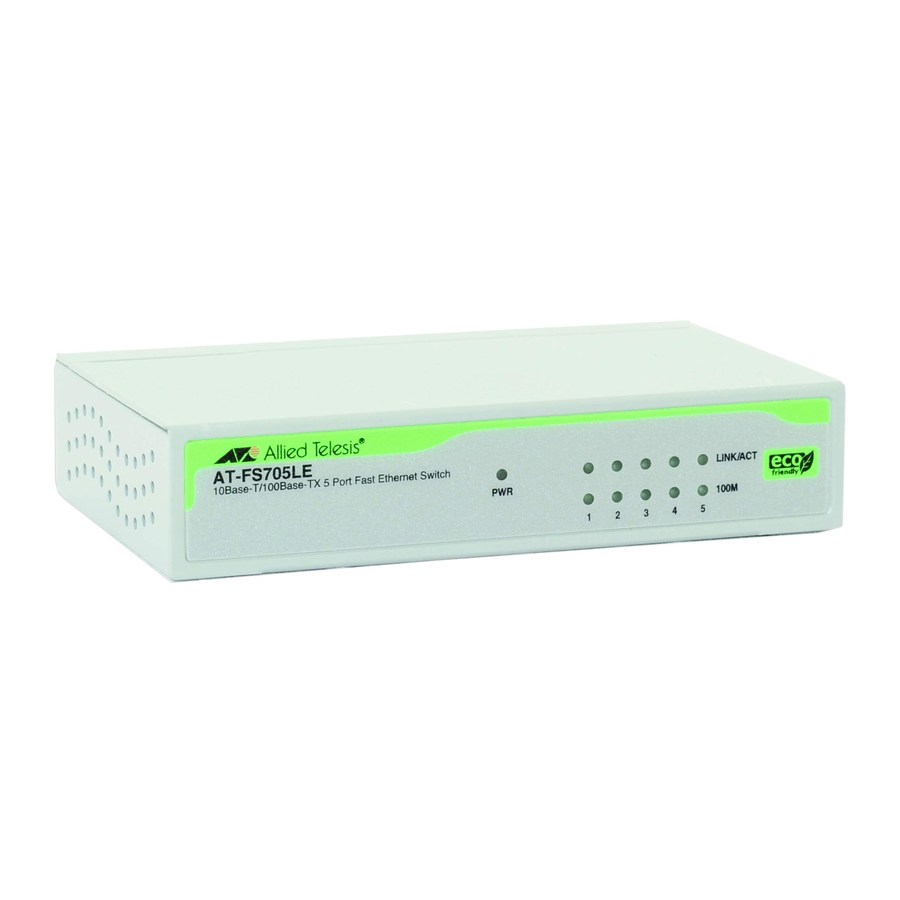
AT-FS705LE Fast Ethernet Switch Overview The AT-FS705LE Ethernet Switch is a 10Base-T/100Base-TX unmanaged switch. The switch provides you with a simple, cost-effective solution for Ethernet switching between end- nodes operating at either 10 Mbps or 100 Mbps. Figure 1 and Figure 2 show the front and back panels of the switch. -
Page 16: Features
Figure 2 AT-FS705LE Back Panel Features The AT-FS705LE switch has the following features: Five auto-negotiating 10/100 Mbps twisted pair ports with RJ-45 connectors One Uplink port for connecting the AT-FS705LE switch to another switch or hub without a crossover cable IEEE 802.3 and IEEE 802.3u compliant... -
Page 17: Physical Description
AT-FS705LE Installation Guide Physical Description The physical description for the switch includes: Ports 1 through 4 Port 5 and the Uplink port LEDs Power supply Ports 1 Through 4 Ports 1 through 4 can operate at either 10 Mbps or 100 Mbps and in either half- or full-duplex mode. -
Page 18: Port 5 And The Uplink Port
Port 5 and the Uplink Port Port 5 and the Uplink port allow you to connect an additional workstation to the switch or interconnect the switch with another switch or hub, without the use of a crossover cable. If you need to connect an additional workstation to the switch, use Port 5, which is configured as MDI-X. -
Page 19: Status Leds
AT-FS705LE Installation Guide Status LEDs Refer to Table 1 for a description of the switch’s LEDs. Table 1 LEDs LEDs Color Description Green Power is applied to the switch. 100M Green The port is operating at 100 Mbps. The port is operating at 10 Mbps. -
Page 20: Power Supply
Power Supply The AT-FS705LE switch uses an external AC/ DC power adapter that comes standard with the switch. Network Topologies Figure 3 illustrates a network that consists of one AT-FS705LE switch used to interconnect four workstations and a server. In this configuration, the Uplink port is not used. - Page 21 Figure 4 illustrates a network of two AT-FS705LE switches that have been interconnected using the Uplink ports on the two units. Using the Uplink ports eliminates the need for a crossover cable to interconnect the switches. Figure 4 Multiple AT-FS705LE Switch Topology...
-
Page 22: Installing The Switch
Make sure the following items are included in your package. If any item is missing or damaged, contact your Allied Telesyn sales representative for assistance. An AT-FS705LE Ethernet Switch An external power adapter Four self-adhesive rubber feet This installation guide... -
Page 23: Selecting A Site
AT-FS705LE Installation Guide Selecting a Site Be sure to observe the following requirements when choosing a site for your switch. Make sure you are placing the switch in a dust-free and moisture-free environment. Do not block the ventilation openings on the unit. -
Page 24: Reviewing Safety Guidelines
Observe the following cabling specifications: Connector Type of Maximum Ports Type Cable Distance 1 through 5 RJ-45 Category 5 100 m (328 ft) Uplink RJ-45 Category 5 100 m (328 ft) Reviewing Safety Guidelines Please review the following safety guidelines before installing the switch. - Page 25 AT-FS705LE Installation Guide Caution Air vents: The air vents must not be blocked on the unit and must have free access to the room ambient air for cooling. Caution Operating Temperature: This product is designed for a maximum ambient temperature of 40°C.
-
Page 26: Installing The Switch On A Desktop
Installing the Switch on a Desktop To use the switch on the desktop, perform the following procedure. To wall-mount the switch, refer to “Installing the Switch on a Wall” on page 14. 1. Remove all the items from the shipping package and store the packaging material in a safe place. - Page 27 AT-FS705LE Installation Guide 6. Attach the data cables to the switch ports. Do not use a crossover cable to connect workstations or servers to ports 1 through 5. Do not use a crossover cable to connect another switch or hub to the Uplink port.
-
Page 28: Installing The Switch On A Wall
Installing the Switch on a Wall For wall-mount installation, you can position the switch vertically or horizontally using the keyhole cutouts in the bottom of the switch. 1. If previously attached, remove the rubber feet, data cables, and the DC power cord from the switch. - Page 29 1 through 5. Do not use a crossover cable to connect another AT-FS705LE switch to the Uplink port. Note You can use either Port 5 or the Uplink port, but you cannot use both simultaneously.
-
Page 30: Warranty Registration
Check to be sure that the power adapter is securely connected to the power source and to the DC connector on the front of the AT-FS705LE switch. Check to be sure that the power outlet has power by connecting another device to it. - Page 31 AT-FS705LE Installation Guide If the LINK/ACT LED is OFF, do the following: Check to be sure that the end-node connected to the port on the switch is powered ON. If the end-node is OFF, power the unit ON. Check that the cable is securely connected to the port on the switch and on the end- node.
-
Page 32: Technical Specifications
Technical Specifications Physical Dimensions: W x D x H 100 x 78.5 x 26 mm (3.93 x 3.09 x 1.02 in) Temperature Maximum Operating 0° to 40° C Maximum Storage -25° to 70° C Operating Humidity 10% to 90% Relative Humidity Electrical Rating Input Supply Voltage:... -
Page 33: Translated Safety And Emission Information
Appendix A Translated Safety and Emission Information Important: This appendix contains multiple- language translations for the safety statements in this guide. Wichtig: Dieser Anhang enthält Übersetzungen der in diesem Handbuch enthaltenen Sicherheitshinweise in mehreren Sprachen. Vigtigt: Dette tillæg indeholder oversættelser i flere sprog af sikkerhedsadvarslerne i denne håndbog. - Page 34 Importante: questa appendice contiene traduzioni in più lingue degli avvisi di sicurezza di questa guida. Viktig: Dette tillegget inneholder oversettelser til flere språk av sikkerhetsinformasjonen i denne veiledningen. Importante: Este anexo contém traduções em vários idiomas das advertências de segurança neste guia.
- Page 35 AT-FS705LE Installation Guide Standards: This product meets the following standards: U.S. Federal Communications Commission Declaration Of Conformity Manufacture Name: Allied Telesyn, Inc. Manufacture Address: 960 Stewart Drive, Suite B Sunnyvale, CA 94086 USA Manufacture Telephone: 408-730-0950 Declares that the product:...
- Page 36 Changes and modifications not expressly approved by the manufacturer or registrant of this equipment can void your authority to operate this equipment under Federal Communications Commission rules. Industry Canada This Class B digital apparatus meets all requirements of the Canadian Interference-Causing Equipment Regulations. Cet appareil numérique de la classe B respecte toutes les exigences du Règlement sur le matériel brouilleur du Canada.
- Page 37 AT-FS705LE Installation Guide USA/Canada: Use a UL Listed/CSA Certified AC adapter of DC 7.5V, 1A. Normen: Dieses Produkt erfüllt die Anforderungen der nachfolgenden Normen. Hochfrequenzstörung EN55022 Klasse B Warnung: Bei Verwendung zu Hause kann dieses Produkt Funkstörungen hervorrufen. In diesem Fall müßte der Anwender angemessene Gegenmaßnahmen ergreifen.
- Page 38 Standarder: Dette produkt tilfredsstiller de følgende standarder. Radiofrekvens forstyrrelsesemission: EN55022 Klasse B Advarsel: I et hjemligt miljø kunne dette produkt forårsage radio forstyrrelse. Bliver det tilfældet, påkræves brugeren muligvis at tage tilstrækkelige foranstaltninger. Immunitet EN50082-1 1997 Elektrisk sikkerhed UL 1950, EN60950, VCCI Class B Sikkerhed Advarsel: Den strømførende ledning bruges til at...
- Page 39 AT-FS705LE Installation Guide Eisen: Dit product voldoet aan de volgende eisen. RFI Emissie EN55022 Klasse B Waarschuwing: Binnenshuis kan dit product radiostoring veroorzaken, in welk geval de gebruiker verplicht kan worden om gepaste maatregelen te nemen. Immuniteit EN50082-1 1997 Electrische Veiligheid...
- Page 40 Normes: ce produit est conforme aux normes de suivantes. Emission d’interférences radioélectriques EN55022 Classe B Mise En Garde: Dans un environnement domestique, ce produit peut provoquer des interférences radioélectriques. Auquel cas, l’utilisateur devra prendre les mesures adéquates. Immunité EN50082 - 1 1997 Sécurité...
- Page 41 AT-FS705LE Installation Guide Standardit: Tämä tuote on seuraavien standardien mukainen. Radioaaltojen häirintä EN55022 Luokka B Varoitus: Kotiolosuhteissa tämä laite voi aiheuttaa radioaaltojen häiröitä, missä tapauksessa laitteen käyttäjän on mahdollisesti ryhdyttävä tarpeellisiin toimenpiteisiin. Kestävyys EN50082-1 1997 Sähköturvallisuus UL 1950, EN60950, VCCI Class B Turvallisuus Huomautus: Virtajohtoa käytetään...
- Page 42 Standard: Questo prodotto è conforme ai seguenti standard. Emissione RFI (interferenza di radiofrequenza) EN55022 Classe B Avvertenza: in ambiente domestico questo prodotto potrebbe causare radio interferenza. In questo caso potrebbe richiedersi all’utente di prendere gli adeguati provvedimenti. Immunità EN50082-1 1997 Sicurezza elettrica UL 1950, EN60950, VCCI Class B...
- Page 43 AT-FS705LE Installation Guide Sikkerhetsnormer: Dette produktet tilfredsstiller følgende sikkerhetsnormer. RFI stråling EN55022 Klasse B Advarsel: Hvis dette produktet benyttes til privat bruk, kan produktet forårsake radioforstyrrelse. Hvis dette skjer, må brukeren ta de nødvendige forholdsregler. Immunitet EN50082-1 1997 Elektrisk sikkerhet...
- Page 44 Padrões: Este produto atende aos seguintes padrões. Emissão de interferência de radiofrequência EN55022 Classe B Aviso: Num ambiente doméstico este produto pode causar interferência na radiorrecepção e, neste caso, pode ser necessário que o utente tome as medidas adequadas. Imunidade EN50082-1 1997 Segurança Eléctrica UL 1950, EN60950,...
- Page 45 AT-FS705LE Installation Guide Estándares: Este producto cumple con los siguientes estándares. Emisión RFI EN55022 Clase B Advertencia: en un entorno doméstico, este producto puede causar radiointerferencias, en cuyo caso, puede requerirse del usuario que tome las medidas que sean convenientes al respecto.
- Page 46 Standarder: Denna produkt uppfyller följande standarder. Radiostörning EN55022 Klass B Varning: Denna produkt kan ge upphov till radiostörningar i hemmet, vilket kan tvinga användaren till att vidtaga erforderliga åtgärder. Immunitet EN50082-1 1997 Elsäkerhet UL 1950, EN60950, VCCI Class B Säkerhet Varning: Nätkabeln används som strömbrytare för att koppla från strömmen, dra ur nätkabeln.
Need help?
Do you have a question about the AT-FS705LE and is the answer not in the manual?
Questions and answers