Allied Telesis AT-FS705LE Installation Manual
Fast ethernet switch
Hide thumbs
Also See for AT-FS705LE:
- Installation manual (51 pages) ,
- Datasheet (2 pages) ,
- Installation manual (46 pages)
Table of Contents
Advertisement
Quick Links
Advertisement
Table of Contents

Related Manuals for Allied Telesis AT-FS705LE


Summary of Contents for Allied Telesis AT-FS705LE
-
Page 1: Installation Guide
AT-FS705LE Fast Ethernet Switch Installation Guide PN 613-50138-00 Rev D... - Page 2 Copyright © 2003 Allied Telesyn, Inc. 960 Stewart Drive, Suite B, Sunnyvale, CA 94085, USA All rights reserved. No part of this publication may be reproduced without prior written permission from Allied Telesyn, Inc. Ethernet is a registered trademark of Xerox Corporation. All other product names, company names, logos or other designations mentioned herein are trademarks or registered trademarks of their respective owners.
-
Page 3: Electrical Safety And Emission Compliance Statement
Reorient or relocate the receiving antenna. Increase the separation between the equipment and the receiver. Allied Telesyn, Inc. 960 Stewart Drive, Suite B Sunnyvale, CA 94085 USA 408-730-0950 Fast Ethernet Switch AT-FS705LE... - Page 4 Connect the equipment into an outlet on a circuit different from that to which the receiver is connected. Consult the dealer or an experienced radio/TV technician for help. Changes and modifications not expressly approved by the manufacturer or registrant of this equipment can void your authority to operate this equipment under Federal Communications Commission rules.
- Page 5 Important: Appendix A contains translated safety statements for installing this equipment. When you see the , go to Appendix A for the translated safety statement in your language. Wichtig: Anhang A enthält übersetzte Sicherheitshinweise für die Installation dieses Geräts. Wenn Sie schlagen Sie in Anhang A den übersetzten Sicherheitshinweis in Ihrer Sprache nach.
- Page 6 Importante: El Apéndice A contiene mensajes de seguridad traducidos para la instalación de este equipo. Cuando vea el símbolo , vaya al Apéndice A para ver el mensaje de seguridad traducido a su idioma. Obs! Bilaga A innehåller översatta säkerhetsmeddelanden avseende installationen av denna utrustning.
-
Page 7: Table Of Contents
Table of Contents Electrical Safety and Emission Compliance Statement ...iii Table of Contents ... vii Welcome to Allied Telesyn ... ix Where to Find Related Guides... ix Document Conventions ... ix Contacting Allied Telesyn ... xi Online Support ... xi E-mail and Telephone Support... - Page 8 Table of Contents Standalone Topology ... 12 Back-to-Back Topology... 13 Chapter 2 Installation ... 15 Verifying the Package Contents ... 15 Selecting a Site ... 16 Reviewing Safety Guidelines ... 17 Installing the Switch on a Table or Desktop. 19 Wall-Mounting the Switch ...
-
Page 9: Welcome To Allied Telesyn
Welcome to Allied Telesyn This guide contains instructions on how to install the AT-FS705LE Fast Ethernet Switch. Where to Find Related Guides The Allied Telesyn web site at www.alliedtelesyn.com offers you an easy way to access the most recent documentation, software, and technical information for all of our products. - Page 10 Welcome to Allied Telesyn Caution Cautions informs you that performing or omitting a specific action may result in equipment damage or loss of data. Warning Warnings informs you that performing or omitting a specific action may result in bodily injury.
-
Page 11: Contacting Allied Telesyn
AT-FS705LE Installation Guide Contacting Allied Telesyn This section provides Allied Telesyn contact information for technical support as well as sales or corporate information. Online Support You can request technical support online by accessing the Allied Telesyn Knowledge Base from the following web site: http://kb.alliedtelesyn.com. -
Page 12: For Sales Or Corporate Information
Welcome to Allied Telesyn To obtain a RMA number, contact Allied Telesyn’s Technical Support at our web site: http://www.alliedtelesyn.com. For Sales or Corporate Information You can contact Allied Telesyn for sales or corporate information at our web site: http://www.alliedtelesyn.com. To find the contact information for your country, select “Contact Us”... -
Page 13: Chapter 1 Overview
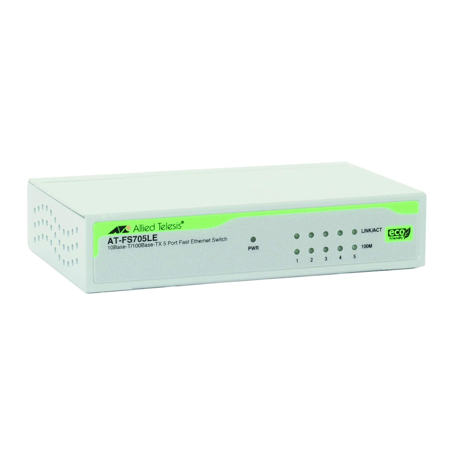
Chapter 1 Overview The AT-FS705LE Fast Ethernet Switch is a 10Base-T/100Base-TX unmanaged switch. The switch provides you with a simple, cost-effective solution for Ethernet switching between end- nodes operating at either 10 Mbps or 100 Mbps. Figure 1 and Figure 2 show the front and back panels of the switch. -
Page 14: Key Features
Overview Figure 2 AT-FS705LE Back Panel Key Features The AT-FS705LE switch has the following features: ❑ Non-blocking architecture ❑ Five Auto-Negotiating 10/100 Mbps twisted pair ports with RJ-45 connectors wired as MDI-X ❑ One Auto-Negotiating 10/100 Mbps uplink twisted pair port with RJ-45 connector wired as MDI. -
Page 15: Physical Description
(328 feet) using Category 5 cable. The ports are IEEE 802.3u Auto-Negotiation compliant. This means that the ports can automatically configure their speed and duplex mode to match the capabilities of the end-nodes connected to the ports. AT-FS705LE Installation Guide... -
Page 16: Port 5 And The Uplink Port
Overview Note In order for a twisted pair port on the AT-FS705LE switch to successfully Auto- Negotiate its duplex mode with an end- node, the end-node should also be using Auto-Negotiation. Otherwise, a duplex mode mismatch can occur. The twisted... -
Page 17: Status Leds
Refer to Table 1 for a description of the switch’s LEDs. LEDs Color Green 100M Green AT-FS705LE Installation Guide Table 1 LEDs Description Power is applied to the switch. The port is operating at 100 Mbps. The port is operating at 10... -
Page 18: Auto Mdi/Mdi-X
Overview Table 1 LEDs (continued) LEDs Color LINK/ACT Green Flashing Green Auto MDI/MDI-X An RJ-45 twisted pair port on a 10 Mbps or 100 Mbps Ethernet network device can have one of two possible wiring configurations: MDI or MDI-X, while the twisted pair port on a switch or hub is usually MDI-X. -
Page 19: Auto-Negotiation
AT-FS705LE Installation Guide The AT-FS705LE switch features auto MDI/ MDI/X on all ports. Auto MDI/MDI-X automatically determines the configuration of the port on the end-node to which it is connected and then configures itself appropriately. For example, if a port on a... - Page 20 Overview Each twisted pair port on the AT-FS705LE switch can operate in either half-duplex or full- duplex mode. Since these twisted pair ports are IEEE 802.3u-compliant, the duplex mode can be set automatically through Auto-Negotiation. With Auto-Negotiation, if the end-node is capable of full-duplex, the port is set automatically to full-duplex mode.
-
Page 21: Mac Address Table
AT-FS705LE Installation Guide MAC Address Table The heart of an Ethernet switch is the Media Access Control (MAC) address table. Every device that you attach to an Ethernet network has a MAC address. This address is assigned to the device by the device’s manufacturer. For... - Page 22 The MAC address table in the AT-FS705LE switch can store up to 2,000 MAC addresses. To prevent the table from becoming filled with...
-
Page 23: External Power Supply
External Power Supply The AT-FS705LE switch uses an external AC/ DC power adapter that comes standard with the switch. -
Page 24: Network Topologies
Overview Network Topologies The AT-FS705LE switch can be used in a variety of network topologies, such as standalone or back-to-back. Both topologies are described below. Standalone Topology Figure 3 illustrates a network of one AT- FS705LE switch used to interconnect four workstations and a server. -
Page 25: Back-To-Back Topology
AT-FS705LE Installation Guide Back-to-Back Topology Figure 4 illustrates a network of two AT-FS705LE switches that have been interconnected using one of the Uplink ports on one of the units. Using the Uplink port eliminates the need for a crossover cable to interconnect the switches. -
Page 27: Chapter 2 Installation
Make sure the following items are included in your package. If any item is missing or damaged, contact your Allied Telesyn sales representative for assistance. ❑ An AT-FS705LE Fast Ethernet Switch ❑ One external power adapter ❑ Four protective rubber feet (for desktop use only) ❑... -
Page 28: Selecting A Site
Installation Note For wall-mount installation, the screws, plastic anchors, and any other material necessary to physically mount the switch to the wall are not provided. Selecting a Site Be sure to observe the following requirements when choosing a site for your switch. ❑... -
Page 29: Reviewing Safety Guidelines
Power cord is used as a disconnection device. To de-energize equipment, disconnect the power cord. Caution Pluggable Equipment: The socket outlet should be installed near the equipment and should be easily accessible. AT-FS705LE Installation Guide Type of Cable Category 5 Category 5 Maximum Distance 100 m... - Page 30 Installation Caution Air vents: The air vents must not be blocked on the unit and must have free access to the room ambient air for cooling. Caution Operating Temperature: This product is designed for a maximum ambient temperature of 40°C. Caution All Countries: Install this product in accordance with local and National...
-
Page 31: Installing The Switch On A Table Or Desktop
Figure 1. Figure 1 Attaching the Rubber Feet 3. Place the switch on a flat and secure surface, leaving ample space around the switch for ventilation. 4. Connected the twisted pair cables to the twisted pair ports. AT-FS705LE Installation Guide... - Page 32 Installation Note You can use either Port 5 or the Uplink port, but you cannot use both simultaneously. When connecting a twisted pair cable to a port, observe the following guidelines: • An RJ-45 connector should fit snugly into the port on the switch. The tab on the con- nector should lock the connector into place.
- Page 33 7. Power ON the end-nodes connected to the switch. 8. Check that all the LINK/ACT LEDs are green. If any of the LEDs is OFF, refer to “Troubleshooting” on page 27 for instructions. The switch is now ready for use. AT-FS705LE Installation Guide...
-
Page 34: Wall-Mounting The Switch
Installation Wall-Mounting the Switch The switch can be mounted vertically or horizontally on a wall using the keyholes on the bottom of the switch. Except for the plastic anchors, the screws and other materials necessary to mount the switch on a wall are not provided. - Page 35 When connecting a twisted pair cable to a port, observe the following guidelines: • An RJ-45 connector should fit snugly into the port on the switch. The tab on the con- nector should lock the connector into place. AT-FS705LE Installation Guide...
- Page 36 Installation • You should check to be sure that you are using the appropriate type of twisted pair cabling. Refer to Table 4 on page 10 for twisted pair cable specifications. • Since the twisted pair port, when operating in Auto-Negotiation, is Auto MDI/MDI-X, you can use either a straight-through or crossover twisted pair cable to connect any type of network device to a port on the...
- Page 37 8. Power ON the end-nodes connected to the switch. 9. Check that all the LINK/ACT LEDs are green. If any of the LEDs is OFF, refer to “Troubleshooting” on page 27 for instructions. The switch is now ready for use. AT-FS705LE Installation Guide...
-
Page 38: Warranty Registration
Installation Warranty Registration When you have finished installing the product, register your product by completing the enclosed warranty card and sending it in. You can also fill out the registration online by selecting “Warranties” under “Support & Services” from www.alliedtelesyn.com. -
Page 39: Chapter 3 Troubleshooting
❑ Check to be sure that the power adapter is securely connected to the power source and to the DC connector on the front of the AT-FS705LE switch. ❑ Check to be sure that the power outlet has power by connecting another device to it. - Page 40 Troubleshooting If the LINK/ACT LED is OFF, do the following: ❑ Check to be sure that the end-node connected to the port on the switch is powered ON. If the end-node is OFF, power the unit ON. ❑ Check that the cable is securely connected to the port on the switch and on the end- node.
-
Page 41: Appendix A Technical Specifications
Appendix A Technical Specifications Physical Dimensions: Environmental Temperature Maximum Operating: Maximum Storage: Humidity Operating Humidity: Storage Humidity Altitude Operating and Storage: Up to 3,048 meters W x D x H 100 x 78.5 x 26 mm (3.93 x 3.09 x 1.02 in) 0°... -
Page 42: Electrical Rating
Technical Specifications Electrical Rating Input Supply Voltage: Power Current: Power Consumption: Standards & Compliance IEEE 802.3 IEEE 802.3u Electrical/Mechanical Approvals VCCI C-TICK 7.5V 1A Maximum 8W Maximum 10T Ethernet 100TX Fast Ethernet FCC Part 15 Class B UL60950 ( EN55022 Class B EN60950 (TUV) EN55024 VCCI Class B... -
Page 43: Pinout Assignments
RJ-45 connector. Figure 1 RJ-45 Pin Assignments Table 5 lists the 10Base-T/100Base-TX connector pins and their signals when the port is operating in either MDI or MDI-X configuration. Table 1: RJ-45 Pin Signals MDI-X Signal (Default) AT-FS705LE Installation Guide Signal... -
Page 45: Translated Safety And Emission Information
Appendix B Translated Safety and Emission Information Important: This appendix contains multiple- language translations for the safety statements in this guide. Wichtig: Dieser Anhang enthält Übersetzungen der in diesem Handbuch enthaltenen Sicherheitshinweise in mehreren Sprachen. Vigtigt: Dette tillæg indeholder oversættelser i flere sprog af sikkerhedsadvarslerne i denne håndbog. - Page 46 Translated Safety and Emission Information Viktig: Dette tillegget inneholder oversettelser til flere språk av sikkerhetsinformasjonen i denne veiledningen. Importante: Este anexo contém traduções em vários idiomas das advertências de segurança neste guia. Importante: Este apéndice contiene traducciones en múltiples idiomas de los mensajes de seguridad incluidos en esta guía.
- Page 47 Connect the equipment into an outlet on a circuit different from that to which the receiver is connected. Consult the dealer or an experienced radio/TV technician for help. AT-FS705LE Installation Guide Allied Telesyn, Inc. 960 Stewart Drive, Suite B Sunnyvale, CA 94085 USA...
- Page 48 Translated Safety and Emission Information Changes and modifications not expressly approved by the manufacturer or registrant of this equipment can void your authority to operate this equipment under Federal Communications Commission rules. This Class B digital apparatus meets all requirements of the Canadian Interference-Causing Equipment Regulations.
- Page 49 AT-FS705LE Installation Guide Europe - EU: Use TÜV licensed AC adapter of DC 7.5V, 1A. USA/Canada: Use a UL Listed/CSA Certified AC adapter of DC 7.5V, 1A.
- Page 50 Translated Safety and Emission Information Normen: Dieses Produkt erfüllt die Anforderungen der nachfolgenden Normen. Hochfrequenzstörung Warnung: Bei Verwendung zu Hause kann dieses Produkt Funkstörungen hervorrufen. In diesem Fall müßte der Anwender angemessene Gegenmaßnahmen ergreifen. Störsicherheit Elektrische Sicherheit Sicherheit Vorsicht: Das netzkabel dient zum trennen der stromversorgung.
- Page 51 Alle Lande: Installation af produktet skal ske i overensstemmelse med lokal og national lovgivning for elektriske installationer. Brug kun TÜV godkendt vekselstrømstransformator på 7.5 V jævnstrøm, AT-FS705LE Installation Guide FCC Klasse B EN55022 Klasse B VCCI Klasse B C-TICK EN55024...
- Page 52 Translated Safety and Emission Information Eisen: Dit product voldoet aan de volgende eisen. RFI Emissie Waarschuwing: Binnenshuis kan dit product radiostoring veroorzaken, in welk geval de gebruiker verplicht kan worden om gepaste maatregelen te nemen. Immuniteit Electrische Veiligheid Veiligheid Waarschuwing: Het toestel wordt uitgeschakeld door de stroomkabel te ontkoppelen.Om het toestel stroomloos te maken: de stroomkabel ontkoppelen.
- Page 53 Pour Tous Pays: Installer le matériel conformément aux normes électriques nationales et locales. Utiliser un adaptateur secteur conforme TÜV de 7,5 V, 1 A en courant continu. AT-FS705LE Installation Guide FCC Classe B EN55022 Classe B VCCI Classe B C-TICK...
- Page 54 Translated Safety and Emission Information Standardit: Tämä tuote on seuraavien standardien mukainen. Radioaaltojen häirintä Varoitus: Kotiolosuhteissa tämä laite voi aiheuttaa radioaaltojen häiröitä, missä tapauksessa laitteen käyttäjän on mahdollisesti ryhdyttävä tarpeellisiin toimenpiteisiin. Kestävyys Sähköturvallisuus Turvallisuus Huomautus: Virtajohtoa käytetään virrankatkaisulaitteena. Virta katkaistaan irrottamalla virtajohto.
- Page 55 Tutti I Paesi: installare il prodotto in conformità delle vigenti normative elettriche nazionali. Utilizzare l’adattatore per c.a. da 7,5 V c.c. e 1 A conforme alla normativa TÜV. AT-FS705LE Installation Guide FCC Classe B EN55022 Classe B VCCI Classe B...
- Page 56 Translated Safety and Emission Information Sikkerhetsnormer: Dette produktet tilfredsstiller følgende sikkerhetsnormer. RFI stråling Advarsel: Hvis dette produktet benyttes til privat bruk, kan produktet forårsake radioforstyrrelse. Hvis dette skjer, må brukeren ta de nødvendige forholdsregler. Immunitet Elektrisk sikkerhet Sikkerhet Forsiktig: Strømledningen brukes til å frakoble utstyret.
- Page 57 Use um adaptador de corrente alternada com saída DC de 7,5V e 1A em conformidade com as especificações da TÜV. AT-FS705LE Installation Guide FCC Classe B EN55022 Classe B VCCI Classe B C-TICK...
- Page 58 Translated Safety and Emission Information Estándares: Este producto cumple con los siguientes estándares. Emisión RFI Advertencia: en un entorno doméstico, este producto puede causar radiointerferencias, en cuyo caso, puede requerirse del usuario que tome las medidas que sean convenientes al respecto. Inmunidad Seguridad eléctrica Seguridad...
- Page 59 40 grader Celsius. Alla Länder: Installera produkten i enlighet med lokala och statliga bestämmelser för elektrisk utrustning. Använd en växelströmsanslutningsenhet licensierad av TÜV.Likström 7,5V, 1A. AT-FS705LE Installation Guide FCC Klass B EN55022 Klass B VCCI Klass B C-TICK EN55024 EN60950 (TUV)
Need help?
Do you have a question about the AT-FS705LE and is the answer not in the manual?
Questions and answers