Table of Contents
Advertisement
Installation Instructions
Model Numbers:
ZCV3622N, ZCV3622NE, ZCV3622LP, ZCV3622LPE
ZCVRB3622N, ZCVRB3622NE, ZCVRB3622LP, ZCVRB3622LPE,
Certified to:
ANSI Z21.88-2014 • CSA 2.33-2014
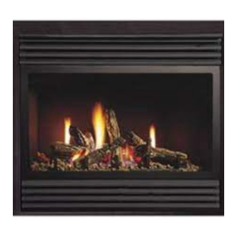
ZERO CLEARANCE VENTED GAS FIREPLACE HEATER
This appliance may be installed in an
aftermarket, permanently located,
manufactured home (USA only) or mobile
home, where not prohibited by local codes.
This appliance is only for use with the type
of gas indicated on the rating plate. This
appliance is not convertible for use with
other gases, unless a certified kit is used.
INSTALLER: Leave this manual with the appliance.
CONSUMER: Retain this manual for future reference.
For Propane Horizontal installations the
venting must be an additional one foot
above the minimum vertical rise off the flue
before going horizontal.
ZCV3622 SOLARA
ZCVRB3622 SKYLINE
A Division of R-Co. Inc.
2340 Logan Ave.
Winnipeg, Manitoba Canada
R2R 2V3 Ph.: (204) 632-1962
Printed in Canada March 8, 2016
Part# 36ZCV-MAN-14
Advertisement
Table of Contents

Related Manuals for Kingsman ZCV3622N


Summary of Contents for Kingsman ZCV3622N
-
Page 1: Installation Instructions
Installation Instructions Model Numbers: ZCV3622N, ZCV3622NE, ZCV3622LP, ZCV3622LPE ZCV3622 SOLARA ZCVRB3622N, ZCVRB3622NE, ZCVRB3622LP, ZCVRB3622LPE, Certified to: ZCVRB3622 SKYLINE ANSI Z21.88-2014 • CSA 2.33-2014 ZERO CLEARANCE VENTED GAS FIREPLACE HEATER This appliance may be installed in an aftermarket, permanently located, manufactured home (USA only) or mobile home, where not prohibited by local codes. -
Page 2: Table Of Contents
Table of Contents INFORMATION Table of Contents……………………………………………………………..............Glass Safety / Termination Cap Safety- All Units……………………………………………………………………….. Pre-installation Questions and Answers…………………………………..............Operating Instructions………………………………………………………..............Safety Screen Installation…………………………………………………………………………………………………. Warnings, Installations, and Operations…………………………………..............Recommendations for Finishing of Clean View Installations.................. Mobile Home/Manufactured Housing Installation……………………............... Nailing Tab Guide..............................ZCV3622 / ZCVRB3622 Framing Your Gas Fireplace…………………………………………………………………. - Page 3 VENTING Vent Termination……………………………………………………………………………………………………………. General Vent Installation…………………………………………………………………………………………………... Installation of Side Wall Venting…………………………………………………………………………………………... Venting Routes And Components………………………………………………………………………………………… Horizontal Venting Table…………………………………………………………………………………………………... Venting Straight Up Through Roof………………………………………………………………………………………... 59-60 Vertical Venting over 15 Feet……………………………………………………………………………………………… Z47ST24 / Z47ST36 Horizontal Snorkel Terminations…………………………………………………………………. Approved for Power Vent PVH58…………………………………………………………………………………………. PARTS LISTS PVH58 Parts List…………………………………………………………………………………………………………….
-
Page 4: Glass Safety / Termination Cap Safety- All Units
-Glass Safety- All Units IT IS THE RESPONSIBILITY OF THE HOME OWNER TO ENSURE THAT NO ONE TOUCHES A HOT APPLIANCE. If the barrier becomes damaged, the barrier shall be replaced with the manufacturer’s barrier for this appliance. Any safety screen, guard, or barrier removed for servicing the appliance, must be replaced prior to operating the appliance. -
Page 5: Pre-Installation Questions And Answers
Pre-installation Questions and Answers About curing of the paint Your stove or fireplace has been painted with the highest quality silicone stove paint. This paint dries quickly in 15-20 minutes when first applied at the factory. However, due to the high temperature silicone components, the paint will cure when heat is applied to the appliance as it is first used. -
Page 6: Safety Screen Installation
Safety Screen Installation Z-SERIES CSS Contents of Kit: [1] Safety Screen (2 for MDV31) [2] Top and Bottom Angles (4 for MDV31) [10] DT Screws (Depending on screen size) NOTE: Screens are symmetrical from top to bottom. ⚠ WARNING: Wait until unit is COMPLETELY cool before touching glass or attempting to install or remove Child Safety Screens. -
Page 7: Warnings, Installations And Operations
Warnings, Installations and Operations Installation Regulations This gas appliance must be installed by a qualified installer in accordance with local building codes, or in the absence of local codes, with the current CAN/CSA-B149.1 or .2 Installation Code (in Canada) or the current National Fuel Gas Code Z223.1- NFPA 54 when installed in the United States. This appliance, when installed, must be electrically connected and grounded in accordance with local codes, or in the absence of local codes, with the current CSA C22.1 Canadian Electrical Code or with the National Electrical Code;... -
Page 8: Operations And Maintenance Instructions
Gas fired appliances may be used only for supplemental heat and/or decorative purposes and under no circumstances shall they provide a primary heat source. This appliance must not be connected to a chimney flue serving a separate solid-fuel burning appliance. NOTE: It is recommended that a Carbon Monoxide (CO) Detector be installed in or near bedrooms and on all levels of your home. -
Page 9: Recommendations For Finishing Of Clean View Installations
Recommendations for Finishing of Clean View Linear Products When finishing the wall around the fireplace, it is critical that the wall covering be fastened properly. It is acceptable to pre-drill holes and use self-tapping screws which may be used to fasten a backer for tile, marble, etc. Screws being installed through non-combustible board should be self-tapping type with a maximum length of 2 inches. -
Page 10: Mobile Home/Manufactured Housing Installation
Mobile Home/Manufactured Housing Installation This Direct Vent System Appliance must be installed in accordance with the manufacturer’s installation instructions and the Manufactured Home Construction and Safety Standard Title 24 CFR, Part 3280, or the current Standard for Fire Safety Criteria for Manufactured Home Installations, Sites, and Communities ANSI/NFPA 501A, and with CAN/CSA Z240 MH Mobile Home Standard in Canada. -
Page 11: Nailing Tab Guide
ZCV3622 / ZCVRB3622 Nailing Tab Guide 2 Nailing Tabs are located on each side of the fireplace front frame. ZCV3622 ZCVRB3622 These Nailing Tabs can be used in two ways: 1/2” Drywall Flush with Face of Fireplace –Fireplace and -Fireplace to be Framing Flush with Face of Fireplace Combustible Wall to be covered with a surround and / or Non- covered with Non-Combustibles (e.g. -
Page 12: Zcv3622 / Zcvrb3622 Framing Your Gas Fireplace
ZCV3622 / ZCVRB3622 Framing Your Gas Fireplace This section is intended for qualified installers only. Before beginning, make note of where the gas and electrical accesses are located on the unit. This will streamline the construction process. Furthermore, familiarize yourself with the venting and clearance requirements (see Venting section) for this appliance. -
Page 13: Locating Your Appliance / Fireplace Dimensions
ZCV3622 / ZCVRB3622 - Locating your Appliance Installing with Top Vent A - Flat on a wall D - As a room divider B - Across the corner E - Flat on wall corner C - As an island F - Exterior wall Island installation with a top vent is possible as long as the horizontal portion of the vent system does not exceed 20 feet (6.1 m). -
Page 14: Zcv3622 / Zcvrb3622 Installation
ZCV3622 / ZCVRB3622 Framing Dimensions Determine whether face of fireplace will be: Flush with finished wall (e.g., for surround, cultured stone or other non combustible covering). Flush with framing (to be covered with concrete board for a Flat Wall appearance). Refer to Nailing Tab Guide section also. -
Page 15: Facing Requirements
ZCV3622 / ZCVRB3622 Facing Requirements Required Non-Combustible Areas- If you are covering the face of the fireplace: Combustibles (i.e. Drywall) may be installed up to edge of fireplace only. NOTE: MATERIALS COVERING THE FACE OF THE FIREPLACE MUST BE NON-COMBUSTIBLE It is also recommended (but optional) to attach Non-combustible facing to framing. -
Page 16: Clearance To Combustibles
ZCV3622 / ZCVRB3622 Clearance to Combustibles Clearance to Combustibles ZCV3622 / ZCVRB3622 36” [92cm] Front 0” [0cm] Back (from Stand-offs) 0” [0cm] Side (from Stand-offs) 0” [0cm] Floor* Minimum Ceiling Height (from bottom of fireplace) 46-1/2” *Clearance to Top of 90° bend can be reduced by 1”... -
Page 17: Zcv3622 / Zcvrb3622 Mantel Clearances
ZCV3622 / ZCV3622RB Mantel Clearances Before installing any mantels it is important to determine the combustibility of its material(s). There are two types of mantels to consider: Combustible and Non-Combustible. A Combustible Mantel is one that consists of material(s) that may discolor, combust, or lose its integrity in the presence of heat. -
Page 18: Gas Line Installation
1/2 PSIG (3.5 KPa). NOTE: The gas line connection may be made of 1/2” rigid pipe or an Approved Kingsman Flex Connector, such as FP15GC. -
Page 19: Millivolt System, Lighting, And Burner Control
Millivolt System, Lighting, and Burner Control FOR YOUR SAFETY READ BEFORE LIGHTING WARNING: If you do not follow these instructions exactly, a fire or explosion may result causing property damage, personal injury or loss of life. BEFORE LIGHTING Immediately call your gas supplier from a neighbour’s phone. Follow the This appliance has a pilot which must be lighted by hand. -
Page 20: Burner System Maintenance
Burner System Maintenance It is recommended to annually inspect and clean the Burner System to prevent malfunction and / or sooting. This operation should be performed by your dealer or a qualified technician. ⚠ -CAUTION- Before servicing the burner system ensure that the gas supply is turned OFF and disconnect all electrical connections to the appliance. -
Page 21: Conversion Kit Instructions - Part A
Conversion Kit Instructions – PART A ⚠ Caution : The gas supply shall be shut off prior to disconnecting the electrical power, before proceeding with the conversion. IMPORTANT: Always check for gas leaks with a soap and water solution. DO NOT USE OPEN FLAME FOR LEAK TESTING. ⚠... - Page 22 ZCVRB3622 Burner System Removal Burner Burner Retainer Retainer Plumbing Access Remove four [4] screws holding down the false bottom. Remove the four [4] screws holding down the burner tube assembly. Slide the burner tube towards the left to remove from orifice. Remove main orifice using a 1/2”...
-
Page 23: Conversion Kit Instructions – Part A
Conversion Kit Instructions – PART A Burner Orifice Kit Number Description Pilot Orifice Brass Nipple Air Shutter Hi/Lo Regulator Brass (1000-255) LP Conversion 1001-P167SI 1001-P202SI 3/8” 3622-CKLP 1000-P201VE -Millivolt- #30 (977.167) (0.907.202) NG Conversion 1001-P165SI 1001-P201SI 3622-CKNG 1000-P201VE 3/16” #51 (977.165) -Millivolt- (0.907.201) LP Conversion... -
Page 24: Gas Conversion Kit For Top Convertible Pilot Part B -Millivolt
Gas Conversion for Top Convertible Pilot (Series 019065X) – PART B Instructions for converting SIT 190 series pilot burner injection from NG to LPG and from LPG to NG only. This information should be considered as supplemental to the Appliance Manufacturer’s Instructions. WARNING: The installation of this conversion kit must only be undertaken by a qualified and certified gas appliance installer. -
Page 25: Gas Conversion Kit For Top Convertible Pilot Part B -Ipi
Gas Conversion for Top Convertible Pilot – Part B (series 0190XYZ) Instructions for converting SIT 190 series pilot burner injector from NG to LPG and from LPG to NG only. This information should be considered as supplemental to the Appliance Manufacturer's Instructions. WARNING! The installation of this conversion kit must only be undertaken by a qualified and certified gas appliance installer. -
Page 26: Gas Conversion For Modulator - Part C
Gas Conversion for Modulator – PART C... -
Page 27: Ipi Electronic Ignition System
IPI Electronic Ignition System Overview The IPI system is an advanced burner controller that provides you with the option of having either a Standing-Pilot, or an intermittent igniting system. This alternating mode is controlled by the CPI/IPI Switch (Continuous Pilot Ignition/Intermittent Pilot Ignition) located on the IPI System Box. -
Page 28: Remote Control Operation
-Remote Control Operation- The Proflame GTM is configured to control the on/off main burner operation, its flame levels, and provides on/off and Smart thermostatic control of the appliance. Transmitter Remote Receiver Transmitter Room Thermostat ( Transmitter Operation) The Transmitter is powered by 3 AAA type batteries. A Mode The Remote Control can operate as a room thermostat. -
Page 29: Ipi Electronic Ignition Parts List - Standard System
IPI Electronic Ignition Parts List – Standard System ITEM NO. PART NO. DESCRIPTION 1006-P002si Valve IPI Hi/Lo NG 1006-P003si Valve IPI Hi/Lo LP 1002-P047si Pilot Assembly-LP 1002-P033si Pilot Assembly-NG 1002-P017si Spark Electrode (with wire) *1002-P119si Spark Electrode (with wire- 35” Length) 1002-P903si Electrode Flame Sensor *1002-P910si... -
Page 30: Configuration 1: Basic Manual Hi / Lo And Manual Off
Configuration #1: Basic manual HI/LO and manual ON/OFF capabilities. -
Page 31: Configuration 2: Remote On / Off And Manual Hi / Lo
Receiver Module .584.523/521/221 1001-P221SI Receiver Module .584.523/521/221 1001-P221SI... -
Page 32: Operating The Receiver Without Batteries For Gt / Egt / Gtm / Egtm Remote Controls
EGTM / GTM System -No Batteries -Wiring Harness P/N 1002-P906si required. -Millivolt Systems will also require Power Adapter P/N 1002-P850si. The Remote Receiver & IPI or Millivolt system can be powered by the AC Adapter. This is advantageous if you do not want to use batteries. -
Page 33: Electronic Ignition Lighting Instructions
Electronic Ignition Lighting Instructions If you do not follow these instructions exactly, a fire or explosion may result causing property damage, personal injury or loss of life. Always light the pilot whether for the first time or if the gas supply has ran out with the glass door opened or removed. FOR YOUR SAFETY READ BEFORE LIGHTING: A. -
Page 34: Proflame 2 Parts List
Proflame 2 Parts List ITEM NO. PART NO. DESCRIPTION 1006-P040si Hand Held Transmitter with LCD display (GTMFSLA - Black) 0.584.040 1006-P042si Hand Held Transmitter with LCD display (GTMFL - Black) 0.584.042 1006-P305si Integrated Fireplace Control (Complete Power Vent Ready) 0.584.305 1006-P306si Integrated Fireplace Control (Complete No Power Vent) 0.584.306 1006-P307si... -
Page 36: Proflame 2 Module
Proflame 2 Module INTRODUCTION The Proflame2 IFC (Integrated Fireplace Control) board is a device that allows the automatic ignition and pilot flame supervision, to command the functions of a hearth appliance. It is configured to control the ON/OFF main burner operation, giving the choice of both IPI (intermittent pilot ignition), and CPI (continuous pilot ignition) modes. -
Page 37: Proflame 2 Remote Control
Proflame 2 Remote Control Battery Holder LCD Display ON / OFF Key Thermostat Key UP / DOWN Arrow Key Mode Key Follow the procedure below. • Install the 4 AA batteries into the battery holder (if present). Install the 3 AAA type batteries in the battery bay, located on the base of the Remote Control. -
Page 38: Door And Glass Information
ZCV3322 / ZCVRB3622 Door and Glass Information Glass Cleaning Spring Replacement- ZCV3622, ZCVRB3622 It will be necessary to clean the glass periodically. *Over time, spring may need to be replaced if tension is During start- up, condensation, which is normal, forms lost. -
Page 39: Zcv3622 / Zcvrb3622 Uhs Box / Component Locations
(See Each Section For Connections & Wiring) NOTE: The gas line connection may be made of Power 1/2” rigid pipe or an Junction Vent Approved Kingsman Flex Control Connector, such as FP15GC. Since some Module municipalities have additional local codes, it is... -
Page 40: Zcv3622 / Zcvrb3622 Z36Fk Fan Kit Installation
ZCV3622 / ZCVRB3622 Z36FK Fan Kit Installation ⚠ WARNING Z36FK Parts List: [1] Fan c/w 4 ft. cord & 2-14” leads Electrical Grounding Instructions [1] Wall Mount Variable speed This appliance is equipped with a three prong (grounding) plug for your protection against control shock hazard and should be plugged directly into a properly grounded three-prong [1] Thermodisc... -
Page 41: Fan Speed Control Outside Of Fireplace
Fan Speed Control Outside of Fireplace If you plan to locate the variable speed control switch for the fan outside of the fireplace and you require a constant source of AC power inside the unit for another accessory such as lights or an IPI valve system, follow one of the procedures below. -
Page 42: Zcv3622 / Zcvrb3622 Liner Installation Guide
ZCV3622 / ZCVRB3622 ML / PRL Liner Installation Guide Make note of the position of the air adjustment plate before removing it. This position will have to be recalled when the air adjustment plate is reinstalled. Remove three [3] mounting screws from air adjustment plate and extract it from the firebox. (NOTE: The false bottom will have to be removed on model ZCVRB3622.) Remove the [1] Liner Retaining Screw from each side of the firebox. -
Page 43: Ulk2 Universal Light Kit
ULK2 Universal Light Kit ( Optional Accent Lighting Kit) ZCV3622, ZCVRB3622 Please follow the current ANSI/NFPA 70 National Electrical Code in the USA and CAN/CSA C22.1 Canadian National Electrical Code in Canada. Contents of Kit: [2] 12V Halogen Lamps ... - Page 44 ZCVRB3622 ZCV3622 STEP 3: Place Lamps in position in firebox. Attach to fireplace with a single screw at the locations shown above for each unit. Lamps can be placed facing upward or sideways. Replace burner tube and false bottom, along with pilot shield.
-
Page 45: Logc51 -5 Piece Oak Log Set For Zcv3622
LOGC51 5 Piece Oak Log Set for ZCV3622 Glowing Embers Lava Rock LOG 1 LOG 5 LOG 2 LOG 3 LOG 4 LOG 1 LOG 3 LOG 2 LOG 5 LOG 5 LOG 4 Lava Rock Glowing Embers Lava Rock... -
Page 46: Mqlogc22
MQLOGC22 for MQZDV3318 / 3622 / ZCV3622 WARNING: Failure to position the parts in accordance with these diagrams or failure to use only parts specifically approved with this appliance may result in property damage or personal injury. NOTE: Log 1 is a two piece assembly. Log 1 assembled and ready for install. -
Page 47: Mqlogc22
MQLOGC22 for MQZDV3318 / 3622 / ZCV3622 STEP 3: Align the hole on the bottom of log #3 with the log STEP 4: Place Log #4 into place as shown. Do Not place #3 placement tab and the rest log #3 on log #2 as shown. directly over top of the multiple porting area on the left side. -
Page 48: Mqlogc23 -4 Piece Driftwood Log Set For Zcv3622
MQLOGC23 4 Piece Driftwood Log Set for ZCV3622 Glowing Embers Lava Rock LOG 1 LOG 2 LOG 4 LOG 3 LOG 1 LOG 2 LOG 3 LOG 4 Glowing Embers Lava Rock Lava Rock... -
Page 49: Mqrsp5
MQRSP5 for MQZDV3318/3622/ZCV3622 Step 1: Remove the grate bar by removing the 2 Screws MQRSP5 Parts List located on the left and right side of the grate bar as illustrated. Remove the 2 ember plates once the grate bar is removed. The 1 each MQRSP5 Rock Platform 2 screws removed must be re-installed once the grate bar is 1 each Lava Rock... - Page 50 MQRSP5 for MQZDV3318/3622/ZCV3622 Step 6: Place rocks #6 into place as shown. Do not place Step 7: Place rocks #4 into position as shown. Place the highlighted rocks into position being sure that they are crossing directly over the multiple porting areas. over the single line porting.
-
Page 51: Mq Accessories Available - Zcvrb3622
Accessories for Skyline, ZCVRB3622, & ZRB46 Ribbon Burner Units ACCESSORY ITEM MQRB3632 MQRB4236 ZCVRB3622 White Glass MQG5W Yes / 5LB MAX 5LB Bag c/w Unit MQ Dealer Only Bronze Glass Yes / 5LB MAX Yes / 5LB MAX 5LB Bag c/w MQG5C Unit Cobalt Blue Glass... - Page 52 ⚠ NOTE: Glass Media must be evenly spread over the Burner and False Bottom as described on last page before Rock / Stones / and Log Accessories are placed. MQROCK2, MQROCK3, MQRBD1 - Place rocks randomly onto False Bottom. Be careful not to cover any part of the Burner Tube as sooting may occur.
-
Page 53: Zcv36S1 Surround Installation
ZCV36S1BL ZCV3622 Surround Installation Parts List: [1] Surround, [2] #6 DT Black Screws Step 1: Slide Surround over fireplace Step 2: frame. Install DT screws into top corners. Step 3: Open Lower Panel and Install DT Screws through Surround into fireplace frame. -
Page 54: Zcv3622Rbs Surround Installation
ZCVRB36S Surround Installation Side Fillers Each kit contains: Surround Size: (Left and Right) (36”W x 22-7/8”) (Qty-1) Surround Frame (Qty-2) Surround Side Fillers ZCVRB36SBL (Qty-1) Surround Access Cover ZCVRB36SSS Surround Frame (Qty-6) #6 Self Tapping Screws NOTE: See Framing Flush With Face of Fireplace on Nailing Tab Guide Page. -
Page 55: Troubleshooting The Gas Control System
Troubleshooting the Gas Control System WARNING BEFORE DOING ANY GAS CONTROL SERVICE WORK, REMOVE THE GLASS FRONT. Before troubleshooting the gas control system, be sure external gas shut off is in the "On" position. Problem Possible Causes Corrective Action Spark igniter will not light. Defective or misaligned Check for spark at electrode and pilot: if no spark and electrode wire is electrode at pilot. -
Page 56: Vent Termination
Vent Termination WARNING: WHEN THE HORIZONTAL VENT TERMINATION IS ACCESSIBLE A CERTIFIED GUARD (SAFETY CAGE) SHALL Notes: BE INSTALLED. 1) Clearances are to the edge of the terminal plate. Add 6-3/4” to clearances to arrive at centerline. 2) Local codes or regulations may require different clearances. -
Page 57: General Vent Installation
General Vent Installation Information This gas appliance is approved to be vented either through the side wall or vertically through the roof. Only Kingsman Flex (Z-Flex) Venting Kits and components specifically approved and LABELED for this stove may be used. This appliance is also approved for use with Simpson-Duravent Direct Vent system (Model DV-GS Series), Ameri-Vent Direct Vent Pipe System, ICC Excel Direct, Metal Fab Sure-Seal DV and Selkirk Direct Temp. -
Page 58: Venting Routes And Components
ZCV3622 / ZCVRB3622 Venting Routes And Components Venting Routes and Components Since it is very important that the vent system maintain its How to Use the Horizontal Vent Table balance between the combustion air intake and the flue gas 1. Determine the height of the system and the number of exhaust, certain limitations as to vent configurations apply and bends required. -
Page 59: Venting Straight Up Through Roof
ZCV3622 / ZCVRB3622 Venting Straight Up Through Roof An Attic Insulation Shield must be installed where the vent passes from a lower living space into an attic space where the chimney is not enclosed. It is designed to keep insulation materials away from the chimney. When installing the Attic Insulation Shield where the chimney passes from a living space to an attic space, install the shield from below and nail in place using 1"... - Page 60 -Restrictor- Remove for Runs Under 15 Feet Clearances in horizontal venting. FDVVT40 43ft Straight-through roof support configuration; b) Flex bend configuration; c) Termination mounting...
-
Page 61: Vertical Venting Over 15 Feet
Vertical Venting over 15 Feet The Air Intake plate must be adjusted down to the lowest position when venting over 15 ft. vertical. 15ʼ OR OVER VERTICAL VENTING AIR INTAKE ADJUSTMENT PLATE NOTE: Unit comes preset for short horizontal or vertical venting under a 15 feet run. Follow these instructions when venting exceeds 15 foot run. -
Page 62: Z47St24 / Z47St36 Horizontal Snorkel Terminations
Z47ST24 / Z47ST36 Horizontal Snorkel Terminations Two snorkel terminations are available if a vertical rise is necessary on the exterior side of a building: Z47ST24 (24” Tall, 14-1/2” Center to Center) Z47ST36 (36” Tall, 26-1/2” Center to Center) Follow standard horizontal venting installation procedures. If the Snorkel Termination is to be located below grade, a window well is recommended with adequate and proper drainage as per local codes. -
Page 63: Approved For Power Vent Pvh58
Approved for Power Vent PVH58 The PVH58 Horizontal Power Vent is approved for the following models only: MDV31, MDV39, MQRB3632, ZDV3622, MQZDV3622, ZDVRB3622, HBZDV3624, HBZDV3628, HBZDV3632, MQHBZDV3636, HBZDV4224, HBZDV4228, HBZDV4232, MQHBZDV4236, HBZDV4740, MQHBZDV4736, MQRB4436, MQRB5143, MQRB6961, ZRB46, ZCV3622, ZCVRB3622, ZCV39, ZCV42, MCVP42, MCVST42, MQZDV3927*, MQZDV4634* *NOTE: For MQZDV3927 and MQZDV4634, Power Vent Control Module (PVCM) must be placed outside of Fireplace. -
Page 64: Pvh58 Parts List
PVH58 POWER VENT PARTS LIST NUMBER DESCRIPTION PVH58 Horizontal Power Vent Termination Power Vent Control Module – Millivolt Box PVC58MV Power Vent Control Module – IPI Box PVC58IPI Main Wiring Harness Assembly – Extension Harness (20ft) PVH20H 4/7 VENTING AND VENTING ADAPTERS For fireplaces to be converted to hard pipe (Duravent-DirectVent Pro, etc.) at the fireplace: Duravent Fireplace Adapter (ZRB46 Only) ZDVDKA... -
Page 65: Zcv3622 Parts List
Replacement Burner Assembly ZCV3622N (Millivolt) Fireplace Heater Rated, NG, 3622MQ-BNGSI Burner Assembly - Natural Gas c/w Valve 18,000BTU, Tempered Glass, Safety System (ZCV3622N) Screen 3622MQ-BLPSI Burner Assembly - Liquid Propane c/w Valve ZCV3622 NE (IPI) Fireplace Heater Rated, NG, System (ZCV3622LP) -
Page 66: Zcvrb3622 Parts List
ZCVRB3622 Parts List FIREPLACE PART NUMBERS Door Glass ZCVRB3622N (Millivolt) Linear Fireplace, Heater Rated, NG, 17,500BTU, Low-E Tempered Glass, 3600-311E Low-E Tempered Glass - ZCVRB3622 Safety Screen, 5lb Decorative Bronze Glass 36HB-123A Door Latch Assembly ZCVRB3622NE (IPI) Linear Fireplace, Heater Rated, NG, 17,500BTU, Low-E Tempered Glass, Safety 36HB-123 Upper Door Spring... -
Page 67: Zcv3622 / Zcvrb3622 Common Parts And Venting
ZCV3622 / ZCVRB3622 Common Parts and Venting Catalog 1000-085 Control Variable Speed KBWC-13BV Number Description Valve System Parts - New Top convertible SIT (Millivolt) Kingsman Fireplace Venting FP15GC Stainless Steel Gas Connector Number Description 1000-P136WR Generator/Thermopile ZDVHSK Horizontal Vent Starter Kit - 3 FT Length 1001-P069SI Electrode Sparker 915.069 TC SIT... -
Page 68: Limited Lifetime Warranty
During the first year after installation, we will provide a replacement for any component part of your unit found to be defective in materials or workmanship, including labour costs. Repair work requires prior approval by Kingsman, labour costs are based on a predetermined rate schedule and any repair work must be done through an authorized Kingsman dealer.
Need help?
Do you have a question about the ZCV3622N and is the answer not in the manual?
Questions and answers