Table of Contents
Advertisement
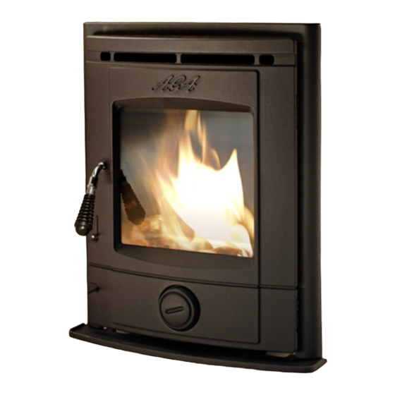
Stretton Insert Stove
This appliance is hot while in operation and retains its heat for a long period of time after use.
Children, aged or infirm persons should be supervised at all times and should not be allowed
to touch the hot working surfaces while in use or until the appliance has thoroughly cooled.
When using the stove in situations where children, aged and/or infirm persons are
present a fireguard must be used to prevent accidental contact with the stove. The fireguard
should be manufactured in accordance with BS 6539.
INSTALLATION AND OPERATING INSTRUCTIONS
Advertisement
Table of Contents

Related Manuals for AGA Stretton


Summary of Contents for AGA Stretton
- Page 1 Stretton Insert Stove This appliance is hot while in operation and retains its heat for a long period of time after use. Children, aged or infirm persons should be supervised at all times and should not be allowed to touch the hot working surfaces while in use or until the appliance has thoroughly cooled.
-
Page 2: Table Of Contents
TABLE OF CONTENTS PAGE NO. Insert Stove Installation & Operating Instructions ......General . -
Page 3: Insert Stove Installation & Operating Instructions
INSERT STOVE INSTALLATION & OPERATING INSTRUCTIONS NOTE: Please note that it is a legal requirement PRE-INSTALLATION under England & Wales Building Regulations that After removing the stove from the packaging, open the installation of the stove is either carried out the fire door and remove the loose packing. -
Page 4: Co Alarms
ALL FLUE INSTALLATIONS ARE THE Fig 2 RESPONSIBILITY OF THE INSTALLER Any existing chimney must be clear of obstruction and have been swept clean immediately before installation of the stove. If the stove is fitted in place of an open fire then the chimney should be swept one month after installation to clear any soot falls which may have occurred due to the difference in combustion between the stove and the open fire. - Page 5 Fig 5 Fig 4 Step 8 Then using the M6 screws secure the stove to the convection chamber. Push the insert stove against the fireplace before fully tightening these bolts. Step 4 Step 9 Drop the flexi flue liner down through the chimney, Push the rigid pipe back up through the flue outlet connect the 5 - 6”...
- Page 6 Fig.6 4. Cast Iron Side Liners 1. Grate Support 3. Optional Ashlip 2. Grate To insert the side liner bring the casting carefully towards the opening, the bottom edge needs to go towards the side it will fit to and the top edge goes to the centre of the stove.
-
Page 7: Down Draughts
9. Fire Fence When calculating combustion air requirements for this appliance use the following equation: 550mm Lay the fire fence into the slots provided ensuring per each kW of rated output above 5 kW should be that they slope from front to back so that no embers provided, where a flue draught stabiliser is used the can fall out through the fire fence. -
Page 8: Commissioning & Handover
Fig.10 COMMISSIONING & HANDOVER On completion of the installation allow a suitable period of time for any fire cement and mortar to dry out, when a small fire may be lit and checked to ensure the smoke and fumes are taken from the stove up the chimney and emitted safely to the atmosphere. -
Page 9: Stove Dimensions
Fig.12 STOVE DIMENSIONS Fig.13 TECHNICAL DATA Nominal Output Manufactured Smokeless Fuel Room 4.9kW Typical refuelling intervals to obtain nominal outputs 2 hours Flue Gas Mass Flow 3.3 g/s Flue Gas temp at nominal output Gross Weight: 100 kgs Flue Outlet 125 mm Log size 310 mm... -
Page 10: Primary Air Control Spin Valve
PRIMARY AIR CONTROL SPIN VALVE Fig.15 When burning manufactured smokeless fuels, the spin valve located near the bottom of the door, con- trols the primary air supply to the stove. For maxi- mum heat output and burn rate rotate the spin valve fully in an anti-clockwise direction. -
Page 11: Slow Burning
Fig.16 Fig.17 MAINTENANCE SLOW BURNING CREOSOTE - Formation and Need for Removal To achieve slow burning when burning wood close When some fuels are burned slowly, they produce the secondary air slide and open a few millimetres tar and other organic vapours, which combine with using the tool provided. -
Page 12: Important Notes
For your own safety by a competent service engineer. Use only these must be kept clean at all times. replacement parts recommended by AGA. Using unauthorised parts will invalidate your guarantee and may cause damage or IMPORTANT NOTES injury. -
Page 13: Lighting
4. A plan to deal with a chimney fire as follows: LIGHTING Notify the fire department. Before lighting the stove check with the installer Prepare occupants for immediate evacua- that the installation work and commissioning tion. checks described in the installation instructions Close all openings into the stove. - Page 14 NOTES...
- Page 15 NOTES...
-
Page 16: Exploded View
STRETTON INSERT STOVE EXPLODED VIEW FIRE DOOR - B00605AXX 19. LH BACK BRICK - H00203AXX FRONT - B00606AXX 20. SIDE BRICK - H00207AXX ASHLIP - B00607AXX 21. RH BACK BRICK - H00208AXX SPIN VALVE - B00608AXX 22. MIN SPRING HANDLE - L00539AXX WINDOW CLIP - CA1101 23.
Need help?
Do you have a question about the Stretton and is the answer not in the manual?
Questions and answers