Table of Contents
Advertisement
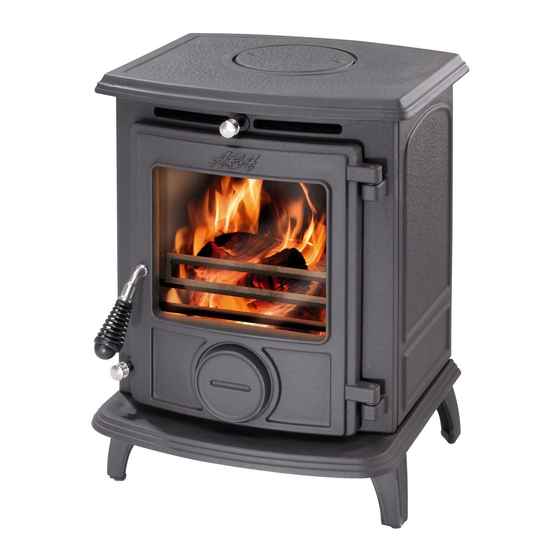
LITTLE WENLOCK
GAS STOVE
This appliance is hot while in operation and retains its heat for a long period of time after use.
Children,
aged or infirm persons should be supervised at all times and should not be allowed to touch the hot work-
ing surfaces while in use or until the appliance has thoroughly cooled.
INSTALLATION AND OPERATION INSTRUCTIONS
T o ensure safety, satisfaction and reliable service this stove should be installed by a suitably qualified
and competent person.
Advertisement
Table of Contents

Related Manuals for AGA LITTLE WENLOCK


Summary of Contents for AGA LITTLE WENLOCK
- Page 1 LITTLE WENLOCK GAS STOVE This appliance is hot while in operation and retains its heat for a long period of time after use. Children, aged or infirm persons should be supervised at all times and should not be allowed to touch the hot work- ing surfaces while in use or until the appliance has thoroughly cooled.
-
Page 2: Table Of Contents
TABLE OF CONTENTS PAGE NO. Operation Instructions ........... 2 Precautions . -
Page 3: Operation Instructions
OPERATION INSTRUCTIONS Fig. 1 WARNING: Do not operate the stove with the appliance door open, or if the glass panel in the front door has been broken or removed. Ensure that the door latch is fully locked. Keep the door spin valve closed at all times when stove is in operation. -
Page 4: What To Do If You Smell Gas
If stove fails to light repeat the above procedures. If stove fails to light after three attempts contact your local Aga Dealer. NOTE: During the first light-up period an odour will arise from the stove, this is due to the materi- als in the stove drying and curing. -
Page 5: Technical Data
Gas Type: result in property damage or injury. N.G .: I2H, G20, 20 mbar/8” wg (I.E. & G .B.) I2E, G20, 20 mbar/8” wg & Thank you for buying a Little Wenlock Gas Stove. room heater flue system should Manifold Pressure Maximum Setting inspected before use and at least annually. -
Page 6: Pre-Installation Assembly
Position stove in its chosen location and connect to the chimney/flue system. LOCATION There are many conditions to be considered when selecting the location for you Little wenlock Gas Stove. MINIMUM CLEARANCES TO COMBUSTIBLE MATERIALS (see Figs 11, 12, 13, 14) -
Page 7: Hearth Fitting
Fig.14 Fig.11 Fig.12 Fig.15 When installing the stove against a combustible wall leave a 6” space between the back of the stove and When installing the stove against a the wall for air circulation. non-combustible wall leave a 2” space (See Fig.12) between the back of the stove and the wall for air circulation. -
Page 8: Dimensions
Fig.16 Fig.17 The chimney and flue pipes intended for use with this appliance should mechanically robust, resistant to internal and external corrosion, non- combustible, and durable under the conditions to which they are likely to be subjected. The instal- lation flues appliances should... -
Page 9: Use Of Existing Chimneys And Flues
USE OF EXISTING CHIMNEYS AND FLUES Fig.19 (See Figs. 18, 19 & 20) An existing flue pipe or chimney that has proved to be satisfactory when used for solid fuel can nor- mally be used for a gas appliance provided that its construction and condition is acceptable. -
Page 10: Factory-Made Insulated Chimneys
EN 29453 & I.S.O. 9453 - Soft Solders. FACTORY-MADE INSULATED CHIMNEY’S B.S. 669 - flexible hoses, fittings & sockets. Factory-made insulated chimneys must be con- B.S. 759 - valves, gauges and other safety structed and tested to meet the relevant standards equipment. -
Page 11: Gas Soundness Testing
PLACEMENT OF COALS WARNING: T o avoid pipe sealing compounds from entering into the gas train, do not apply seal- WARNING: The ceramic coals supplied with this ing compound to the first two threads at the tip of stove extremely durable long lasting... -
Page 12: Lighting
Lay the two remaining medium coals random- Place 4 medium coals on the front of the ly on the matrix ensuring that no more than matrix with their corners touching and also one corner of the coals touch any other coal. one corner of each coal resting on a spar. -
Page 13: Burner Lighting
WARNING: Do not operate the stove with the Fig.31 INCORRECT FLAME CORRECT FLAME appliance door open, or if the glass panel in the front door has been broken or removed. Ensure the door latch is fully locked. Keep the door spin valve closed at all times when the stove is in operation. -
Page 14: Changing Of Burner Injector Orifice
Fig.38 Fig.33 Fig.34 Changing of Burner Injector Orifice With the complete burner assembly removed as per Fig. 35, 36, 37. Disconnect the 6mm gas feed pipe from the control to injector. (see Fig. 38). Slacken the 6mm gas feed pipe to the injector at the control. -
Page 15: Exploded View
LITTLE WENLOCK GAS EXPLODED VIEW Door Catch Front Frame Long Tie Bolt Blanking Plate Tie Rod (M8*260mm) Flue Spigot Mains Inlet Pipe Inlet Valve LH & RH Side Panels Aga Stove Badge Back Casting Dia. 8 x 6mm Olive Base 1/4”... -
Page 16: Trouble Shooting Guide
Clogged burner orifice. Call your qualified service technician. Semi clogged gas supply line. Call your qualified service technician. Excessively low gas pressure. Call your qualified service technician. Aga, Station Road, Ketley, T elford, Shropshire, TF1 5AQ, Rev:002 DP 060822 N00398AXX...
Need help?
Do you have a question about the LITTLE WENLOCK and is the answer not in the manual?
Questions and answers