Table of Contents
Advertisement
Quick Links
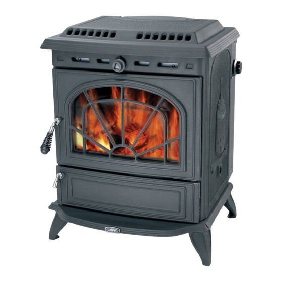
MINSTERLEY
SOLID FUEL BOILER
STOVE
INSTALLATION AND OPERATING INSTRUCTIONS
This appliance is hot while in operation and retains its heat for a long period of time after use.
Children, aged or infirm persons should be supervised at all times and should not be allowed to touch
the hot working surfaces while in use or until the appliance has thoroughly cooled.
When using the boiler stove in situations where children, aged and/or infirm persons are present a
fireguard must be used to prevent accidental contact with the stove. The fireguard should be
manufactured in accordance with BS 6539.
Advertisement
Table of Contents

Related Manuals for AGA MINSTERLEY


Summary of Contents for AGA MINSTERLEY
- Page 1 MINSTERLEY SOLID FUEL BOILER STOVE INSTALLATION AND OPERATING INSTRUCTIONS This appliance is hot while in operation and retains its heat for a long period of time after use. Children, aged or infirm persons should be supervised at all times and should not be allowed to touch the hot working surfaces while in use or until the appliance has thoroughly cooled.
-
Page 2: Table Of Contents
TABLE OF CONTENTS PAGE NO. General ............... 3 Handling . -
Page 3: General
THE MINSTERLEY SOLID FUEL CENTRAL HEATING STOVE INSTALLATION & OPERATING INSTRUCTIONS GENERAL The complete installation must be done in accordance with current Standards and Local When installing, operating and maintaining your Codes. It should be noted that the require- Minsterley Stove respect basic standards of fire ments and these publications may be super- safety. -
Page 4: Flues
Fig.4 Fig.3 2300 Ash Tray & Legs Assembly FLUES Flues should be vertical wherever possible and where a bend is necessary, it should not make an angle of more than 45 with the vertical. Horizontal flue runs should be avoided except in the case of a Soot Door Appliance back outlet from the appliance, when the length of... -
Page 5: Top Flue Exit
TOP FLUE EXIT CHIMNEY When connecting to a flue pipe it is necessary to Do not connect to a chimney serving another provide an access door in the pipe for flue and chim- appliance. ney cleaning. It is not possible to clean the chimney through the stove. -
Page 6: Location
LOCATION Fig.8 There are several conditions to be considered in selecting a location for your stove. a. Position in the area to be heated- central locations are usually best. 318mm b. Allowances for proper clearances to 1 /2 combustibles. 460mm INSTALLATION CLEARANCES 1 /9 Maintain at least the following clearances to all... -
Page 7: Specification
SPECIFICATION Fig.10 NOTE: Dimensions stated are in millimetres and may be subject to a slight +/- variation. TECHNICAL DATA Nominal Output Nominal Output Manufactured Room 5.0kW Wood logs Room 3.6kW Smokeless Fuel Water 7.3kW Water 7.5kW Typical refuelling intervals to obtain nominal out- Wood 1.5 hours puts... -
Page 8: Injector Tee
atmosphere. Cylinder and pipe work should be satisfied. Be aware that steam and boiling water will lagged to minimise heat loss. A drain cock should be expended from any open vent from the heating be fitted at the lowest point of the circuit. system probably in the roof space at the expansion tank. -
Page 9: Important Notes
13. Avoid contact with the appliance when in use as stove reaches very high operating temperatures. 14. This appliance should be regularly maintained by a competent service engineer. Use only replacement parts recommended by AGA. Making unauthorised modifications, or using unauthorised parts will invalidate your guarantee and may cause damage or injury. -
Page 10: Lighting
LIGHTING Before lighting the stove check with the installer that the installation work and commissioning checks described in the installation instructions have been carried out correctly and that the chimney has been swept clean, is sound and free from any obstructions. -
Page 11: Operating Instructions
OPERATING INSTRUCTIONS Fig.14 WOOD BURNING GRATE The standard grate in this appliance consisting of three moving firebars is suitable for burning all fuels but more suited to burning solid mineral fuel (coal). A flat grate with holes is provided to burn wood only. Do not use this plate to burn solid mineral fuels as it will overheat and damage will be caused. -
Page 12: Thermostat Operation
THERMOSTAT OPERATION Fig.18 Fig.16 Setting 0: Closed Overnight Burning Setting 1: 1/4 Open Setting 2: 1/2 Open Slowburning Setting 3: 3/4 Open Medium burning Setting 4: Full Open Maximum Heat DISPOSAL OF ASHES Your stove is provided with a steel ashpan. This Rotate the knob to give the required burning rate. -
Page 13: To Clean Chimney Back Outlet
TO REPLACE ROCKER OPERATING SLEEVE Fig. 20 1. Remove the 3 fire bars. 2. Lift the grate at the left hand end and remove it. 3. Withdraw the Rocker Operating Sleeve from under the boiler at the right hand side. 4. -
Page 14: In Case Of Fire
Fig.23 IN CASE OF FIRE Close all openings into the stove, watch for ignition of adjacent combustibles from over heated stove, or hot embers or sparks from chimney. VITREOUS ENAMEL CLEANING General cleaning must be carried out when the stove is cool. If this stove is finished in a high gloss vitreous enamel, to keep the enamel in the best condition observe the following tips:... -
Page 15: Exploded View
44. Primary Air Control Shaft Flue Blanking Plate 26. Righthand Front Brick 45. Spacer to Door Handle Right Hand Side Panel 27. Side Insulation 46. Aga Stove Badge Left Hand Side Panel 28. Grate Assembly 47. Fire Fence Front Frame 29. Thermostat Assembly 48. -
Page 16: Installation Check List
Ventilation & Combustion Air Requirements 12. The room in which the appliance is located should have an air vent of adequate size to support correct combustion (see Ventilation & Combustion Air Requirement Section for specific details). Aga, Station Road, Ketley, Telford, Shropshire, TF1 5AQ,...
Need help?
Do you have a question about the MINSTERLEY and is the answer not in the manual?
Questions and answers