
Related Manuals for Shinko PCD-33A


Summary of Contents for Shinko PCD-33A
- Page 1 INSTRUCTION MANUAL PROGRAMMABLE CONTROLLER PCD-33A 25 Whitefriars Drive Toronto, Ontario, Canada M3A 2L2 TEL: 416 444-0817 FAX: 416 444-2361 TOLL FREE: 1 888-4SHINKO Web Site: www.shinkona.com Email: sales@shinkona.com...
-
Page 2: Safety Precautions
• Be sure to follow the warnings, cautions and notices. If not, it could cause serious injury or malfunction. • Specifications of the PCD-33A and the contents of this instruction manual are subject to change without notice. • Care has been taken to assure that the contents of this instruction manual are correct, but if there are any doubts, mistakes or questions, please inform us through the shop where you purchased the unit. -
Page 3: Installation Precautions
Working or touching the terminal with the power switched ON may result in severe injury or death due to Electric Shock. • Be sure to turn OFF the power to the PCD-33A before cleaning. • Wipe the instrument using a soft dry cloth. -
Page 4: Table Of Contents
--- CONTENTS --- 1. Model names 1.1 Model names --------------------------------------------------------------------------- 5 1.2 Rated scale ----------------------------------------------------------------------------- 6 1.3 How to read the model nameplate ----------------------------------------------- 6 2. Name and functions of the sections 2.1 Name and displays ------------------------------------------------------------------ 7 2.2 Keys -------------------------------------------------------------------------------------- 8 3. -
Page 5: Model Names
1. Model names 1.1 Model names Alphanumeric character to represent the functions or type is applied to the [Example] PCD-33A R / M , C5 , – Option: Serial communication Input: Multi-input Control output: Relay contact output Standard models P C D – 3 3 A – / M,... -
Page 6: Rated Scale
Touching the terminal with the power switched ON may result in severe injury or death due to Electric Shock. Model nameplates are attached to the case and the left side of the inner assembly. [Example] Model name: PCD-33A-R/M PCD–33A–R/M Option: C5 (Serial communication) MULTI–RANGE Instrument number: Only indicated on the No. -
Page 7: Name And Functions Of The Sections
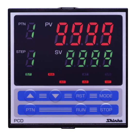
2 Name and functions of the sections 2.1 Name and Displays (11) (10) (Fig. 2.1-1) (1) PV display (Red) Indicates the Process variable (PV). When the setting mode is indicated, the setting item is indicated. (2) SV display (Green) Indicates the Setting value (SV). When the setting mode is indicated, the setting value is indicated. -
Page 8: Keys
2.2 Keys (18) (17) (12) (16) (13) (15) (14) (Fig. 2.2-1) (Increase key) : Increases the numeric value on the SV display or switches to (12) the next item. (13) (Decrease key) : Decreases the numeric value on the SV display or switches to the next item. -
Page 9: External Dimension And Panel Cutout
IP66 specification will not be fulfilled. 3.3 Mounting Mounting panel thickness is 1 to 15mm. Insert the PCD-33A from the front of the control panel. Slot the mounting bracket to the holes at the top and bottom of the case, and screw in place. -
Page 10: Wiring Connection
• Use the solderless terminal with an isolation sleeve that fits to the M3 screw when wiring the PCD-33A terminals. • The terminal block of the PCD-33A is designed to be wired from the left side. The lead wire must be inserted from the left side of the terminal, and fastened with the terminal screw. -
Page 11: Terminal Arrangement
Communication (RS-485) C5 4.1 Terminal arrangement or Setting value digital transmission SVTC YA(-) Ground Power supply 100 to 240V AC Event output 24V DC or 24V AC (EVT) YB(+) Control output Non-contact Relay contact External operation voltage input DC current Alarm 1 (A1) Isolated power Alarm 2 (A2) -
Page 12: Wiring Examples
(Fig.4.1-4) from Open to Closed. Closed to Open. 4.2 Wiring examples Caution PCD-33A-R/M When using a 24V AC/DC for the 3-phase power source, do not confuse the polarity when it is DC. 100 to 240V AC... - Page 13 For the relay contact output type (PCD-33A-R/M), it is recommended that a surge absorber be installed between the electromagnetic switch coils t o prevent the unit from harmful effects of unexpected level noise. PCD-33A-S/M Single phase 100 to 240V AC...
-
Page 14: Setup
Alarm action, Control action, etc. according to the users’ conditions. If the users’ specification is the same as the default value of the PCD-33A, it is not necessary to set up the controller. Proceed to Chapter “6. Operations” (p.21) Set up the controller after connecting terminals 2 and 3 for the power supply to this instrument, referring to “4. -
Page 15: Basic Operation For Setup
(19) Alarm 2 (A2) action delayed timer setting 0 seconds Sets Alarm 2 (A2) action delayed timer. (20) Event output function selection Time signal Selects an Event output type. output (21) Pattern end output time setting 0s (Continuous Sets pattern end output time. output) (22) Direct/Reverse action selection... -
Page 16: Setting Items In Auxiliary Function Setting Mode
5.3 Setting items in Auxiliary function setting mode 2 : Input type selection Selects a sensor type and temperature unit. Set the same sensor type as the users’. Selecting item: Refer to (Table 5.3-1) below. Default value: (K, -200 to 1370 ) (Table 5.3-1) Input types... - Page 17 • Default value: Scaling high limit value; 9999 Scaling low limit value; -1999 Decimal point place selection: (No decimal point) : PV filter time constant setting Sets the PV filter time constant. This reduces input fluctuation caused by noise. If the input changes in a step, set the time that reaches 63% of the step. However, if setting value is set too large, it affects control result due to delay of response.
- Page 18 (12) Alarm 1 (A1) action selection Selects Alarm 1 (A1) action type, referring to 8.5 Alarm 1 (A1) action (pp.48, 49). • Selecting item: No alarm action High limit alarm Low limit alarm High and Low limits alarm High and Low limit range alarm Process High alarm Process Low alarm High limit alarm with standby...
- Page 19 (20) Event output function selection Selects an Event output type from Time signal output, Pattern end output and Run output. When Event output is turned ON, EVT indicator is turned on, and terminals 12 and 13 are used for the Event output. •...
- Page 20 [Run output] (Fig. 5.3-3) This is outputted during the program control. Temperature Step 1 Step 2 Step 3 Time Program control end Run output OFF Run output ON Run output OFF (Fig. 5.3-3) (21) Pattern end output time setting Sets pattern end output time after pattern end output has been selected during Event output function selection.
-
Page 21: Operations
6. Operations Key operations for setup : Selects a program pattern number. : Increases or decreases the numeric number or switches the selecting item. key : Registers the settig value (numeric value) or selected item. By pressing the key, the controller reverts to the program standby mode or program control run mode. -
Page 22: Operation Flow Chart
6.1 Operation flow chart Power supply Automatically reverts to the Program standby (*1) (*2) mode after data is cleared. Program standby mode Data clearing Each time the key is Program control run mode pressed, the pattern number STEP on the PTN display changes. (Approx. - Page 23 BY pressing the key, the controller reverts to (*1) or (*2) from any mode. (Approx. 3s) (Approx. 3s) [Auxiliary function [Auxiliary function setting mode 1] setting mode 2] Setting value lock selection Input type selection Selected Selected STEP STEP value value Control output high limit Alarm 1 (A1) hysteresis...
-
Page 24: Operations
6.2 Operations (1) Turn the power to the controller ON. The sensor input character and temperature unit are indicated on the PV display and the input range high limit value is indicated on the SV display for approx. 3 seconds after the power is turned on. -
Page 25: Pattern (Step Sv/Time) Setting Mode
Actual temp. Program pattern 1 is selected. STEP Actual temp. Program pattern 2 is selected. STEP Actual temp. Program pattern 3 is selected. STEP Actual temp. Program pattern 9 is selected. STEP (4) Pattern (step SV/Time) setting mode This mode is available for the currently selected program pattern number. The following is an example of program pattern setting and its procedures. - Page 26 Press the key. Step 1 step SV is registered, and STEP Step 1 step time setting mode is selected. Step 1 step time setting Set the step time to (1:00) using key. STEP • Setting range: to 00:00 to 99:59 (Hour:Minute or Minute:Second) •...
-
Page 27: Alarm/Time Signal Setting Mode
(5) Alarm/Time signal setting mode Alarm/Time signal setting mode is available for the currently selected program pattern number. During program control run, settings are available only for the running pattern. Note : To go to the Alarm/Time signal setting mode, select an alarm action type except for No alarm action from Alarm 1 (A1) and Alarm 2 (A2) action selection in “5. -
Page 28: Pid Parameter Setting Mode
Pattern 1 Time signal output OFF time setting Sets Time signal output OFF time after the STEP program control run. Available only when Time signal output is selected from Event output function selection. • Setting range: 00:00 to 99.59 (Hour:Minute or Minute:Second) •... -
Page 29: Wait Parameter Setting Mode
Integral time setting Sets the integral time. STEP Off when set to 0 Not available for ON/OFF action • Setting range: 0 to 1000 seconds • Default value: 200 seconds Derivative time setting Sets the derivative time. STEP Off when set to 0 Not available for ON/OFF action •... - Page 30 [Program standby mode or program control run mode] Press the key for 3 seconds while Actual temp. holding down the key. STEP Wait parameter setting mode is selected, and (3s) Wait value setting item is indicated. [Wait parameter setting mode] Wait value setting Sets Pattern 1 Wait value.
-
Page 31: Auxiliary Function Setting Mode 1
[Program standby mode or program control run mode] Actual temp. STEP Auxiliary function setting mode 1 The settings in Auxiliary function setting mode 1 are applied to all program pattern numbers. [Program standby mode or program control run mode] Press the key for 3 seconds while Actual temp. - Page 32 • Default value: Shinko protocol Instrument number setting Selects the instrument number. STEP Set the PCD-33A to the instrument number individually when communicating by connecting plural PCD-33As. Available only when C5 (option) is applied. • Setting range: 0 to 95 •...
-
Page 33: Auxiliary Function Setting Mode
[Program standby mode or program control run mode] Actual temp. STEP (9) Auxiliary function setting mode 2 The settings in Auxiliary function setting mode 2 has already been completed in Chapter “5. Setup” (p.14). (10) Data clearing function This function returns all setting values to the default value. This function can only be carried out during program standby mode. -
Page 34: Running
7. Running [Before running] Before running the controller, check the mounting and wiring carefully, referring to “3. Mounting to control panel” (p.8) and “4. Wiring connection” (p.10) . Check that settings are applicable for the users’ conditions, referring to “5. Setup” (p.14). 7.1 How to set the program. - Page 35 PV start: When the program control starts, SV and step time are advanced to the PV, then the program control is performed. However, if the value set during the [Step SV setting when control starts] and the step SV are equal, or if the value set during the [Step SV setting when control starts] is higher than PV, PV start is cancelled, and SV start is adopted.
- Page 36 [Action after power failure is restored] (1) If the power failure occurs during program control run, the control resumes from the point at which power failure occurred. (2) If the power failure occurs during program standby mode, the control resumes from the program standby mode.
- Page 37 When the program pattern is falling [The Wait function is cancelled at (SV + Wait temperature)] Temperature Wait cancellation range The control proceeds to the next The step at which step at PV the Wait funtion was set SV=500 Wait temperature 10 C Time : Program pattern [Fig.
- Page 38 [Indication during Time signal action] If Time signal output is selected in the [Event output function selection], Event output is turned on during time signal output ON time. Time signal output ON time follows time signal output OFF time after the program control starts.
-
Page 39: How To Stop The Program Control
PTN display Selected program pattern number Actual temp. PV display : Current actual temperature STEP Step SV STEP display : Step number of the program control which is running SV display : Current step temperature RUN indicator : L indicator Run output is ON Lit while Other indicators: Lit or unlit according to the... -
Page 40: How To Switch To Fixed Value Control (Hold Function)
Temperature C Step 1 Step 2 Step 3 1000 Advance Time 01.00 (1 hour) 01.00 (1 hour) 00.40(40min.) Time signal Program control run Turned ON after 1 hour Turned OFF after 1 hour and 20 minutes and 50 minutes Setting Time signal OFF time: 1 hour and 20 minutes, Time signal ON time: 30 minutes (Fig. -
Page 41: How To Correct Pv (Sensor Correction Function)
[Time signal action during fixed value control] During the fixed value control, step time of the step at which the Hold function was set is regarded as (00:00). Time signal time measurement is carried out ignoring this step. Step number Temperature C Advance SV=500... -
Page 42: Pid Auto-Tuning
[Auxiliary function setting mode 1] Press the key 3 times. Sensor correction setting item is selected. STEP Selected value (Press 3 times) Set the sensor correction value with key. STEP Setting range: -100.0 to 100.0 For DC input, -1000 to 1000 (The placement of the decimal point follows the selection) Press the key. - Page 43 [PID auto-tuning performing conditions] (1) When processing temperature is lower than [setting value –20 (40 )] Fluctuation is applied at the temperature 20 (40 ) lower than the setting value. Temperature 20 (40 ) lower than the setting value (1) PID calculation Setting value (2) PID values decided...
- Page 44 [If P, I, D, ARW values cannot be changed] • If PID auto-tuning does not finish in 4 hours after it starts, PID auto-tuning is cancelled automatically, and P, I, D, ARW values return to the value set before the auto-tuning was performed.
-
Page 45: Control And Alarm Action 8.1 P, I, D, Arw Action
[How to cancel PID auto-tuning] Available only during PID auto-tuning Perform [PID auto-tuning Perform] Press the key while holding down Actual temp. key. STEP Step SV PID parameter setting mode is selected and AT Perform/Cancel item is indicated. [PID parameter setting mode] AT Perform/Cancel selection Press the key. -
Page 46: Derivative Time (D)
(3) Derivative time (D) Derivative action is used to restore the change in the processing temperature according to the rate of change. It reduces the amplitude of overshoot and undershoot width. If the derivative time is shortened, restoring value becomes small, and if the derivative time is made longer, an excessive returning phenomenon may occur and the control system may be oscillated. -
Page 47: On/Off Action
8.3 ON/OFF action Heating (reverse) action Cooling (direct) action Hysteresis Hysteresis Control action SV setting SV setting Relay contact output Non-contact 12V DC 0V DC 0V DC 12V DC voltage output DC current 20mA DC 20mA DC 4mA DC 4mA DC output Indication (OUT1) Green... -
Page 48: Alarm 1 (A1) And Alarm 2 (A2) Action
8.5 Alarm 1 (A1), Alarm 2 (A2) action High limit alarm Low limit alarm A1 hysteresis A1 hysteresis Alarm action + A1 + A1 set point set point set point set point setting setting + side + side Alarm output side side High/Low limits alarm... -
Page 49: Other Functions
High/Low limits alarm with standby A1 hysteresis Alarm action SV setting set point set point Alarm output : A1 output terminals 7 and 8 are connected (ON). A1 output terminals 7 and 8 are connected (ON) or disconnected (OFF). A1 output terminals 7 and 8 are disconnected (OFF). Standby functions. - Page 50 Automatic cold junction temperature compensation (Only thermocouple input type) This detects the temperature at the connecting terminal between the thermocouple and the instrument, and always keeps it set to the same status as when the reference (32 ). junction is located at 0 Burnout When the thermocouple or RTD input is burnt out, PV display blinks “...
-
Page 51: Specifications
10. Specifications 10.1 Standard specifications Model : Programmable controller Name : PCD-33A Mounting method : Flush Setting : Input system using membrane sheet key Display PV display : Red LED display 4 digits, character size, 18(H) x 8(W)mm SV display : Green LED display 4 digits, character size, 12.6(H) x6(W)mm... - Page 52 Setting resolution Temperature: Refer to Section “1.2 Rated scale” (p. 6). Time : 1 minute or 1 second Status after power failure is restored: The control resumes from the point at which power failure occurred. (Progressing time error after power failure is restored: Maximum 1 minute or 1 second.) Controlling action •...
- Page 53 : 100 to 240V AC 50/60Hz, or 24V AC/DC 50/60Hz For the supply voltage, 100 to 240V AC is standard. For 24V AC/DC, “1” is entered after the model name PCD-33A-x/M. Allowable voltage fluctuation: 100 to 240V AC: 85 to 264V AC...
-
Page 54: Optional Specifications
Circuit isolation configuration Communication Power Event output supply Isolated Control output (OUT) External operation Alarm 1 (A1) output Alarm 2 (A2) output or Input Isolated power output (P24) When the control output is non-contact voltage output type or DC current output type, between A to B and A to C are not isolated. -
Page 55: Troubleshooting
If option SVTC is added, external operation function is not available. If Setting value digital transmission is selected from Communication protocol selection, step SV of the PCD-33A can be transmitted digitally to a maximum of 31 units of Shinko controllers with communication function (option C5). - Page 56 • There may be equipment nearby producing an inductive fault or noise near the controller. PV display indicates • Internal memory is defective. Make inquiries to Shinko Technos or our dealers. <Keypad operation> Problem Presumed cause and solution It is impossible to •...
- Page 57 If the setting • SV high limit or low limit in Auxiliary function setting indication does not mode 1 may be set at the point the value does not change in the rated change. scale range even if Set it ( , or ) again while in Auxiliary keys are...
-
Page 58: Character Table
12. Character table Photocopiable material <Setting value/Time setting mode> Setting item Default value Data Step No. PV display Step 1 Step SV Step 1 Step time 00.00 (H:M) Step 2 Step SV Step 2 Step time 00.00 (H:M) Step 3 Step SV Step 3 Step time 00.00 (H:M) Step 4 Step SV... - Page 59 PV display Setting value lock Unlock SV (Setting value) high limit 1370 SV (Setting value) low limit -200 Sensor correction setting Communication protocol Shinko protocol Instrument number Communication speed 9600bps Parity Even Stop bit <Auxiliary function setting mode 2> Setting item...
-
Page 60: How To Make The Program Pattern Table
13. How to make the program pattern table Before setting the program, make a program pattern and data table. Copy the program pattern table and follow the procedure mentioned below. (1) Write down the program pattern number. (2) From Step 1, write down step SV and time of each step in sequence. (3) Write down Alarm 1 (A1) and Alarm 2 (A2) action points and Time signal output time. - Page 61 Program pattern (Pattern number) Step number Setting value (SV) Step temperature ( Step time (Hour:Minute) Wait function Used/Not used Wait value setting P (Proportional band) I (Integral time) D (derivative time) Anti-reset windup Proportional cycle Time signal output...
- Page 63 Revisions The manual number is noted at the lower right of the back cover. Print date Manual number Revision Jan. 2003 PCD31E1 First edition...
- Page 64 For any inquiries about this unit, please contact the shop where you purchased the unit after checking the following. [Example] • Model --------------------------- PCD-33A-R/M • Option --------------------------- C5 • Instrument number ---------- No. xxxxxx In addition to the above, please let us know the details of the malfunction, if any, and the operating conditions.
Need help?
Do you have a question about the PCD-33A and is the answer not in the manual?
Questions and answers