Table of Contents
Advertisement
Quick Links
Advertisement
Table of Contents

Related Manuals for Shinko PCB1


Summary of Contents for Shinko PCB1
- Page 1 PROGRAMMABLE CONTROLLER PCB1 INSTRUCTION MANUAL...
- Page 2 • Any unauthorized transfer or copying of this document, in part or in whole, is prohibited. • Shinko Technos Co., Ltd. is not liable for any damage or secondary damage(s) incurred as a result of using this product, including any indirect damage.
- Page 3 Warning • To prevent an electrical shock or fire, only Shinko or other qualified service personnel may handle the inner assembly. • To prevent an electrical shock, fire or damage to the instrument, parts replacement may only be undertaken by Shinko or other qualified service personnel.
- Page 4 2. Wiring Precautions Caution • Do not leave wire remnants in the instrument, as they could cause a fire or malfunction. • Use the solderless terminal with an insulation sleeve in which the M3 screw fits when wiring the instrument. •...
-
Page 5: Table Of Contents
Contents 1. Model................................7 1.1 Model ............................... 7 1.2 How to Read the Model Label ......................... 8 2. Name and Functions of Controller ........................9 3. Mounting to the Control Panel........................12 3.1 External Dimensions (Scale: mm) ......................12 3.2 Panel Cutout (Scale: mm)........................12 3.3 CT (Current Transformer) External Dimensions (Scale: mm)............... - Page 6 9.1.4 Advancing Program Step (Advance Function) ................93 9.1.5 Speeding up Program Step Time (Step Time Speed-up Function) ..........93 9.1.6 Changing Program Step SV and Step Time ................... 94 9.1.7 Ending Program (Pattern End Function)..................94 9.2 Performing Fixed Value Control......................95 9.2.1 Performing Fixed Value Control ......................
-
Page 7: Model
1. Model 1.1 Model PCB1 Relay contact output Control output Non-contact voltage output OUT1 Direct current output 100 to 240 V AC Power supply voltage 24 V AC/DC Input Multi-range Option 1 not needed. Event output EV2, or Heating/Cooling EV2(DR) -
Page 8: How To Read The Model Label
1.2 How to Read the Model Label The model label is attached to the right side of the case. ① ② ③ ④ ⑤ ⑥ ⑦ (Fig. 1.2-1) Description Example ① Terminal arrangement Terminal arrangement of PCB1R00-52 (*1) ② Model PCB1R00-52 ③... -
Page 9: Name And Functions Of Controller
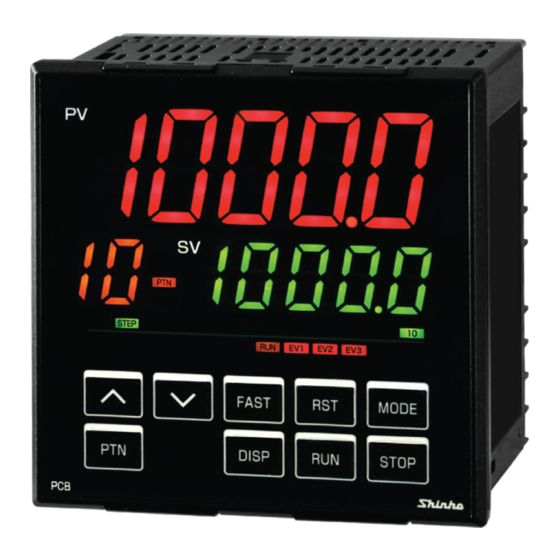
2. Name and Functions of Controller ① ② ③ ④ ⑤ ⑥ ⑦ ⑧ ⑯ ⑨ ⑮ ⑩ ⑪ ⑫ ⑬ ⑭ (Fig. 2-1) Display, Indicator Name Description ① PV Display Indicates process variable (PV) in RUN mode. (Red) Indicates setting characters in Setting mode. Flashes during Wait action or Program control Hold in program control. - Page 10 Action Indicator Name Description Lights up when control output OUT1 is ON. ⑦ OUT (Green) For direct current output, flashes corresponding to the MV in 125 ms cycles. Lights up during program control RUN. RUN (Orange) Flashes during Program control HOLD or Fixed value control. EV1 (Red) Lights up when Event output EV1 is ON.
- Page 11 Tool cable Top view of the case CMD-001 ⑰ (Fig. 2-2) Connector Name Description ⑰ Tool cable By connecting the Tool cable (CMD-001, sold separately), the following connector operations can be conducted from an external computer, using the Console software SWC-PCB101M. Tool cable connector is at the top of the instrument.
-
Page 12: Mounting To The Control Panel
3. Mounting to the Control Panel 3.1 External Dimensions (Scale: mm) Mounting Terminal cover Gasket bracket (sold separately) ( ): Size when mounting brackets or terminal cover (sold separately) are mounted. (Fig. 3.1-1) 3.2 Panel Cutout (Scale: mm) Caution If horizontal close mounting is used for the controller, IP66 specification (Drip-proof/Dust-proof) may be compromised, and all warranties will be invalidated. -
Page 13: Ct (Current Transformer) External Dimensions (Scale: Mm)
3.3 CT (Current Transformer) External Dimensions (Scale: mm) CTL-6-S-H (for 20 A) CTL-12-S36-10L1U (for 100 A) (Fig. 3.3-1) - 13 -... -
Page 14: Mounting To, And Removal From, The Control Panel
3.4 Mounting to, and Removal from, the Control Panel Caution As the case of the PCB1 is made of resin, do not use excessive force while tightening screws, or the case and mounting brackets could be damaged. The torque should be 0.1 N•m. -
Page 15: How To Remove The Mounting Bracket And Unit
(2) Attach the mounting brackets into the slots at the top and bottom of the case, and secure the controller in place with the screws. (Fig. 3.4.1-2) The torque is 0.1 N•m. Screw type mounting bracket (Fig. 3.4.1-2) 3.4.2 How to Remove the Mounting Bracket and Unit (1) Turn the power to the unit OFF, and disconnect all wires before removing the unit. -
Page 16: Wiring
4. Wiring Warning Turn the power supply to the instrument off before wiring or checking. Working on or touching the terminal with the power switched on may result in severe injury or death due to electrical shock. Caution • Do not leave wire remnants in the instrument, as they could cause a fire or malfunction. •... -
Page 17: Terminal Arrangement
4.1 Terminal Arrangement (Fig. 4.1-1) Terminal Code Description Supply voltage 100 to 240 V AC or 24 V AC/DC (For 24 V DC, ensure polarity is correct.) Control output OUT1 Event output EV1 Event output EV2 [EV2, EV3(DR) options] Control output OUT2 (EV2, DS, DA, EV3D options) Insulated power output 24 V DC (P24 option) Thermocouple input... -
Page 18: Lead Wire Solderless Terminal
When using a terminal cover (sold separately), make sure the longer side is on the back left and right side of the case. Pass the wires from terminal numbers 13 to 24 between terminal covers. Terminal cover PCB1 top view Mount the longer side of the cover to the back left and right. -
Page 19: Wiring
4 to 20 mA DC Load resistance: Max. 550 Non-contact voltage, Relay contact Direct current Number of Shinko SSR units when connected in parallel (for Non-contact voltage output): • SA-400 series: 5 units • SA-500 series: 2 units - 19 -... -
Page 20: Input
4.4.3 Input Each input wiring is shown below. Note: For DC voltage input, (+) side input terminal number of 0 to 5 V DC, 1 to 5 V DC, 0 to 10 V DC differs from that of 0 to 1 V DC. DC voltage Direct current, (0 to 5 V,... -
Page 21: Serial Communication
4.4.6 Serial Communication If the C5W or C5 option is ordered, Serial communication is available. Serial Communication (1) Serial Communication • When using USB communication cable CMC-001-1 (sold separately) USB communication cable PCB1 CMC-001-1 (sold separately) ⑩ YA(-) YA(-) YB(+) ⑪ YB(+) ⑫... - Page 22 PCA1, PCB1 (When ‘SV digital transmission’ is selected in [Communication protocol]) Update cycle: 250 ms Wiring For the PCB1 and controllers with the communication function, connect YA (-) to YA (-), YB (+) to YB (+), SG to SG terminal respectively. Up to 31 units can be connected.
-
Page 23: Ct Input 1 And Ct Input 2
4.4.7 CT Input 1 and CT Input 2 Current Transformer (CT) input is available when Heater burnout alarm output (C5W, EIW, W options) is ordered. Cannot be used for detecting heater current under phase control. Current Transformer (CT) Input 1 Current Transformer (CT) Input 2 Use the CT (current transformer) provided, and pass one lead wire of the heater circuit into the hole of the CT. -
Page 24: Transmission Output
4.4.8 Transmission Output If the EIT option is ordered, Transmission output is available. Specifications of Transmission output are shown below. Resolution 12000 4 to 20 mA DC Output Load resistance: Max. 550 Output accuracy Within 0.3% of Transmission output span 400 ms + Input sampling period (0%→90%) Response time Transmission Output... - Page 25 If ‘Pattern number selection’ is selected in [Event input DI1/DI2 allocation], Patterns 2 to 4 can be selected by ON (Closed) or OFF (Open) status of Event input DI1 and DI2. Pattern numbers selected by Event input have priority over pattern numbers selected by keypad operation.
-
Page 26: Outline Of Key Operation And Each Mode
5. Outline of Key Operation and Each Mode 5.1 Outline of Key Operation RUN Mode RUN key (*1) Program control STOP Program control RUN (in Standby) STOP key (1 sec) Monitor Mode (*2) PTN key PTN key PTN key Remaining time MV indication indication Setting Mode... - Page 27 Modes Mode Description If power is turned ON, the unit enters RUN mode. RUN mode Starts from Program control STOP (in Standby) or Program control RUN, depending on the status at power OFF. Indication differs depending on the status below. The PV Display indicates PV.
-
Page 28: Registering Settings And Selections
5.2 Registering Settings and Selections • How to increase/decrease setting values To increase or decrease the set value (numeric value), use the key. If the key is pressed with the FAST key simultaneously, makes the numeric value change faster. To switch the selection items, use the key. -
Page 29: Initial Settings
6. Initial Settings Setup (setting the Input type, Scaling high limit, Scaling low limit, Event output EV1 allocation, Step time unit, Power restore action, Direct/Reverse action, etc.) should be done before using this controller, according to the user’s conditions. Perform setup (or initial settings) in Engineering setting mode 2 and Control parameter setting mode. Initial setting items and their factory default values are shown below in (Table 6-1). - Page 30 Characters, Setting Item, Function, Setting Range Factory Default j//C -200 to 1000 r//C 0 to 1760 s//C 0 to 1760 b//C 0 to 1820 e//C -200 to 800 T//. C -200.0 to 400.0 n//C -200 to 1300 pl2C 0 to 1390 c//C C(W/Re5-26) 0 to 2315 Pt/.
- Page 31 Characters, Setting Item, Function, Setting Range Factory Default dp// Decimal point place • Selects decimal point place. / ///0 • Selection item: ///0 No decimal point //0. 0 1 digit after decimal point /0. 0 0 2 digits after decimal point 0.
- Page 32 Characters, Setting Item, Function, Setting Range Factory Default /018 Output by communication command: Communication command 8004H EV1 output 0 : OFF, 1: ON EV2 output 0 : OFF, 1: ON EV3 output 0 : OFF, 1: ON /019 RUN output: Turns ON during program control RUN.
- Page 33 Process high alarm Process low alarm EV1 hysteresis EV1 hysteresis EV1 value EV1 value (Fig. 6-7) (Fig. 6-8) High limit with standby alarm Low limit with standby alarm EV1 hysteresis EV1 hysteresis -EV1 value +EV1 value -EV1 value +EV1 value Alarm output is in...
- Page 34 Example of program pattern setting Pattern 1 Step number 1000 Step SV 1000 1000 Step time 0:30 1:00 0:40 1:00 2:00 Time signal output Program control RUN ON after 1 hour OFF after 50 minutes (e.g.) Time signal output setting Time signal output OFF time: 1 hour Time signal output ON time: 50 minutes (Fig.
- Page 35 Characters, Setting Item, Function, Setting Range Factory Default pret Power restore action • If the power fails during program control RUN, the controller can be operated / stop depending on the selection in [Power restore action]. • Selection item: stop Stops after power is restored: After power is restored, stops current program control, and returns to the Program control STOP (in Standby).
- Page 36 Characters, Setting Item, Function, Setting Range Factory Default Press the MODE key multiple times until the following characters appear. c/// OUT1 proportional cycle • Sets OUT1 proportional cycle. / ///3 • For the relay contact output type, if the proportional cycle time is decreased, the frequency of the relay action increases, and the life of the relay contact is shortened.
-
Page 37: Basic Settings And Operation
7. Basic Settings and Operation 7.1 Procedure of Basic Settings and Operation Power ON Program pattern setting Pattern setting Sets program pattern. (pp.43 -47) PID block, Wait value setting Control parameters Sets PID, ARW, etc. (pp.54 - 62) Sets Wait value, and Wait function Wait parameters (pp.63 - 66) Enabled/Disabled for each step. -
Page 38: Program Pattern Setting
7.2 Program Pattern Setting • Example of Program Pattern Setting Pattern 1 Step number 1000 Step SV 1000 1000 Step time 0:30 1:00 0:40 1:00 2:00 PID block number Wait function Enabled/Disabled Enabled Disabled Enabled Disabled Disabled (Fig. 7.2-1) Explanation of Program Pattern Step 1: After program control starts, control is performed so that SV gradually rises from 0 to 500 for 30 minutes. - Page 39 The operation method is described below, based on the program pattern, PID block and wait value settings. Power ON Power ON //25 RUN mode RUN mode Program control STOP (in Standby) 1 //// MODE key Program pattern setting temp Pattern setting mode Pattern setting Step 1 SV 1 ///0...
- Page 40 Step temp 2 SV 1 ///0 PTN/STEP temp 1 /500 PTN/STEP MODE time Step 2 time 1 00: 0 0 PTN/STEP time 01:00 1 01: 0 0 PTN/STEP MODE _pid Step block number 1 ///1 PTN/STEP block _pid 1 ///2 PTN/STEP MODE key Repeat settings up to ‘Step 5 PID...
- Page 41 //25 RUN mode RUN mode Program control STOP (in Standby) 1 //// key (3 sec) Wait value setting wait Wait parameter setting mode Wait parameter Wait value 1 ///0 wait 1 //10 MODE Step wait Wait function Enabled/Disabled 1 ---- PTN/STEP wait Wait function Enabled...
- Page 42 //25 Select a pattern number to perform. Press the PTN key to select a 1 //// pattern. Turn the load power ON, and press the RUN key for test operation. Test operation starts (Program control //25 Test operation RUN). 1 //25 (e.g.) Perform AT at Step 2 as its step SV is constant.
-
Page 43: Explanation Of Setting Items
8. Explanation of Setting Items Setting items for the following mode will be described: Pattern setting mode, Event setting mode, Control parameter setting mode, Wait parameter setting mode, Engineering setting mode 1, Engineering setting mode 2. 8.1 Setting Items in Pattern Setting Mode In Pattern setting mode, the following items are set: Step SV, Step time, PID block number, Number of repetitions, pattern link Settings are performed for the pattern selected when entering Pattern setting mode. - Page 44 Characters, Setting Item, Function, Setting Range Factory Default time Step 2 time • Sets Step 2 time. 1 00: 0 0 Step time is the processing time of the step. PTN/STEP indicator 2 • Setting range: lights up. ----, 00:00 to 99.59 (Time unit follows the selection in [Step time unit].) key is pressed at 00:00, ---- will appear.
- Page 45 Characters, Setting Item, Function, Setting Range Factory Default _pid Step 4 PID block number • Selects PID block number used for Step 4. 1 ///1 • Selection item: PTN/STEP indicator 4 1 to 10 lights up. temp Step 5 SV •...
- Page 46 Characters, Setting Item, Function, Setting Range Factory Default time Step 7 time • Sets Step 7 time. 1 00: 0 0 Step time is the processing time of the step. PTN/STEP indicator 7 • Setting range: lights up. ----, 00:00 to 99.59 (Time unit follows the selection in [Step time unit].) key is pressed at 00:00, ---- will appear.
- Page 47 Characters, Setting Item, Function, Setting Range Factory Default _pid Step 9 PID block number • Selects PID block number used for Step 9. 1 ///1 • Selection item: PTN/STEP indicator 9 1 to 10 lights up. temp Step 10 SV •...
-
Page 48: Setting Items In Event Setting Mode
8.2 Setting Items in Event Setting Mode Setting items in Event Setting Mode differs depending on the selection in [Event output EV allocation]. If 001 (High limit alarm) to 012 (High/Low limits alarm with standby independent alarm) are selected in [Event output EV allocation], EV alarm value will be set. - Page 49 • High/Low limit range alarm • High/Low limit range independent alarm EV1 hysteresis EV1 hysteresis EV1 value SV EV1 value EV1 low limit value EV1 high limit value (Fig. 8.2-5) (Fig. 8.2-6) • Process high alarm • Process low alarm EV1 hysteresis EV1 hysteresis EV1 value...
- Page 50 • Time signal output Time signal output OFF time and Time signal output ON time are set within one pattern total time. After program control starts, Time signal output activates during Time signal output ON time after Time signal output OFF time has elapsed. During Wait action or program control Hold, progress time of Time signal output stops.
- Page 51 • Before entering Event setting mode Select a pattern number with the PTN key before entering Event setting mode. • How to enter Event setting mode In RUN mode, press the MODE key for approx. 3 seconds to enter Event setting mode. Setting items in Event Setting mode are shown below.
- Page 52 Characters, Setting Item, Function, Setting Range Factory Default t1on TS1 output ON time • Sets TS1 output ON time. 1 00: 0 0 • Setting range: 00:00 to 99:59 (Time unit follows the selection in [Step time unit].) Available when /015 (Time signal output) is selected in [Event output EV1 allocation]. a2// EV2 alarm value •...
- Page 53 Characters, Setting Item, Function, Setting Range Factory Default t3of TS3 output OFF time • Sets TS3 output OFF time. 1 00: 0 0 • Setting range: 00:00 to 99:59 (Time unit follows the selection in [Step time unit].) Available when /015 (Time signal output) is selected in [Event output EV3 allocation]. t3on TS3 output ON time •...
-
Page 54: Setting Items In Control Parameter Setting Mode
8.3 Setting Items in Control Parameter Setting Mode In Control parameter setting mode, the following setting items can be set: AT Perform/Cancel, OUT1 proportional band, Integral time, derivative time, ARW, OUT2 proportional band (when EV2, DS, DA or EV3D option is ordered), Direct/Reverse action, Loop break alarm, etc. Setting data is common to all patterns. - Page 55 Characters, Setting Item, Function, Setting Range Factory Default p/// OUT1 proportional band • Sets OUT1 proportional band for the PID block number selected in [PID block 1 //10 number]. The PTN/STEP Display indicates the PID block number selected in [PID block number].
- Page 56 Characters, Setting Item, Function, Setting Range Factory Default c/// OUT1 proportional cycle • Sets OUT1 proportional cycle. / ///3 For relay contact output, if the proportional cycle time is decreased, the frequency of the relay action increases, and the life of the relay contact is shortened.
- Page 57 Characters, Setting Item, Function, Setting Range Factory Default orat OUT1 rate-of-change • Sets changing value of OUT1 MV for 1 second. / ///0 Setting the value to 0 disables this function. • About OUT1 rate-of-change: For Heating control, if PV is lower than SV, OUT1 MV is generally turned from OFF to ON as shown in (Fig.
- Page 58 Characters, Setting Item, Function, Setting Range Factory Default cact OUT2 cooling method • Selects OUT2 cooling method from air, oil or water cooling. / air/ OUT2 proportional band Air cooling Oil cooling Water cooling (Fig. 8.3-5) • Selection item: air/ Air cooling (Linear characteristics) oil/ Oil cooling (1.5th power of the linear characteristics)
- Page 59 Characters, Setting Item, Function, Setting Range Factory Default hysb OUT2 ON/OFF hysteresis • Sets OUT2 ON/OFF hysteresis. / //1. 0 Hysteresis OUT2 hysteresis (Fig. 8.3-6) • Setting range: 0.1 to 1000.0 DC voltage, current inputs: 1 to 10000 (The placement of the decimal point follows the selection.) Available when EV2 option {When /020 (Heating/Cooling control output) is selected in [Event output EV2 allocation]} is ordered, or when DS, DA or EV3D...
- Page 60 Characters, Setting Item, Function, Setting Range Factory Default db// Overlap/Dead band • Sets the overlap band or dead band for OUT1 and OUT2. / //0. 0 + Set value: Dead band – Set value: Overlap band Overlap band (When OUT1 and OUT2 are in PID control) OUT1 proportional band OUT2 proportional band Overlap band...
- Page 61 Characters, Setting Item, Function, Setting Range Factory Default Dead band (When OUT1 is in PID control, OUT2 is in ON/OFF control) OUT1 proportional band Hysteresis Dead band OUT1 OUT2 (Fig. 8.3-10) • Setting range: -200.0 to 200.0 DC voltage, current inputs: -2000 to 2000 (The placement of the decimal point follows the selection.) Available when EV2 option {When /020 (Heating/Cooling control output) is selected in [Event output EV2 allocation]} is ordered, or when DS, DA or EV3D...
- Page 62 Characters, Setting Item, Function, Setting Range Factory Default When OUT1 is OFF, the unit memorizes the previous value when OUT1 was Upon returning to set limits, the alarm will stop. • Setting range: 20 A: 0.0 to 20.0 A 100 A: 0.0 to 100.0 A Available when C5W, EIW, W option is ordered, and when OUT1 is relay contact output or non-contact voltage output type.
-
Page 63: Setting Items In Wait Parameter Setting Mode
8.4 Setting Items in Wait Parameter Setting Mode In Wait parameter setting mode, the following setting items can be set: Wait value, Wait function Enabled/Disabled for each step Settings are performed for the pattern number selected when entering Wait parameter setting mode. Setting data is common to all steps in each pattern. - Page 64 • Program pattern falling step: Wait value 10 Time When PV becomes 510 , Wait function is cancelled, proceeding to the next step. As PV is not in the range of [SV+Wait value], the Wait function is activated, and the unit does not proceed to the next step.
- Page 65 Characters, Setting Item, Function, Setting Range Factory Default wact Step 1 wait function Enabled/Disabled • Selects the wait function Enabled or Disabled at Step 1, based on the wait 1 ---- value set in [Wait value]. PTN/STEP • Selection item: indicator 1 ---- lights up.
- Page 66 Characters, Setting Item, Function, Setting Range Factory Default wact Step 7 wait function Enabled/Disabled • Selects the wait function Enabled or Disabled at Step 7, based on the wait 1 ---- value set in [Wait value]. PTN/STEP • Selection item: indicator 7 ---- lights up.
-
Page 67: Setting Items In Engineering Setting Mode 1
8.5 Setting Items in Engineering Setting Mode 1 In Engeering setting mode 1, the following setting items can be set: Set value lock, Sensor correction, PV filter time constant, Communication parameters (When C5W or C5 option is ordered) Setting data is common to all patterns. •... - Page 68 Characters, Setting Item, Function, Setting Range Factory Default sok/ Sensor correction coefficient • Sets sensor correction coefficient. / 1. 0 00 Sets slope of input value from a sensor. Corrected from to 700 . Corrected from to 340 Slope before correction Slope after correction ...
- Page 69 Communication protocol • Selects communication protocol. / noml • Selection item: noml Shinko protocol svt/ SV digital transmission (Shinko protocol) svtr SV digital reception (Shinko protocol) moda Modbus ASCII mode modr Modbus RTU mode Available when C5W or C5 option is ordered.
- Page 70 Available when C5W, C5 option is ordered, and when svtr [Set value digital reception (Shinko protocol)] is selected in [Communication protocol]. At this stage, settings for Engineering setting mode 1 are complete. Press the RST key. The unit reverts to RUN mode.
-
Page 71: Setting Items In Engineering Setting Mode 2
8.6 Setting Items in Engineering Setting Mode 2 In Engeering setting mode 2, the following setting items can be set: Input type, Scaling high limit, Scaling low limit, Event output EV allocation, Step time unit, Power restore action, etc. Setting data is common to all patterns. •... - Page 72 Characters, Setting Item, Function, Setting Range Factory Default t//. f -328.0 to 752.0 n//f -328 to 2372 pl2f 32 to 2534 c//f C(W/Re5-26) 32 to 4199 pt/. f Pt100 -328.0 to 1562.0 jpt. f JPt100 -328.0 to 932.0 pt/f Pt100 -328 to 1562 jptf JPt100...
- Page 73 Characters, Setting Item, Function, Setting Range Factory Default /006 Alarm output, High/Low limit range independent alarm /007 Alarm output, Process high alarm /008 Alarm output, Process low alarm /009 Alarm output, High limit with standby alarm /010 Alarm output, Low limit with standby alarm /011 Alarm output, High/Low limits with standby alarm /012...
- Page 74 Characters, Setting Item, Function, Setting Range Factory Default a1hy EV1 alarm hysteresis • Sets EV1 alarm hysteresis. / //1. 0 • Setting range: 0.1 to 1000.0 ( ), DC voltage, current inputs: 1 to 10000 (The placement of the decimal point follows the selection.) Available when any alarm from /001 (High limit alarm) to /012 (High/Low limits with standby independent alarm) is selected in [Event output EV1 allocation].
- Page 75 Characters, Setting Item, Function, Setting Range Factory Default /002 Alarm output, Low limit alarm /003 Alarm output, High/Low limits alarm /004 Alarm output, High/Low limits independent alarm /005 Alarm output, High/Low limit range alarm /006 Alarm output, High/Low limit range independent alarm /007 Alarm output, Process high alarm /008...
- Page 76 Characters, Setting Item, Function, Setting Range Factory Default a2za EV2 alarm value 0 Enabled/Disabled • When EV2 alarm value is 0 (zero), alarm action can be Enabled or Disabled. / no// • Selection item: no// Disabled yes/ Enabled Available when any alarm from /0 01 (High limit alarm) to /012 (High/Low limits with standby independent alarm) is selected in [Event output EV2 allocation] - excluding /007 (Process high alarm) and /008 (Process low alarm].
- Page 77 Characters, Setting Item, Function, Setting Range Factory Default evo3 Event output EV3 allocation • Selects Event output EV3 from the table below. / /000 • When changing Event output EV3, refer to Section “9.6 Items to be Initialized by Changing Settings” (p.104). •...
- Page 78 Characters, Setting Item, Function, Setting Range Factory Default When /001 (High limit alarm) to /012 (High/Low limit with standby independent alarm) or /015 (Time signal output) is selected, one output can be set to one event output. 013 (Heater burnout alarm output), /014 (Loop break alarm), /016 (Output When during AT) to /019 (RUN output) are selected, each output is common to multiple event outputs.
- Page 79 Characters, Setting Item, Function, Setting Range Factory Default • Selection item noml Energized revs De-energized Available when any alarm from /001 (High limit alarm) to /012 (High/Low limits with standby independent alarm) is selected in [Event output EV3 allocation]. evi1 Event input DI1 allocation •...
- Page 80 Characters, Setting Item, Function, Setting Range Factory Default evi2 Event input DI2 allocation • Selects Event input DI2 from the table below. / /000 • Selection item: Input ON Input OFF Event input function (Closed) (Open) /000 No event /001 Pattern number selection Refer to “About Event input”.
- Page 81 Characters, Setting Item, Function, Setting Range Factory Default tros Transmission output type • Selects the transmission output type. / pv// Converting the value (PV, SV, MV transmission) to analog signal every 125 ms, outputs the value in current or voltage. •...
- Page 82 Characters, Setting Item, Function, Setting Range Factory Default pret Power restore action • Selects the program status if a power failure occurs mid-program, and it is / stop restored. • Selection item: stop Stops after power is restored. After power is restored, stops current program control, and returns to the Program control STOP (in Standby).
- Page 83 Characters, Setting Item, Function, Setting Range Factory Default SV start Time 1:00 Program control RUN starts. Program control starts from the Step SV set in [Step SV when Program start starts]. (Fig. 8.6-8) • Selection item: pv// PV start: Only when Program control starts, the step SV and step time are advanced to the PV, then Program control starts.
- Page 84 Characters, Setting Item, Function, Setting Range Factory Default at_b AT bias • Sets bias value for the AT. / //20 AT point is automatically determined by the deviation between PV and SV. AT bias setting works only in Fixed value control. •...
-
Page 85: Clearing Data
8.7 Clearing Data If data is cleared, all data will revert to factory default values. Data can be cleared only in Program control STOP (in Standby). Data cannot be cleared during program control RUN. Caution Once data clear is executed, initial settings and each setting should be set again. (Cleared data cannot be restored.) In preparation for mistaken execution of data clear, please write down initial settings and other setting data in the data sheets at the end of this manual. -
Page 86: Operation
9. Operation 9.1 Performing Program Control 9.1.1 Performing Program Control (1) Before turning the power ON Check Sections “3. Mounting to the Control Panel (pp.12 - 15)” and “4. Wiring (pp.16 - 25)” before turning the power ON. (2) After turning the power ON Set necessary setting items after turning the power ON. - Page 87 If /001 (Pattern number selection) is selected in [Event input DI1 allocation] and [Event input DI2 allocation]: (e.g.) To select Pattern 4, close (ON) – , and – (Table 9.1.1-3) Pattern number Terminal number Event input DI1 OFF (Open) ON (Closed) OFF (Open) ON (Closed) Event input DI2...
- Page 88 [Program control start type] Program control start type can be selected in [Program control start type]. PV start: Only when program control starts, step SV and step time are advanced to the PV, then program control starts. However, if step SV set in [Step SV when program control starts] is higher than the PV (when PV start is initiated), then program control will start from the SV set in [Step SV when program control starts].
- Page 89 [Power Restore Action] If power fails during program control, the controller can be operated depending on the selection in [Power restore action]. Progressing time error when power is restored: 1 minute or 1 second • Stops after power is restored: After power is restored, stops current program control, and returns to Program control STOP (in Standby) status.
- Page 90 [Wait function] While program control is running, the program does not proceed to the next step until the deviation between PV and SV enters SV Wait value at the end of step. The PV Display and PTN/STEP Display flash while the Wait function is working. Explanation of Wait function •...
-
Page 91: Stopping Program Control
9.1.2 Stopping Program Control There are 2 methods for stopping program control: Using the STOP key or using Event input • Using the STOP key Press the STOP key for approximately 1 second during Program control RUN. Program control will stop, and revert to program control STOP (in Standby) status. •... -
Page 92: Suspending Program Control (Program Control Hold Function)
9.1.3 Suspending Program Control (Program Control Hold Function) During program control, progress of current step can be suspended (paused). Fixed value control is performed using the SV at the point of suspension. Pressing the RUN key cancels suspension, and program control resumes. To suspend program control, there are 2 methods: Using the key, or using Event input... -
Page 93: Advancing Program Step (Advance Function)
9.1.4 Advancing Program Step (Advance Function) Interrupts current step while program control is running, and proceeds to the beginning of the next step. If the Wait function is working, the Wait function will be cancelled, and will proceed to the beginning of the next step. -
Page 94: Changing Program Step Sv And Step Time
9.1.6 Changing Program Step SV and Step Time When step SV and step time are changed during program control RUN, they will change as follows. • When changing step SV from 500 to 700 Changing point Time Step number : Pattern before change : Pattern after change (Fig. -
Page 95: Performing Fixed Value Control
9.2 Performing Fixed Value Control 9.2.1 Performing Fixed Value Control Fixed value control (control action that indicating controllers are performing) is performed using the set step SV. To perform Fixed value control, set the step time (of the desired step SV) to ---- . (e.g.) Set Pattern 1, Step 1 SV to 500 , and set its step time to ---- . - Page 96 If /001 (Pattern number selection) is selected only in [Event input DI2 allocation], (e.g.) To select Pattern 2, close (ON) (Table 9.2.1-2) Pattern number Terminal number Event input DI2 OFF (Open) ON (Closed) * This number will be selected by keypad. If /001 (Pattern number selection) is selected in [Event input DI1 allocation] and [Event input DI2 allocation]: (e.g.) To select Pattern 4, close (ON)
-
Page 97: Finishing Fixed Value Control
9.2.2 Finishing Fixed Value Control There are 2 ways to finish Fixed value control: Using the STOP key, or using Event input • Using the STOP key Press the STOP key for approximately 1 second during Fixed value control. Fixed value control will stop, and the unit will revert to Program control STOP (in Standby). •... -
Page 98: Switching Indication Of The Sv Display
9.3 Switching Indication of the SV Display Press the PTN key to switch the indication of the SV Display. Each time the PTN key is pressed, switches the indication as follows. RUN mode /500 Step SV is indicated 1 /500 PTN key Monitor mode /500... -
Page 99: Performing At
9.4 Performing AT 9.4.1 Notice when Performing AT Notice • Perform the AT during the test operation. • During the AT, none of the setting items can be set. • If power failure occurs during AT, AT will stop. • If AT is cancelled during the process, P, I, D and ARW values will revert to the values before AT was performed. -
Page 100: At Action
9.4.2 AT Action In order to set each value of P, I, D and ARW automatically, the AT process should be made to fluctuate to obtain an optimal value. For DC voltage, current inputs, the AT process will fluctuate around the SV for conditions of [A], [B] and [C] below. -
Page 101: Performing At
9.4.3 Performing AT at// To perform AT, select (AT Perform) in [AT Perform/Cancel] in Control parameter setting mode. And press the RST key. Basic Procedure Setting Details /500 During program control RUN RUN mode 1 /500 + MODE at// Control parameter Control parameter setting mode AT Perform/Cancel setting mode... -
Page 102: Input Value Correction
9.5 Input Value Correction Input value can be corrected in [Sensor correction coefficient] and [Sensor correction] in Engineering setting mode 1. In [Sensor correction coefficient], set the slope of temperature change. In [Sensor correction], set the difference between temperatures before correction and after correction. - Page 103 (Example) Setting Sensor correction coefficient to 0.800, and Sensor correction to 100.0 Basic procedure Setting details /500 RUN mode RUN mode During program control RUN 1 /500 + MODE (3 sec) lock Engineering setting Engineering setting mode 1 Set value lock mode 1 / ---- MODE...
-
Page 104: Items To Be Initialized By Changing Settings
9.6 Items to be Initialized by Changing Settings If settings are changed, the following items will be initialized. : Initialized : Not initialized Setting item to be changed Event Event Event Input output output output Transmission Type output Item to be initialized allocation allocation allocation... -
Page 105: Action Explanation
10. Action Explanation 10.1 OUT1 Action Reverse (Heating) action Direct (Cooling) action Proportional band Proportional band Control action ⑮ ⑮ ⑮ ⑮ ⑮ ⑮ Relay contact output ⑯ ⑯ ⑯ ⑯ ⑯ ⑯ Cycle action is performed Cycle action is performed according to deviation. -
Page 106: Heater Burnout Alarm Action
10.3 Heater Burnout Alarm Action Heater burnout alarm action Heater burnout alarm value Small Large Load current ⑰ ⑰ Output ⑱ ⑱ Indicator Unlit ⑰, ⑱ Event output EV1 terminal numbers: ⑲, ⑳ Event output EV2 terminal numbers: Event output EV3 terminal numbers: ⑥, ⑦... -
Page 107: Alarm Action
10.4 Alarm Action High limit alarm Low limit alarm EV1 hysteresis EV1 hysteresis Alarm action -EV1 value +EV1 value -EV1 value +EV1 value +side +side Alarm output -side -side High/Low limits independent alarm High/Low limits alarm EV1 hysteresis EV1 hysteresis Alarm action EV1 value... - Page 108 • EV1 value, EV1 high limit value, and EV1 hysteresis represent EV1 alarm value, EV1 high limit alarm value and EV1 alarm hysteresis respectively. For EV2/EV3, read “EV2/EV3” for “EV1”. • EV1 indicator lights up when Event output EV1 terminals 17 and 18 are ON, and turns off when their output terminals 17 and 18 are OFF.
-
Page 109: Out2 (Heating/Cooling Control) Action
10.5 OUT2 (Heating/Cooling Control) Action (Cooling P-band) Heating P-band Control Heating (Cooling action action action) ⑮ ⑮ ⑮ Relay contact output ⑯ ⑯ (OUT1) ⑯ Cycle action is performed according to deviation. ⑮ ⑮ ⑮ Non-contact 12 V DC 12/0 V DC 0 V DC voltage output ⑯... -
Page 110: Out2 (Heating/Cooling Control) Action (When Setting Dead Band)
10.6 OUT2 (Heating/Cooling Control) Action (When Setting Dead Band) : Turns ON (Lit) or OFF(Unlit). : Represents Heating control action. : Represents Cooling control action. - 110 -... -
Page 111: Out2 (Heating/Cooling Control) Action (When Setting Overlap Band)
10.7 OUT2 (Heating/Cooling control) Action (When Setting Overlap band) Heating P-band (Cooling P-band) Overlap band Control Heating (Cooling action action action) ⑮ ⑮ ⑮ Relay contact output (OUT1) ⑯ ⑯ ⑯ Cycle action is performed according to deviation. ⑮ ⑮ ⑮... -
Page 112: Specifications
11. Specifications 11.1 Standard Specifications Rating Rated scale Input Scale Range Resolution -200 to 1370 -328 to 2498 -200.0 to 400.0 -328.0 to 752.0 -200 to 1000 -328 to 1832 0 to 1760 32 to 3200 0 to 1760 32 to 3200 0 to 1820 32 to 3308 -200 to 800... - Page 113 Output Control Relay contact Control capacity: 3 A 250 V AC (resistive load) output 1 A 250 V AC (inductive load cosφ=0.4) OUT1 Electrical life: 100,000 cycles Minimum applicable load: 10 mA 5 V DC Non-contact 12 V DC 15% voltage Max.
- Page 114 Power PCB1 00- PCB1 10- Power supply Model Power supply 100 – 240 V AC, 50/60 Hz 24 V AC/DC, 50/60 Hz Allowable 85 – 264 V AC 20 – 28 V AC/DC fluctuation range Power consumption Power supply Power consumption 100 –...
- Page 115 When EIW or W option is ordered: Electrically insulated POWER SUPPLY OUT1 (Input) OUT2 When EIW option is ordered When W option is ordered (Fig. 11.1-2) When OUT1 and OUT2 are a non-contact voltage output or direct current output, OUT1 is not electrically insulated from OUT2. Insulation resistance: 10 M min., at 500 V DC - 115 -...
- Page 116 When EIT or EI option is ordered: Electrically insulated POWER SUPPLY OUT1 (Input) OUT2 TA: When EIT option is ordered. EV3: When EI option is ordered. (Fig. 11.1-3) When OUT1 and OUT2 are a non-contact voltage output or direct current output, OUT1 is not electrically insulated from OUT2.
- Page 117 Recommended Environment -10 to 55 (However, non-condensing or no icing) Ambient temperature Ambient humidity 35 to 85 %RH (However, non-condensing) Environmental RoHS directive compliant specification Performance Base accuracy At ambient temperature 23 (for a single unit mounting) Thermocouple Within 0.2% of each input span 1 digit However, R, S input, 0 to 200 (32 to 392 ): Within (12 )
- Page 118 PTN/STEP Indicates the pattern number or step number. Display Each time the DISP key is pressed, the PTN/STEP Display and the PTN/STEP indicator alternately indicate the pattern number and step number. Flashes during Wait action, or when the step number is indicated. If ‘SV digital reception’...
- Page 119 Setting Structure Function key UP key In setting mode, increases the numerical value. By pressing for approx. 1 sec during program control RUN, time progress pauses, and Program control Hold function initiates.) DOWN key In setting mode, decreases the numerical value. FAST In setting mode, makes the numeric value change FAST key...
- Page 120 Control Performance Control action • PID control action (with AT function) • PI control action (When derivative time is set to 0.) • PD control action (When integral time is set to 0.) • P control action (When integral and derivative time are set to 0.) •...
- Page 121 Program control start type Selects program control start type. PV start: Only when program control starts, the step SV is advanced to the PV, then program control starts. PVR start: When program control starts and in pattern repeating, the step SV is advanced to the PV, then program control starts.
- Page 122 When Loop break alarm is selected in [Event output EV allocation], Loop break alarm detects actuator trouble (heater burnout, heater adhesion) or sensor burnout. 0 to 200 minutes Loop break alarm time Thermocouple, RTD input without decimal point: 0 to 150 Loop break alarm span Thermocouple, RTD input with decimal point: 0.0 to 150.0 DC voltage, current input: 0 to 1500 (The placement of the decimal...
- Page 123 Attached Functions Sensor correction Sets slope of input value from a sensor. coefficient Sensor correction Corrects the input value from a sensor. Set value lock Locks the set values to prevent setting errors. Power failure The setting data is backed up in the non-volatile IC memory. countermeasure Self-diagnosis The CPU is monitored by a watchdog timer, and if an abnormal status...
- Page 124 Burnout If burnout occurs, the following will be performed depending on the selection in [Error indication]. If Disabled is selected in [Error indication]: If PV has exceeded Indication range and Control range, the PV Display flashes ~~~~. OUT1 and OUT2 are turned OFF (OUT1 low limit value for direct current output, OUT2 low limit value for DA, EV3DA).
- Page 125 If Alarm output, Heater burnout alarm output or Loop break alarm output is selected in [Event output allocation], Event output will be turned ON under the alarm active conditions. Burnout is enabled even in Program control STOP (in Standby) status. However, Event output is not turned ON.
-
Page 126: Optional Specifications
11.2 Optional Specifications Output will be turned ON or OFF depending on the Event conditions Event output EV2 selected in [Event output EV2 allocation]. [EV2, EV3(DR) options] One output can be selected from the following: Alarm output, Heater burnout alarm output, Loop break alarm output, Time signal output, Output during AT, Pattern end output, Output by communication command, RUN output, Heating/Cooling control Relay contact output... - Page 127 • PCD-33A with the SVTC (SV digital transmission) option • PCA1 for which ‘SV digital transmission’ is selected in Communication protocol] • PCB1 for which ‘SV digital transmission’ is selected in [Communication protocol] PCB1 Controller with communication function (Max. 31 units)
- Page 128 Heater burnout alarm Monitors heater current with CT (current transformer), and detects heater burnout. (C5W, EIW, W options) output, for which Heater burnout alarm is selected in [Event output allocation], will be turned ON or OFF. This alarm is also activated when the input is burnt out. Rated current: 20 A, 100 A (Must be specified when ordering.) Single-phase: Detects burnout with CT1 input.
-
Page 129: Troubleshooting
12. Troubleshooting Warning Turn the power supply to the instrument off before wiring or checking. Working on or touching the terminal with the power switched on may result in severe injury or death due to electrical shock. Moreover, the instrument must be grounded before the power supply to the instrument is turned on. - Page 130 Problem Possible Cause Solution Check whether the input terminals Connect the sensor terminals to the of thermocouple, RTD or DC instrument input terminals securely. voltage (0 to 1 V DC) are securely mounted to the instrument input terminals. PV has dropped below the Check the input signal source and wiring of The PV Display Indication range and Control...
-
Page 131: Key Operation
Problem Possible Cause Solution The PV Display Check whether the input signal Check the input signal wires of direct keeps indicating wire for direct current (0 to 20 mA current (0 to 20 mA DC) and DC voltage the value set in DC) and DC voltage (0 to 5 V DC, (0 to 5 V DC, 0 to 10 V DC). -
Page 132: Control
12.3 Control Problem Possible Cause Solution Even though The step time of the performing Set the step time to a suitable value. program control pattern number is set to 00:00. is executed, the control is advanced and the program is finished soon. -
Page 133: Character Table
13. Character Table • Explanation of Setting Item Upper left: PV Display Indicates setting item characters. Lower left: PTN/STEP Display, SV Display The PTN/STEP Display indicates the selected pattern number, and indication is different depending on the setting item. The SV Display indicates factory default. Right side: Indicates the setting item, explanation of its function, and setting range. -
Page 134: Pattern Setting Mode
13.2 Pattern Setting Mode Characters, Setting Item, Setting Range Data Factory Default temp Step 1 SV Scaling low limit to Scaling high limit 1 ///0 PTN/STEP indicator 1 lights. time Step 1 time ---- 00:00 to 99.59 (Time unit follows the selection in [Step time 1 00: 0 0 unit].) PTN/STEP... - Page 135 Characters, Setting Item, Setting Range Data Factory Default temp Step 4 SV Scaling low limit to Scaling high limit 1 ///0 PTN/STEP indicator 4 lights. time Step 4 time ---- 00:00 to 99.59 (Time unit follows the selection in [Step time 1 00: 0 0 unit].) PTN/STEP...
- Page 136 Characters, Setting Item, Setting Range Data Factory Default temp Step 7 SV Scaling low limit to Scaling high limit 1 ///0 PTN/STEP indicator 7 lights. time Step 7 time ---- 00:00 to 99.59 (Time unit follows the selection in [Step time 1 00: 0 0 unit].) PTN/STEP...
- Page 137 Characters, Setting Item, Setting Range Data Factory Default temp Step 10 SV Scaling low limit to Scaling high limit 1 ///0 PTN/STEP indicator 10 lights. time Step 10 time ---- 00:00 to 99.59 (Time unit follows the selection in [Step time 1 00: 0 0 unit].) PTN/STEP...
-
Page 138: Event Setting Mode
13.3 Event Setting Mode Characters, Setting Item, Setting Range Data Factory Default a1// EV1 alarm value High limit alarm -(Input span) to Input span (*1) 1 ///0 Low limit alarm -(Input span) to Input span (*1) High/Low limits alarm 0 to Input span (*1) High/Low limits independent alarm 0 to Input span... - Page 139 Characters, Setting Item, Setting Range Data Factory Default t2of TS2 output OFF time Setting range: 1 00: 0 0 00:00 to 99:59 (Time unit follows the selection in [Step time unit].) Available when /015 (Time signal output) is selected in [Event output EV2 allocation].
-
Page 140: Control Parameter Setting Mode
13.4 Control Parameter Setting Mode Characters, Setting Item, Setting Range Data Factory Default at// AT Perform/Cancel ---- AT Cancel / ---- AT// AT Perform pblk PID block number 1 to 10 / ///1 p/// OUT1 proportional band Setting range: 1 //10 Thermocouple, RTD input without decimal point: 0 to input span Thermocouple, RTD input with decimal point: 0.0 to input span DC voltage, current inputs: 0.0 to 1000.0%... - Page 141 Characters, Setting Item, Setting Range Data Factory Default p_b/ OUT2 proportional band Setting range: 1 //10 Thermocouple, RTD input without decimal point: 0 to Input span Thermocouple, RTD input with decimal point: 0.0 to Input span DC voltage, current inputs: 0.0 to 1000.0% Available when EV2 option {/020 (Heating/Cooling control output) is selected in [Event output EV2 allocation]} is ordered, or when DS, DA or EV3D option is...
- Page 142 Characters, Setting Item, Setting Range Data Factory Default h1// Heater burnout alarm 1 value Setting range: / //0. 0 20 A: 0.0 to 20.0 A h1// and CT1 100 A: 0.0 to 100.0 A current value are alternately Available when C5W, EIW, W option is ordered, and OUT1 is relay contact output indicated.
-
Page 143: Wait Parameter Setting Mode
13.5 Wait Parameter Setting Mode Characters, Setting Item, Setting Range Data Factory Default wait Wait value Setting range: 0 to 20% of input span 1 ///0 (*) DC voltage, current inputs: 0 to 20% of scaling span (The placement of the decimal point follows the selection.) wact Step 1 wait function Enabled/Disabled ---- Disabled... - Page 144 Characters, Setting Item, Setting Range Data Factory Default wact Step 10 wait function Enabled/Disabled ---- Disabled 1 ---- use/ Enabled PTN/STEP indicator 10 lights Not available if Wait value is set to 0 or 0.0. - 144 -...
-
Page 145: Engineering Setting Mode 1
/ //0. 0 cmsl Communication protocol noml Shinko protocol / noml svt/ Set value digital transmission (Shinko protocol) svtr Set value digital reception (Shinko protocol) moda Modbus ASCII mode modr Modbus RTU mode Available when C5W or C5 option is ordered. - Page 146 DC voltage, current inputs: 20% of scaling span (The placement of the decimal point follows the selection.) Available when C5W, C5 option is ordered, or when svtr [Set value digital reception (Shinko protocol)] is selected in [Communication protocol]. - 146 -...
-
Page 147: Engineering Setting Mode 2
13.7 Engineering Setting Mode 2 Characters, Setting Item, Setting Range Data Factory Default sens Input type k//C -200 to 1370 / k//C k//. C -200.0 to 400.0 j//. C -200 to 1000 r//C 0 to 1760 s//C 0 to 1760 b//C 0 to 1820 e//C... - Page 148 Characters, Setting Item, Setting Range Data Factory Default stll Scaling low limit Setting range: Input range low limit to Scaling high limit / -200 DC voltage, current inputs: -2000 to 10000 (The placement of the decimal point follows the selection.) dp// Decimal point place ///0...
- Page 149 Characters, Setting Item, Setting Range Data Factory Default a1hy EV1 alarm hysteresis Setting range: 0.1 to 1000.0 ( ), / //1. 0 DC voltage, current inputs: 1 to 10000 (The placement of the decimal point follows the selection.) Available when any alarm from /001 (High limit alarm) to /012 (High/Low limits with standby independent alarm) is selected in [Event output EV1 allocation].
- Page 150 Characters, Setting Item, Setting Range Data Factory Default a2za EV2 alarm value 0 Enabled/Disabled no// Disabled / no// yes/ Enabled Available when any alarm from /0 01 (High limit alarm) to /012 (High/Low limits with standby independent alarm) is selected in [Event output EV2 allocation] - excluding /007 (Process high alarm) and /008 (Process low alarm].
- Page 151 Characters, Setting Item, Setting Range Data Factory Default a3za EV3 alarm value 0 Enabled/Disabled no// Disabled / no// yes/ Enabled Available when any alarm from /0 01 (High limit alarm) to /012 (High/Low limits with standby independent alarm) is selected in [Event output EV3 allocation] - excluding /007 (Process high alarm) and /008 (Process low alarm].
- Page 152 Characters, Setting Item, Setting Range Data Factory Default evi2 Event input DI2 allocation Input ON Input OFF / /000 Event input function (Closed) (Open) /000 No event /001 Pattern number selection /002 Direct/Reverse action Direct action Reverse action /003 Program control STOP RUN/STOP /004...
- Page 153 Characters, Setting Item, Setting Range Data Factory Default pret Power restore action stop Stops after power is restored. / stop After power is restored, stops current program control, and returns to the Program control STOP (in Standby). cont Continues (resumes) after power is restored. Continues (resumes) previous program control after power is restored.
-
Page 154: Data Clear
Characters, Setting Item, Setting Range Data Factory Default time Indication time Setting range: 00:00 to 60:00 (Minutes : Seconds) / 00: 0 0 When set to 00:00, Displays remain ON. edif Error indication no// Disabled / no// yes/ Enabled 13.8 Data Clear Characters, Setting Item, Setting Range Data... -
Page 155: Making Program Pattern Table And Data Table
14. Making Program Pattern Table and Data Table Before setting program, make a program pattern table and data table. 14.1 Making Program Pattern Table Please make a copy of the program pattern table (p.157), and follow the procedure below. (1) Write a step SV, step time, PID block number, Wait function Enabled/Disabled for each step from Step 1 in numerical order. -
Page 156: Making Data Table
Data OUT1 proportional cycle 15 sec OUT2 proportional cycle 15 sec Number of repetitions Pattern link Pattern link Disabled Communication protocol Shinko protocol Instrument number Communication speed 38400 bps Data bit/Parity 7 bits/Even Stop bit 1 bit Response delay time... - Page 157 Program Pattern Table Please make a copy of this table for use. Pattern number Step number Step SV Step time PID block number Wait function Enabled/Disabled - 157 -...
- Page 158 Data Table Please make a copy of this table for use. • PID block PID Block OUT1 Integral Derivative OUT2 number P-band time time P-band • Wait value Wait value Wait value is common to all steps for each pattern. •...
-
Page 159: Key Operation Flowchart
15. Key Operation Flowchart - 159 -... - Page 160 ***** Inquiries ***** For any inquiries about this unit, please contact our agency or the vendor where you purchased the unit after checking the following. [Example] • Model ------------------------------ PCB1R00-52 • Option ----------------------------- EV3(DR), C5W(100A) • Serial number ------------------- No. 173F05000 In addition to the above, please let us know the details of the malfunction, or discrepancy, and the operating conditions.
Need help?
Do you have a question about the PCB1 and is the answer not in the manual?
Questions and answers