Table of Contents
Advertisement
Advertisement
Table of Contents

Related Manuals for Shinko JCR-33A


Summary of Contents for Shinko JCR-33A
- Page 1 DIGITAL INDICATING CONTROLLER JCR-33A, JCD-33A INSTRUCTION MANUAL...
- Page 2 Thank you for purchasing our Digital Indicating Controller JCR-33A or JCD-33A. This manual contains instructions for the mounting, functions, operations and notes when operating the JCR-33A and JCD-33A. To prevent accidents arising from the misuse of this controller, please ensure the operator receives this manual.
- Page 3 • Any unauthorized transfer or copying of this document, in part or in whole, is prohibited. • Shinko Technos CO., LTD. is not liable for any damage or secondary damage(s) incurred as a result of using this product, including any indirect damage.
- Page 4 • Use a solderless terminal with an insulation sleeve in which an M3 screw fits when wiring the JCD-33A or JCR-33A. • The terminal block of this instrument is designed to be wired from the left side. The lead wire must be inserted from the left side of the terminal, and fastened with the terminal screw.
-
Page 5: Table Of Contents
3.1 Site selection ------------------------------------------------------------------------- 9 3.2 External dimensions -------------------------------------------------------------- 10 3.3 Panel cutout ------------------------------------------------------------------------- 10 3.4 CT (current transformer) external dimensions ------------------------------ 11 3.5 Mounting (Common to JCR-33A and JCD-33A) --------------------------- 11 4. Wiring 4.1 Terminal arrangement ------------------------------------------------------------ 12 4.2 Wiring example -------------------------------------------------------------------- 13 5. -
Page 6: Model
Relay contact output 96 x 96 x 100mm Standard specifications -3 3 A - Series JCR-33A: W48 x H96 x D100mm name JCD-33A: W96 x H96 x D100mm Alarm 1 (A1) Alarm type can be selected by keypad . *1... -
Page 7: Rated Input
1.2 Rated input Input type Input range Resolution –200 to 1370 –320 to 2500 1 ( ) –199.9 to 400.0 –199.9 to 750.0 0.1 ( ) –200 to 1000 –320 to 1800 1 ( ) 0 to 1760 0 to 3200 1 ( ) 0 to 1760 0 to 3200... -
Page 8: Name And Functions Of Sections
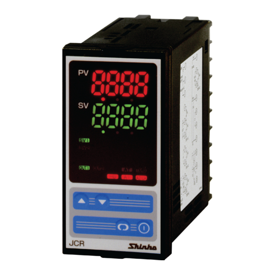
2. Name and functions of sections (10) (10) (11) (11) (14) (14) (12) (15) (15) (12) (13) (13) (Fig. 2-1) (1) PV display Indicates the PV or setting characters in the setting mode with the red LED. (2) SV display Indicates the SV, the MV or each set value in the setting mode with the green LED. -
Page 9: Mounting To The Control Panel
(11) A2/LA indicator When A2 output or LA output is ON, the red LED lights. (12) Increase Key ( Increases numeric values. (13) Decrease Key ( Decreases numeric values. (14) Mode Key ( Switches the setting mode and registers the set (or selected) value. [Set (or selected) value are registered by pressing the Mode Key.] (15) OUT/OFF Key ( ) Switches Control output OFF or Auto/Manual control. -
Page 10: External Dimensions
3.2 External dimensions (Scale: mm) • JCR-33A Gasket Screw type mounting bracket 11.5 98.5 (Fig. 3.2-1) • JCD-33A Gasket Screw type mounting bracket 11.5 98.5 (Fig. 3.2-2) 3.3 Panel cutout (Scale: mm) • JCR-33A +0.5 n x 48-3 Lateral close mounting, n: Number of units mounted... -
Page 11: Ct (Current Transformer) External Dimensions
CTL-6S (for 5A, 10A, 20A) CTL-12-S36-10L1U (for 50A) 2-M3 (Fig. 3.4-1) 3.5 Mounting (Common to JCR-33A and JCD-33A) Warning As the case is made of resin, do not use excessive force while screwing in the mounting bracket, or the case could be damaged. -
Page 12: Wiring
(Fig. 3.5-1) 4. Wiring Warning Turn the power supply to the instrument off before wiring or checking. Working on or touching the terminal with the power switched on may result in severe injury or death due to Electric Shock. Moreover, the instrument must be grounded before the power supply to the instrument is turned on. -
Page 13: Wiring Example
Caution • The terminal blocks of the JCR-33A and JCD-33A are designed to be wired from the left side. The lead wire must be inserted from the left side of the terminal, and fastened with the terminal screw. • Dotted lines are optional. Option terminals are equipped only when the option is added. - Page 14 (Fig. 4.2-2) • For a 24V AC/DC of power source, do not confuse polarity when using a direct current (DC). • Number of connectable units in parallel when using Shinko SSR: SA-300-Z series : 4 units SA-400 series : 5 units...
-
Page 15: Setup
5. Setup For the thermocouple and RTD input, the sensor input characters and temperature unit are indicated on the PV display, and the input range high limit value is indicated on the SV display for approximately 3 seconds after the power is turned on. (Table 5-1) For DC input, the sensor input characters are indicated on the PV display and the scaling high limit value is indicated on the SV display for approximately 3 seconds after the power is turned on. -
Page 16: Operation Flowchart
Set an Input type, Alarm (type, value, etc.) and SV, following the procedures below. Setting item numbers (1) to (7) are indicated on the flowchart. [Step 1 Operation before Run] Turn the load circuit power OFF, and turn the power supply to the JCD, JCR-33A ON. - Page 17 Alarm type Input type (character indication) and range –200 to 1370 –320 to 2500 (High limit alarm): The alarm action is the deviation setting from the SV. The alarm –199.9 to 400.0 –199.9 to 750.0 is activated if the input value reaches the high limit set value. –200 to 1000 –320 to 1800 (Low limit alarm): The alarm action is the...
-
Page 18: Main Setting Mode
5.2 Main setting mode Press the key in the PV/SV display mode to enter the Main setting mode. The SV can be increased or decreased by pressing the key. If the key is pressed, the SV is registered, and the controller will revert to the PV/SV display mode. - Page 19 Character Name, Function, Setting range Default value OUT2 proportional band 1.0 times • Sets OUT2 proportional band. ON/OFF control (OUT2) when set to 0 or 0.0. • Not available if Heating/Cooling control (option) is not added or if OUT1 is in ON/OFF control •...
- Page 20 Character Name, Function, Setting range Default value Heater burnout alarm value 0.0A • Sets the heater current value for Heater burnout alarm. Setting the value to 0.0 disables the function. X.X, CT current value and character are indicated alternately on the PV alternating display.
-
Page 21: Auxiliary Function Setting Mode
5.4 Auxiliary function setting mode 1 Press the key for approx. 3 seconds while holding down the key in the PV/SV display mode. The unit enters Auxiliary function setting mode 1. The set values can be increased or decreased by pressing the key. -
Page 22: Auxiliary Function Setting Mode
(9600bps), (19200bps) Parity Even parity • Selects the parity. • Not available if the Serial communication (option) is not added or if Shinko protocol is selected during the Communication protocol selection. • Selection item: (No parity), (Even parity) (Odd parity) Stop bit •... - Page 23 Input type Input range –200 to 1370 –320 to 2500 : –199.9 to 400.0 : –199.9 to 750.0 –200 to 1000 –320 to 1800 to 1760 to 3200 to 1760 to 3200 to 1820 to 3300 –200 to 800 –320 to 1500 : –199.9 to 400.0...
- Page 24 Character Name, Function, Setting range Default value OUT1 high limit 100% • Sets the OUT1 high limit value. Not available for ON/OFF control • Setting range: OUT1 low limit value to 100% (Relay contact output, Non-contact voltage output) OUT1 low limit value to 105% (DC current output) OUT1 low limit •...
- Page 25 Character Name, Function, Setting range Default value OUT2 ON/OFF hysteresis • Sets ON/OFF hysteresis for OUT2. • Available when Heating/Cooling control (option) is added and when OUT2 is in ON/OFF control. • Setting range: 0.1 to 100.0 ( ), DC input: 1 to 1000 (The placement of the decimal point follows the selection.) A1 type No alarm action...
- Page 26 Character Name, Function, Setting range Default value A1 action delay timer 0 seconds • Sets A1 action delay timer. When setting time has elapsed after the input enters the alarm output range, the alarm is activated. • Not available if No alarm action is selected during the A1 type selection. •...
-
Page 27: Control Output Off Function
[Energized/De-energized] When alarm action Energized is selected, the alarm output (between terminals 7-8, or 12-13) is conducted (ON) while the alarm output indicator is lit. The alarm output is not conducted (OFF) while the alarm output indicator is not lit. See (Fig. -
Page 28: Operation
After the unit is mounted to the control panel and wiring is completed, operate the unit following the procedures below. (1) Turn the power supply to the JCR-33A, JCD-33A ON. Thermocouple and RTD inputs: Sensor input characters and temperature unit are indicated on the PV display, and the input range high limit value is indicated on the SV display for approx. -
Page 29: Action Explanation
7. Action explanation 7.1 OUT1 action Heating (reverse) action Cooling (direct) action Proportional band Proportional band Control action Cycle action is performed Cycle action is performed according to deviation. according to deviation. 12V DC 12/0V DC 0V DC 0V DC 0/12V DC 12V DC Cycle action is performed... -
Page 30: Out1 On/Off Control Action
7.3 OUT1 ON/OFF control action Heating (reverse) action Cooling (direct) action Hysteresis Hysteresis Control action 12V DC 0V DC 0V DC 12V DC 20mA DC 20mA DC 4mA DC 4mA DC Indicator (OUT1) Green Unlit Unlit : Turns ON (lit) or OFF (unlit). -
Page 31: Out2 (Heating/Cooling Control) Action (Option)
7.4 OUT2 (Heating/Cooling control) action (option) Heating P-band (Cooling P-band) Control Heating (Cooling action action action) Cycle action is performed according to deviation. Cycle action is performed according to deviation. 12V DC 12/0V DC 0V DC Cycle action is performed according to deviation. - Page 32 When setting Dead band Heating P-band Dead band (Cooling P-band) Control Heating (Cooling action action action) Cycle action is performed according to deviation. Cycle action is performed according to deviation. 12V DC 12/0V DC 0V DC Cycle action is performed according to deviation.
- Page 33 When setting Overlap band with Relay contact output Heating P-band Cooling P-band Overlap band Heating (Cooling Control action action action) Cycle action is performed according to deviation. Cycle action is performed according to deviation. Indicator (OUT1) Green Unlit Indicator (OUT2) Yellow Unlit : Turns ON (lit) or OFF (unlit).
-
Page 34: A1 And A2 Action
7.5 A1 and A2 action High limit alarm Low limit alarm hysteresis hysteresis Alarm action + A1 value + A1 value - A1 value - A1 value + side + side Alarm output side side High/Low limits alarm High/Low limit range alarm hysteresis hysteresis Alarm action... -
Page 35: Sv1/Sv2 External Selection
7.6 SV1/SV2 external selection SV1/SV2 external selection Indicator Green Unlit Unlit If the Serial communication option is added, this function is disabled. SV1 or SV2 can be selected by the external operation. Between terminals 14 and 17 Open : SV1 can be selected. Between terminals 14 and 17 Closed : SV2 can be selected. -
Page 36: At Of This Controller
8.2 AT of this controller In order to set each value of P, I, D and ARW automatically, the AT process should be made to fluctuate to obtain an optimal value. For DC input, the AT process will fluctuate around the SV for conditions of (A), (B) and (C) below. -
Page 37: Auto-Reset (Offset Correction)
Setting : Membrane sheet key Display JCR-33A PV display: Red LED 4 digits, character size, 11.2 x 5.4 (H x W)mm SV display: Green LED 4 digits, character size, 11.2 x 5.4 (H x W)mm JCD-33A PV display: Red LED 4 digits, character size, 18 x 8 (H x W)mm SV display: Green LED 4 digits, character size, 12.6 x 6(H x W)mm... - Page 38 1A 250V AC (inductive load cos =0.4) Electrical life: 100,000 cycles Non-contact voltage: 12 V DC, maximum 40mA (short circuit protected) Number of connectable units in parallel when using Shinko SSR: SA-300-Z series : 4 units SA-400 series : 5 units...
- Page 39 Output : Relay contact, 1a Control capacity: 3A 250V AC (resistive load) Electrical life: 100,000 cycles Control action • PID control (with AT function) • PI control: When derivative time is set to 0 • PD control (with auto-reset function): When integral time is set to 0 •...
- Page 40 Between power terminal and ground terminal, 1.5kV AC for 1 minute Weight : JCR-33A (approx. 250g), JCD-33A, (approx. 370g) External dimensions : JCR-33A: 48 x 96 x 100mm (W x H x D) JCD-33A: 96 x 96 x 100mm (W x H x D) Material...
- Page 41 CTL-6S : 1 piece [when W(5A, 10A, 20A) option is added] CTL-12-S36-10L1U : 1 piece [when W(50A) option is added] Terminal cover: JCR-33A: 1 piece (when the TC option is added) JCD-33A: 2 pieces (when the TC option is added)
-
Page 42: Optional Specifications
9.2 Optional specifications Alarm 2 (option code: A2) When A2 action is set as Energized, the alarm action point is set by the deviation from SV (except Process alarm). When the input is out of the range, the output turns ON or OFF (in the case of High/Low limit range alarm). - Page 43 (It is necessary to set the Set value lock function to Lock 3 for the JCR and JCD.) When the SV data from Shinko programmable controller is outside of the SV high limit or SV low limit, the JCR or JCD ignores the value, and performs the control at the SV high limit or SV low limit.
-
Page 44: Troubleshooting
10. Troubleshooting If any malfunctions occur, refer to the following items after checking the power is being supplied to the controller. Warning Turn the power supply to the instrument off before wiring or checking. Working on or touching the terminal with the power switched on may result in severe injury or death due to Electric Shock. -
Page 45: Key Operation
Problem Presumed cause and solution • Check whether the input signal wire of DC voltage (1 to 5V ] is flashing DC) and DC current (4 to 20mA DC) is securely connected on the PV display. to the input terminal of this controller. Ensure that they are wired properly. -
Page 46: Control
Problem Presumed cause and solution The setting indication • SV high limit or SV low limit may be set at the point where the does not change value does not change. within the input range Set it to a suitable value while in Auxiliary function setting mode 1. - Page 47 Default value Data Set value lock Unlock SV high limit 1370 SV low limit -200 Sensor correction Communication protocol Shinko protocol Instrument number Communication speed 9600bps Parity Even Stop bit [Auxiliary function setting mode 2] Character Setting item Default value...
- Page 48 • Option --------------------------- A2, C5 • Serial number ----------------- No. xxxxxx In addition to the above, please let us know the details of the malfunction, if any, and the operating conditions. SHINKO TECHNOS CO.,LTD. OVERSEAS DIVISION Reg. Office 2-5-1, Senbahigashi, Minoo, Osaka, Japan http://www.shinko-technos.co.jp...
Need help?
Do you have a question about the JCR-33A and is the answer not in the manual?
Questions and answers