Table of Contents
Advertisement
Quick Links
Advertisement
Table of Contents

Related Manuals for Shinko PCD-33A


Summary of Contents for Shinko PCD-33A
- Page 1 PROGRAMMABLE CONTROLLER PCD-33A INSTRUCTION MANUAL...
- Page 2 • Any unauthorized transfer or copying of this document, in part or in whole, is prohibited. • Shinko Technos CO., LTD. is not liable for any damages or secondary damages incurred as a result of using this product, including any indirect damages.
- Page 3 Working or touching the terminal with the power switched ON may result in severe injury or death due to Electric Shock. • Be sure to turn the power to the PCD-33A OFF before cleaning. • Use a soft, dry cloth when cleaning the instrument.
-
Page 4: Table Of Contents
CONTENTS 1. Models 1.1 Models ----------------------------------------------------------------------------------- 5 1.2 Rated input ----------------------------------------------------------------------------- 6 1.3 How to read the model label ------------------------------------------------------- 6 2. Name and functions of the sections 2.1 Name and displays ------------------------------------------------------------------- 7 2.2 Keys -------------------------------------------------------------------------------------- 8 3. Mounting to the control panel 3.1 Site selection -------------------------------------------------------------------------- 8 3.2 External dimensions and panel cutout ------------------------------------------ 9 3.3 Mounting -------------------------------------------------------------------------------- 9... -
Page 5: Models
1. Models 1.1 Models Fill in the squares with the alphanumeric character to represent the functions or type. [Example] PCD-33A R / M , C5 , – Option: Serial communication Input: Multi-input Control output: Relay contact output Standard model P C D – 3 3 A – / M,... -
Page 6: Rated Input
Touching the terminal with the power switched ON may result in severe injury or death due to Electric Shock. Model labels are attached to the case and the left side of the inner assembly. [Example] Model: PCD-33A-R/M PCD–33A–R/M Option: C5 (Serial communication) MULTI–RANGE Serial number: Only indicated on the No. -
Page 7: Name And Functions Of The Sections
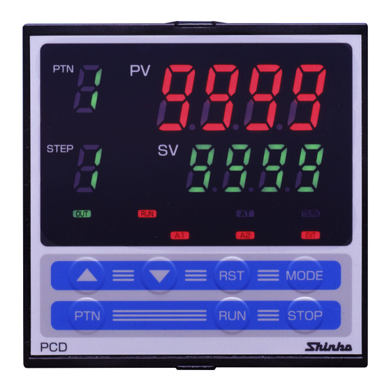
2 Name and functions of the sections 2.1 Name and Displays (11) (10) (Fig. 2.1-1) (1) PV display (Red) Indicates the Process variable (PV). When the setting mode is indicated, the setting item is indicated. (2) SV display (Green) Indicates the Set value (SV). When the setting mode is indicated, the set value is indicated. -
Page 8: Keys
2.2 Keys (18) (17) (12) (16) (13) (15) (14) (Fig. 2.2-1) (12) (Increase key) : Increases the numeric value on the SV display or switches to the next item. (13) (Decrease key) : Decreases the numeric value on the SV display or switches to the next item. -
Page 9: External Dimensions And Panel Cutout
3.3 Mounting Mounting panel thickness is 1 to 15mm. Insert the PCD-33A from the front of the control panel. Slot the mounting bracket to the holes at the top and bottom of the case, and screw in place. -
Page 10: Wiring
• Use the solderless terminal with an insulation sleeve in which the M3 screw fits when wiring the PCD-33A terminals. • The terminal block of the PCD-33A is designed to be wired from the left side. The lead wire must be inserted from the left side of the terminal, and fastened with the terminal screw. -
Page 11: Terminal Arrangement
Communication (RS-485) C5 4.1 Terminal arrangement or Set value digital transmission SVTC YA(-) Ground Power supply 100 to 240V AC Event output 24V DC or 24V AC (EVT) YB(+) Control output Relay contact Non-contact External operation voltage input DC current Alarm 1 (A1) Insulated power Alarm 2 (A2) -
Page 12: Wiring Examples
Open to Closed. Closed to Open. (Fig.4.1-4) 4.2 Wiring examples Caution PCD-33A-R/M For a 24V AC/DC power source, 3-phase do not confuse polarity when using direct current (DC). 100 to 240V AC or 24V AC/DC... - Page 13 For the relay contact output type (PCD-33A-R/M), it is recommended that a surge absorber be installed between the electromagnetic switch coils to prevent the unit from harmful effects of unexpected level noise. PCD-33A-S/M Single phase 100 to 240V AC or 24V AC/DC...
-
Page 14: Setup
Alarm type, Control action, etc. according to the users’ conditions. If the users’ specification is the same as the default value of the PCD-33A, it is not necessary to set up the controller. Proceed to Chapter “6. Operation” (p.21) Set up the controller after connecting terminals 2 and 3 for the power supply to this instrument, referring to “4. -
Page 15: Basic Operation For Setup
(19) Alarm 2 (A2) action delayed timer setting 0 seconds Sets Alarm 2 (A2) action delayed timer. (20) Event output function selection Time signal Selects an Event output type. output (21) Pattern end output time setting 0sec(Continuous Sets pattern end output time. output) (22) Direct/Reverse action selection... -
Page 16: Setting Items In Auxiliary Function Setting Mode
5.3 Setting items in Auxiliary function setting mode 2 : Input type selection Selects a sensor type and temperature unit. Set the same sensor type as the users’. Selecting item: Refer to (Table 5.3-1) below. Default value: (K, -200 to 1370 ) (Table 5.3-1) Input types... - Page 17 • Selecting item: No decimal point 1 digit after the decimal point 2-digit after the decimal point 3-digit after the decimal point • Default value: (No decimal point) : PV filter time constant setting Sets the PV filter time constant. This reduces input fluctuation caused by noise.
- Page 18 (12) Alarm 1 (A1) type selection Selects Alarm 1 (A1) type, referring to 8.5 Alarm 1 (A1) action (pages 48, 49). • Selecting item: No alarm action High limit alarm Low limit alarm High and Low limits alarm High and Low limit range alarm Process High alarm Process Low alarm High limit alarm with standby...
- Page 19 (20) Event output function selection Selects an Event output type from Time signal output, Pattern end output and Run output. When Event output is turned ON, EVT indicator is turned on, and terminals 12 and 13 are used for the Event output. •...
- Page 20 [Run output] (Fig. 5.3-3) This is outputted during the program control. Temperature Step 1 Step 2 Step 3 Time Program control end Run output OFF Run output ON Run output OFF (Fig. 5.3-3) (21) Pattern end output time setting Sets pattern end output time after pattern end output has been selected during Event output function selection.
-
Page 21: Operation
6. Operation Key operation for setup : Selects a program pattern number. : Increases or decreases the numeric value or switches the selecting item. key : Registers the set value (numeric value) or selected item. By pressing the key, the controller reverts to the program standby mode or program control run mode. -
Page 22: Operation Flowchart
6.1 Operation flowchart Power ON Automatically reverts to the Program standby (*2) (*1) mode after data is cleared. Program standby mode Data clearing Each time the key is Program control run mode pressed, the pattern number STEP on the PTN display changes. (Approx. - Page 23 The setting items with dotted lines are optional and BY pressing the key, the they appear only when the options are applied. controller reverts to (*1) or (*2) from any mode. (Approx. 3sec) (Approx. 3sec) [Auxiliary function [Auxiliary function setting mode 1] setting mode 2] Set value lock Input type...
-
Page 24: Operation
6.2 Operation (1) Turn the power supply to the controller ON. The sensor input character and temperature unit are indicated on the PV display, and the input range high limit value is indicated on the SV display for approx. 3 seconds after the power is turned ON. -
Page 25: Pattern (Step Sv/Time) Setting Mode
Actual temp. Program pattern 1 is selected. STEP Actual temp. Program pattern 2 is selected. STEP Program pattern 3 is selected. Actual temp. STEP Actual temp. Program pattern 9 is selected. STEP (4) Pattern (step SV/Time) setting mode This mode is available for the currently selected program pattern number. The following is an example of program pattern setting and its procedures. - Page 26 Press the key. Step 1 SV is registered, and STEP Step 1 time setting mode is indicated. Step 1 time setting Set the step time to (1:00) using key. STEP • Setting range: to 00:00 to 99:59 (Hour:Minute or Minute:Second) •...
-
Page 27: Alarm/Time Signal Setting Mode
(5) Alarm/Time signal setting mode Alarm/Time signal setting mode is available for the currently selected program pattern number. During program control run, settings are available only for the running pattern. Note: To go to the Alarm/Time signal setting mode, select an alarm type except for No alarm action from Alarm 1 (A1) and Alarm 2 (A2) type selection in “5. -
Page 28: Pid Parameter Setting Mode
Pattern 1 Time signal output OFF time setting Sets Time signal output OFF time after the STEP program control run. Available only when Time signal output is selected during Event output function selection. • Setting range: 00:00 to 99.59 (Hour:Minute or Minute:Second) •... -
Page 29: Wait Parameter Setting Mode
Integral time setting Sets the integral time. STEP Off when set to 0 Not available for ON/OFF action • Setting range: 0 to 1000 seconds • Default value: 200 seconds Derivative time setting Sets the derivative time. STEP Off when set to 0 Not available for ON/OFF action •... - Page 30 [Program standby mode or program control run mode] Press the key for 3 seconds while Actual temp. holding down the key. STEP Wait parameter setting mode is selected, and (3sec) Wait value setting item is indicated. [Wait parameter setting mode] Wait value setting Sets Pattern 1 Wait value.
-
Page 31: Auxiliary Function Setting Mode 1
[Program standby mode or program control run mode] Actual temp. STEP Auxiliary function setting mode 1 The settings in Auxiliary function setting mode 1 are applied to all program pattern numbers. [Program standby mode or program control run mode] Press the key for 3 seconds while Actual temp. - Page 32 • Default value: Shinko protocol Instrument number setting Selects the instrument number. STEP Set the instrument number of the PCD-33A individually when communicating by connecting plural PCD-33A units. Available only when C5/SVTC (option) is applied. • Setting range: 0 to 95 •...
-
Page 33: Auxiliary Function Setting Mode
[Program standby mode or program control run mode] Actual temp. STEP (9) Auxiliary function setting mode 2 The settings in Auxiliary function setting mode 2 have already been completed in Chapter “5. Setup” (p.14). (10) Data clearing function This function returns all set values to the default values (See pages 58, 59). This function can only be used during program standby mode. -
Page 34: Running
7. Running [Before running] Before running the controller, check the mounting and wiring carefully, referring to “3. Mounting to the control panel” (p.8) and “4. Wiring” (p.10). Check that settings are applicable for the users’ conditions, referring to “5. Setup” (p.14). 7.1 How to set the program Set the following items, referring to “6. - Page 35 PV start: When the program control starts, SV and step time are advanced to the PV, then the program control is performed. However, if the value set during the [Step SV setting when control starts] and the step SV are equal, or if the value set during the [Step SV setting when control starts] is higher than PV, PV start is cancelled, and SV start is adopted.
- Page 36 [Action after power is restored] (1) If power failure occurs during the program control run, the control resumes from the point at which power failure occurred. (2) If power failure occurs during program standby mode, the control resumes from the program standby mode. [Indication during Wait action] PTN display : Selected program pattern number...
- Page 37 When the program pattern is falling [The Wait function is cancelled at (SV + Wait temperature)] Temperature Wait cancellation range The control proceeds to the next The step at which step at PV the Wait funtion was set SV=500 Wait temperature 10 C Time : Program pattern (Fig.
- Page 38 [Indication during Time signal action] If Time signal output is selected during the [Event output function selection], Event output is turned on during time signal output ON time. Time signal output ON time follows time signal output OFF time after the program control starts.
-
Page 39: Stopping Program Control
The following shows the indication during Run output. PTN display : Selected program pattern number Actual temp. PV display : Current actual temperature STEP Step SV STEP display : Step number of the program control which is running SV display : Current step temperature RUN indicator : L it EVT indicator... -
Page 40: Switching To Fixed Value Control (Hold Function)
Temperature C Step 1 Step 2 Step 3 1000 Advance Time 01.00 (1 hour) 01.00 (1 hour) 00.40(40min.) Time signal Program control run Turned ON after 1 hour Turned OFF after 1 hour and 20 minutes and 50 minutes Setting Time signal OFF time: 1 hour and 20 minutes, Time signal ON time: 30 minutes (Fig. -
Page 41: Correcting Pv (Sensor Correction Function)
[Time signal action during fixed value control] During the fixed value control, step time of the step at which the Hold function was set is regarded as (00:00). Time signal time measurement is carried out ignoring this step. Step number Temperature C Advance SV=500... -
Page 42: Pid Auto-Tuning
[Auxiliary function setting mode 1] Press the key 3 times. Sensor correction setting item is indicated. STEP Selected value (Press 3 times) Set the sensor correction value with the key. STEP Setting range: -100.0 to 100.0 For DC input, -1000 to 1000 (The placement of the decimal point follows the selection) Press the key. - Page 43 [PID auto-tuning performing conditions] (A) When processing temperature is lower than [SV –20 (40 )] The AT process will fluctuate at the temperature 20 (40 ) lower than the SV. Temperature 20 (40 ) lower than the SV (1) Calculating PID constant (2) PID constant calculated...
- Page 44 [If P, I, D, ARW values cannot be changed] • If PID auto-tuning does not finish in 4 hours after it starts, it will be cancelled automatically, and P, I, D, ARW values return to the value set before the auto-tuning was performed.
-
Page 45: Control And Alarm Action
[How to cancel PID auto-tuning] Available only during PID auto-tuning Perform [PID auto-tuning Perform] Press the key while holding down Actual temp. key. STEP Step SV PID parameter setting mode is selected and AT Perform/Cancel item is indicated. [PID parameter setting mode] AT Perform/Cancel selection Press the key. -
Page 46: Derivative Time (D)
(3) Derivative time (D) Derivative action is used to restore the change in the processing temperature according to the rate of change. It reduces the amplitude of overshoot and undershoot width. If the derivative time is shortened, the restoring value becomes smaller, and if the derivative time is extended longer, an excessive returning phenomenon may occur and the control system may oscillate. -
Page 47: On/Off Action
8.3 ON/OFF action Heating (reverse) action Cooling (direct) action Hysteresis Hysteresis Control action SV setting SV setting Relay contact output Non-contact 12V DC 0V DC 0V DC 12V DC voltage output DC current 20mA DC 20mA DC 4mA DC 4mA DC output Indicator (OUT1) Green... -
Page 48: Alarm 1 (A1) And Alarm 2 (A2) Action
8.5 Alarm 1 (A1), Alarm 2 (A2) action High limit alarm Low limit alarm A1 hysteresis A1 hysteresis Alarm action + A1 + A1 set point set point set point set point setting setting + side + side Alarm output side side High/Low limits alarm... -
Page 49: Other Functions
High/Low limits alarm with standby A1 hysteresis Alarm action SV setting set point set point Alarm output : A1 output terminals 7 and 8 are connected (ON). A1 output terminals 7 and 8 are connected (ON) or disconnected (OFF). A1 output terminals 7 and 8 are disconnected (OFF). Standby functions. - Page 50 Automatic cold junction temperature compensation (Only thermocouple input type) This detects the temperature at the connecting terminal between the thermocouple and the instrument, and always maintains the same status as when the reference junction is located at 0 (32 ). Burnout When the thermocouple or RTD input is burnt out, PV display flashes “...
-
Page 51: Specifications
10. Specifications 10.1 Standard specifications Model : Programmable controller Name : PCD-33A Mounting : Flush Setting : Input system using membrane sheet key Display PV display : Red LED display 4 digits, character size, 18(H) x 8(W)mm SV display : Green LED display 4 digits, character size, 12.6(H) x6(W)mm PTN display : Green LED display 1 digit, character size, 12.6(H) x 6(W) mm... - Page 52 Setting resolution Temperature: Refer to Section “1.2 Rated input” (p. 6). Time : 1 minute or 1 second Status after power is restored: The control resumes from the point at which power failure occurred. (Progressing time error after power is restored: Max. 1 minute) Controlling action •...
- Page 53 50/60Hz, or 24V AC/DC 50/60Hz For the supply voltage, 100 to 240V AC is standard. For 24V AC/DC, “1” is entered after the model name PCD-33A-x/M. Allowable voltage fluctuation: 100 to 240V AC: 85 to 264V AC 24V AC/DC : 20 to 28V AC/DC...
-
Page 54: Optional Specifications
Circuit insulation configuration Communication Power Event output supply Insulated Control output (OUT) External operation Alarm 1 (A1) output Alarm 2 (A2) output or Input Insulated power output (P24) When the control output is non-contact voltage or DC current, A is not insulated from B, and A is not insulated from C. Insulation resistance or more, at 500V DC for other combinations except those mentioned above Dielectric strength... -
Page 55: Troubleshooting
If SVTC option is added, external operation function cannot be used. If Set value digital transmission is selected during Communication protocol selection, step SV of the PCD-33A can be transmitted digitally to a maximum of 31 units of Shinko controllers with communication function (C5 option). - Page 56 <Indication> Problem Presumed cause and solution • Thermocouple or RTD is burnt out. ] is flashing [Thermocouple] on the PV display. If the input terminal of the instrument is shorted, and if a value around room temperature indicated, instrument is likely to be operating normally, however, the sensor may be burnt out.
- Page 57 The setting indication • SV high limit or low limit in Auxiliary function setting does not change in mode 1 may be set at the point where the value does the input range even not change. if the keys are Set it to a suitable value ( , or ) while in...
-
Page 58: Character Table
12. Character table Photocopiable material <Set value/Time setting mode> Setting item Default value Data Step No. PV display Step 1 SV Step 1 time 00.00 (H:M) Step 2 SV Step 2 time 00.00 (H:M) Step 3 SV Step 3 time 00.00 (H:M) Step 4 SV Step 4 time... - Page 59 Step No. PV display Set value lock Unlock SV high limit 1370 SV low limit -200 Sensor correction Communication protocol Shinko protocol Instrument number Communication speed 9600bps Parity Even Stop bit <Auxiliary function setting mode 2> Setting item Default value Data Step No.
-
Page 60: How To Make The Program Pattern Table
13. How to make the program pattern table Before setting the program, make a program pattern and data table. Copy the program pattern table and follow the procedure mentioned below. (1) Write down the program pattern number. (2) From Step 1, write down step SV and time of each step in sequence. (3) Write down Alarm 1 (A1) and Alarm 2 (A2) action points and Time signal output time. - Page 61 This page is deliberately left blank.
- Page 62 Program pattern (Pattern number) Step number (Set value) Step temperature ( Step time (Hour:Minute) Wait function Used/Not used Wait value P (Proportional band) I (Integral time) D (derivative time) Anti-reset windup Proportional cycle Time signal output...
- Page 64 • Serial number ----------------- No. xxxxxx In addition to the above, please let us know the details of the malfunction, if any, and the operating conditions. SHINKO TECHNOS CO., LTD. OVERSEAS DIVISION Reg. Office 2-5-1, Senbahigashi, Minoo, Osaka, Japan http://www.shinko-technos.co.jp...
Need help?
Do you have a question about the PCD-33A and is the answer not in the manual?
Questions and answers