Shinko DCL-33A Series Instruction Manual
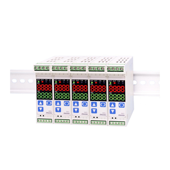
Din rail mounting type digital indicating limit controller
Hide thumbs
Also See for DCL-33A Series:
- Instruction manual (56 pages) ,
- Communication instruction manual (40 pages) ,
- Instructions manual (21 pages)
Table of Contents
Advertisement
Quick Links
INSTRUCTION MANUAL
DIN rail mounting type digital indicating limit controller
To prevent accidents arising from the misuse of this limit controller, please ensure the operator receives this
manual .
Safety precautions
The safety precautions are classified into categories: "Warning" and "Caution". Depending on circumstances,
procedures indicated by
usage.
Procedures which may lead to dangerous conditions and cause death or serious
Warning
injury, if not carried out properly.
Procedures which may lead to dangerous conditions and cause superficial to medium
Caution
injury or physical damage or may degrade or damage the product, if not carried out
properly.
Warning
• To prevent an electric shock or fire, only Shinko or other qualified service personnel may handle the inner
assembly.
• To prevent an electric shock, fire or damage to the instrument, parts replacement may only be undertaken
by our or other qualified service personnel.
Safety precautions
• To ensure safe and correct use, thoroughly read and understand this manual before using this instrument.
• This instrument is intended to be used for industrial machinery, machine tools and measuring equipment. Verify
correct usage after consulting purpose of use with our agency or main office. (Never use this instrument for
medical purposes with which human lives are involved.)
• External protection devices such as protection equipment against excessive temperature rise, etc. must be
installed, as malfunction of this product could result in serious damage to the system or injury to personnel.
Also proper periodic maintenance is required.
• This instrument must be used under the conditions and environment described in this manual. We do not accept
liability for any injury, loss of life or damage occurring due to the instrument being used under conditions not
otherwise stated in this manual.
Caution with respect to Export Trade Control Ordinance
To avoid this instrument from being used as a component in, or as being utilized in the manufacture of weapons of
mass destruction (i.e. military applications, military equipment, etc.), please investigate the end users and the final
use of this instrument. In the case of resale, ensure that this instrument is not illegally exported.
Caution
• This instrument should be used according to the specifications described in the manual.
If it is not used according to the specifications, it may malfunction or cause fire.
• Be sure to follow the warnings, cautions and notices. Not doing so could cause serious injury or malfunction.
• Specifications of the DCL-33A and the contents of this instruction manual are subject to change without notice.
• This instrument is designed to be installed on a DIN rail. If it is not, measures must be taken to ensure that
the operator cannot touch power terminals or other high voltage sections.
• Be sure to turn the power supply to the instrument OFF before cleaning this instrument.
• Use a soft, dry cloth when cleaning the instrument.
(Alcohol based substances may tarnish or deface the unit.)
• As the display section is vulnerable, do not strike or scratch it with a hard object.
• Any unauthorized transfer or copying of this document, in part or in whole, is prohibited.
• Shinko Technos CO., LTD. is not liable for any damages or secondary damages incurred as a result of using
this product, including any indirect damages.
(Be sure to read these precautions before using our products.)
Caution may cause serious results, so be sure to follow the directions for
DCL-33A-R/M T6119
1
DCL33T6119E1 2007.03
Advertisement
Table of Contents

Related Manuals for Shinko DCL-33A Series


Summary of Contents for Shinko DCL-33A Series
- Page 1 • Any unauthorized transfer or copying of this document, in part or in whole, is prohibited. • Shinko Technos CO., LTD. is not liable for any damages or secondary damages incurred as a result of using this product, including any indirect damages.
-
Page 2: Name And Functions Of The Sections
1. Model 1.1 Model D C L – 3 3 A – R / M T6119, W22.5 x H75 x D100mm Alarm Alarm output ( Alarm type can be selected by keypad) *1 Control output Limit control output (Relay contact, 1a) Input Multi-range *2 Control action... -
Page 3: Mounting To The Control Panel
3. Mounting to the control panel 3.1 Site selection Caution • Use within the following temperature and humidity ranges. Temperature: 0 to 50 (32 to 122 ), Humidity: 35 to 85%RH (No condensation, no icing) • When this unit is installed on a DIN rail within a control panel, the ambient temperature of this unit must be kept to under 50 . - Page 4 • Recommended fastening plate Manufacturer Model Omron corporation End plate PFP-M IDEC corporation Fastening plate BNL6 Matsushita electric works, LTD. Fastening plate ATA4806 Mounting to the DIN rail (Fig. 3.3-1) First, hook of the DCL-33A on the upper side of the DIN rail. Second, making part of the DCL-33A as a support, fit the lower part of the DCL-33A to the DIN...
- Page 5 4. Wiring Warning Turn the power supply to the instrument OFF before wiring or checking it. Working or touching the terminal with the power switched ON may result in severe injury or death due to Electric Shock. Caution • Do not leave bits of wire in the DCL-33A when wiring, because they could cause a fire or malfunction. •...
- Page 6 5. Settings 5.1 Operation flowchart Outline of operation procedure Set Input type, Alarm (type, value, etc.) and SV (desired value), following the procedures below. Setting item numbers (1) to (7) are indicated on the flowchart. [Step 1 Operation before run] Turn the load circuit power OFF, and turn the power supply to the DCL-33A ON. Set Input type, Alarm type, etc.
- Page 7 Input type (character indication) and range Alarm type -200 to 1370 -320 to 2500 (High limit alarm) : The alarm action is deviation setting from the SV. The alarm is -199.9 to 400.0 -199.9 to 750.0 activated if the PV (process variable) reaches the high limit set value. -200 to 1000 -320 to 1800 (Low limit alarm)
- Page 8 After the power is turned on, the sensor input characters and temperature unit are indicated on the PV display, and the input range high limit value is indicated on the SV display for approximately 3 seconds. See (Table 5.1-1). (If any other value is set during the scaling high limit setting, the set value is indicated on the SV display) During this time, all outputs and the LED indicators are in OFF status.
- Page 9 5.2 Display mode Selects an item to be indicated on the PV and SV display. Use the key for switching the indication. When power is turned on, the PV/SV display is indicated. Character Name, Function, Setting range Default value PV/SV display The PV display indicates PV (process variable), and the SV display indicates SV (desired value).
- Page 10 : 19200bps Parity selection Even parity • Selects the parity. • Not available if the C5 option is not added or if Shinko protocol is selected during the Communication protocol selection. • Selection item: : No parity : Even parity...
- Page 11 5.5 Setup mode Sets input type, Alarm type, High/Low limit control action, etc. In the PV/SV display mode, press the key for approx. 3 seconds while holding down the keys to proceed to the Setup mode. To set values, use the key.
- Page 12 No alarm action Alarm type selection • Selects an alarm action type. • Selection item: : No alarm action : High limit alarm : Low limit alarm : High/Low limits alarm : High/Low limit range alarm : Process high alarm : Process low alarm : High limit alarm with standby : Low limit alarm with standby...
- Page 13 Energized/Deenergized When Alarm Energized is selected, the Alarm output (between terminals 8-9) is conducted (ON) while the Alarm output indicator is lit. The Alarm output is not conducted (OFF) while the Alarm output indicator is not lit. When Alarm Deenergized is selected, the Alarm output (between terminals 8-9) is not conducted (OFF) while the Alarm output indicator is lit.
-
Page 14: Action Explanation
7. Action explanation 7.1 High limit control action (Fig. 7.1-1) Auto start will be used for purposes of explanation of the High limit control action. (Refer to Section 7.3) key or External reset input Hysteresis Flashing EXCEEDED indication (PV display) Unlit Unlit RESET indicator... - Page 15 7.2 Low limit control action (Fig. 7.2-1) Auto start will be used for purposes of explanation of the Low limit control action. (Refer to Section 7.3) key or External reset input Hysteresis EXCEEDED indication Flashing (PV display) Unlit Unlit RESET indicator Limit control output 3-4 POWER OFF POWER ON...
-
Page 16: Specifications
7.4 Alarm action High limit alarm Low limit alarm High/Low limits alarm Alarm hysteresis Alarm hysteresis Alarm hysteresis Alarm action Alarm value + Alarm value Alarm value + Alarm value Alarm value Alarm value + side + side Alarm output - side - side High/Low limit range alarm... - Page 17 Limit control output Relay contact : 1a, Control capacity 3A 250V AC (resistive load) 1A 250V AC (inductive load cosø=0.4) Electrical life, 100,000 times Alarm output Action : ON/OFF action Hysteresis : 0.1 to 100.0 ( ), DC input: 1 to 1000 (The placement of the decimal point follows the selection) Output : Open collector...
- Page 18 : 2400/4800/9600/19200bps (Selectable by keypad) Parity : Even/Odd/No parity (Selectable by keypad) Stop bit : 1 or 2 (Selectable by keypad) Communication protocol : Shinko protocol/Modbus RTU/Modbus ASCII (Selectable by keypad) Communication protocol Shinko protocol Modbus ASCII Modbus RTU Data format...
-
Page 19: Troubleshooting
External reset input Open : Reset OFF External reset input Closed : Reset ON Circuit current when closed: 1mA If DI option is added, UL will not be approved. 9. Troubleshooting If any malfunctions occur, refer to the following items after checking the power supply to the controller. 9.1 Indication Presumed cause and solution Problem... - Page 20 • Check whether the wiring of sensor or control output terminals is correct. • If you have any inquiries, please consult our agency or the shop where you purchased the unit. SHINKO TECHNOS CO.,LTD. OVERSEAS DIVISION Reg. Office 2-5-1, Senbahigashi, Minoo, Osaka, Japan http://www.shinko-technos.co.jp...
Need help?
Do you have a question about the DCL-33A Series and is the answer not in the manual?
Questions and answers