Table of Contents
Advertisement
Quick Links
Advertisement
Table of Contents

Related Manuals for Shinko PCA1


Summary of Contents for Shinko PCA1
- Page 1 PROGRAMMABLE CONTROLLER PCA1 INSTRUCTION MANUAL...
- Page 2 • Any unauthorized transfer or copying of this document, in part or in whole, is prohibited. • Shinko Technos Co., Ltd. is not liable for any damage or secondary damage(s) incurred as a result of using this product, including any indirect damage.
- Page 3 Warning • To prevent an electrical shock or fire, only Shinko or other qualified service personnel may handle the inner assembly. • To prevent an electrical shock, fire or damage to the instrument, parts replacement may only be undertaken by Shinko or other qualified service personnel.
- Page 4 2. Wiring Precautions Caution • Do not leave wire remnants in the instrument, as they could cause a fire or malfunction. • Use the solderless terminal with an insulation sleeve in which the M3 screw fits when wiring the instrument. •...
-
Page 5: Table Of Contents
Contents 1. Model ..............................1.1 Model............................... 1.2 How to Read the Model Label......................2. Name and Functions of Controller ..................... 3. Mounting to the Control Panel......................3.1 External Dimensions (Scale: mm)....................3.2 Panel Cutout (Scale: mm) ....................... 3.3 Mounting to, and Removal from, the Control Panel................ 3.3.1 Mounting the Unit ........................ - Page 6 12.18 Other Parameters Setting Group ....................169 12.19 Auto/Manual Control Switch Group..................... 172 13. Making Program Pattern Table and Data Table................173 13.1 Making Program Pattern Table...................... 173 13.2 Making Data Table......................... 175 PCA1 Key Operation Flowchart......................179 - 6 -...
-
Page 7: Model
1. Model 1.1 Model PCA1 Relay contact output Control output Non-contact voltage output OUT1 Direct current output 100 to 240 V AC Power supply voltage 24 V AC/DC Input Multi-range (*1) Option 1 not needed. Serial communication RS-232C Serial communication RS-485... -
Page 8: How To Read The Model Label
Power consumption 14 VA Serial number No. 165F05000 ⑦ RoHS directive RoHS directive compliant ⑧ UL recognized factory ID SF: Fukuoka factory ⑨ Manufacturer SHINKO TECHNOS CO., LTD. ⑩ Terminal arrangement diagram differs depending on the model. - 8 -... -
Page 9: Name And Functions Of Controller
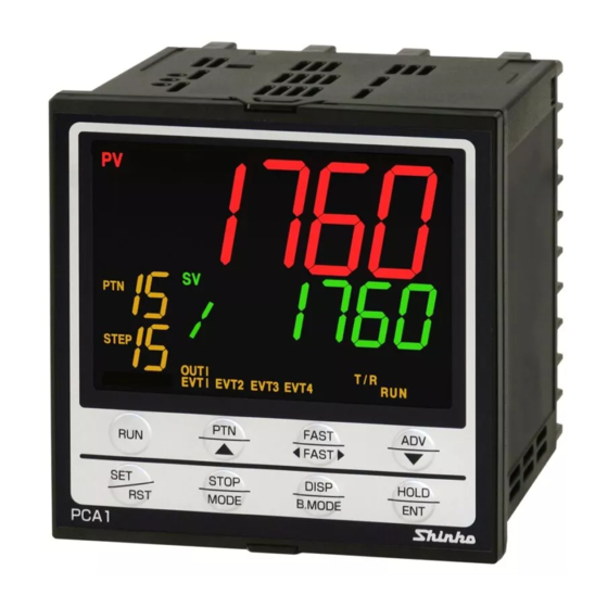
2. Name and Functions of Controller ① ② ③ ⑤ ④ ⑥ ⑦ ⑩ ⑧ ⑪ ⑨ ⑫ ⑯ ⑰ ⑬ ⑭ ⑱ ⑮ ⑲ ⑳ (Fig. 2-1) - 9 -... - Page 10 Action Indicators, Display Name Description PV indicator Backlight: Red/Green/Orange ① Lit when PV is indicated in RUN mode. PV Display Backlight: Red/Green/Orange ② Indicates PV in RUN mode. Indicates setting characters in setting mode. SV indicator Backlight: Green ③ Lit when SV is indicated on the SV/MV/TIME Display. Retains indicator status at power OFF.
- Page 11 Action Indicator (Backlight: Orange) Name Description Lit when control output OUT1 is ON. OUT1 ⑪ For direct current output type, flashes corresponding to the MV in 125 ms cycles. Lit when control output OUT2 (DR, DS or DA option) is ON. OUT2 For direct current output type (DA option), flashes corresponding to the MV in 125 ms cycles.
-
Page 12: Mounting To The Control Panel
3. Mounting to the Control Panel 3.1 External Dimensions (Scale: mm) Terminal cover Gasket Screw type mounting bracket (sold separately) 98.5 11.5 □96 (when terminal cover is used) 104.5 (Fig. 3.1-1) 3.2 Panel Cutout (Scale: mm) Caution If horizontal close mounting is used for the controller, IP66 specification (Drip-proof/Dust-proof) may be compromised, and all warranties will be invalidated. -
Page 13: Mounting To, And Removal From, The Control Panel
3.3 Mounting to, and Removal from, the Control Panel Caution As the case of the PCA1 is made of resin, do not use excessive force while tightening screws, or the mounting brackets or case could be damaged. The torque should be 0.12 N•m. -
Page 14: Wiring
4. Wiring Warning Turn the power supply to the instrument off before wiring or checking. Working on or touching the terminal with the power switched on may result in severe injury or death due to electrical shock. Caution • Do not leave wire remnants in the instrument, as they could cause a fire or malfunction. •... -
Page 15: Terminal Arrangement
4.1 Terminal Arrangement (Fig. 4.1-1) Terminal Code Description Grounding Power supply 100 to 240 V AC or 24 V AC/DC For a 24 V AC/DC, ensure polarity is correct when using direct current (DC). Control output OUT1 Control output OUT2 (DR, DS or DA option) Event output EV1 Event output EV2 Event output EV3... -
Page 16: Lead Wire Solderless Terminal
4.2 Lead Wire Solderless Terminal Use a solderless terminal with an insulation sleeve in which an M3 screw fits as shown below. 0.63 N•m of torque is recommended. Solderless Tightening Manufacturer Model Terminal Torque Nichifu Terminal Industries Co., Ltd. TMEV1.25Y-3 Y-type Japan Solderless Terminal MFG Co., Ltd. -
Page 17: Input
Load resistance: Max. 600 Non-contact voltage, Relay contact Direct current Number of Shinko SSR units when connected in parallel (for Non-contact voltage output): • SA-400 series: 5 units • SA-500 series: 2 units 4.3.4 Input Input wirings are shown below. -
Page 18: Event Output Ev1, Ev2, Ev3 And Ev4
4.3.5 Event Output EV1, EV2, EV3 and EV4 Specifications of Event output EV1, EV2, EV3 and EV4 are shown below. Relay contact Control capacity: 3 A 250 V AC (resistive load) 1 A 250 V AC (inductive load cos =0.4) Electrical life: 100,000 cycles Event output EV3 Event output EV1... -
Page 19: External Operation Input
• 4 points of Event input DI1 to DI4 [ : ON (Closed) status] PTN Display 10 11 12 13 14 15 * This pattern number is selected via the keypad. • 2 points of Event input DI1 and DI2 [ : ON (Closed) status] PTN Display * This pattern number is selected via the keypad. -
Page 20: Serial Communication
When the C or C5 option is ordered, Serial communication is available. C option C5 option (1) Serial Communication Wiring example when using USB communication cable CMC-001-1 (sold separately) PCA1 USB communication cable CMC-001-1 (sold separately) YA(-) ⑬ YA(-) YB(+) ⑭... - Page 21 Shinko indicating controllers with communication function (C5 option). Update cycle: 250 ms Connection Connect YA (-) to YA (-), YB (+) to YB (+), SG to SG terminal (of PCA1 and indicating controllers with communication function) respectively. A maximum of 31 units can be connected.
-
Page 22: Transmission Output
Shield wire Connect only one end of the shield to the FG terminal to avoid a ground loop. If both ends of the shield wire are connected to the FG terminal, the circuit will be closed, resulting in a ground loop. This may cause noise. -
Page 23: Time Signal Output
4.3.10 Time Signal Output If the TS option is ordered, Time signal output is available. Specifications of Time signal output are shown below. Number of circuits Open collector Capacity: 24 V DC Max. 50 mA For the Time signal output, a maximum of 8 points (Time signal output TS1 to TS8) can be selected for each step. -
Page 24: Outline Of Key Operation And Explanation Of Groups
5. Outline of Key Operation and Explanation of Groups 5.1 Outline of Key Operation Power ON (3 sec) Data clear RUN mode Program control Program control Stop (in Standby) (1 sec) Group selection mode Pattern setting Setting items in the Setting pattern group number... - Page 25 Explanation of Mode Mode Description The unit enters the RUN mode when power is turned ON. RUN mode Resumes from Program control Stop (in Standby) or Program control RUN, depending on the status at power OFF. Indication differs depending on the status below. Program control PV, SV and PTN indicators light up.
-
Page 26: Block Setting Group
5.1.1 Block Setting Group PID block setting Setting items in the Block setting group group group Time signal block Setting items in the setting group group Wait block setting Setting items in the group group Alarm block setting Setting items in the group (*) group Output block setting... -
Page 27: Engineering Setting Group
5.1.2 Engineering Setting Group Engineering setting Input parameter Setting items in the setting group group group Output parameter Setting items in the setting group group Setting items in the Event output para- meter setting group group SV limit setting Setting items in the group group Transmission output... -
Page 28: Explanation Of Groups
5.2 Explanation of Groups Press the key in RUN mode. The unit moves to Pattern setting group in Group selection mode. Select a group with the key, and press the key. Setting items in the group can be set. If the key is pressed in the Block setting group, the unit enters setting groups such as PID block, Alarm block. - Page 29 Group PV Display Contents Engineering setting Selects the following setting groups: group Input parameter, Output parameter, Event output parameter, SV limit, Transmission output parameter, Communication parameter, Other parameters Input parameter Sets the following items: setting group Input type, Scaling high limit, Scaling low limit, Decimal point place, Sensor correction, PV filter time constant Output parameter Sets the following items:...
-
Page 30: Basic Operating Procedure After Power On And Setting Examples
6. Basic Operating Procedure after Power ON and Setting Examples 6.1 Basic Operating Procedure after Power ON Power ON Initial setting Input parameter (p.34) Output parameter Set Input and Output parameters. (p.35) Event output parameter (p.35) Other parameters Set program control related data. (p.36) Program pattern setting... -
Page 31: Initial Setting, Program Pattern Setting And Block Setting
6.2 Initial Setting, Program Pattern Setting and Block Setting • Example of Initial Setting Setting Group Setting Item Setting Example Input parameter Input type K, -200 to 1370 setting group Scaling high limit 1200 Scaling low limit Output parameter OUT1 proportional cycle 15 seconds setting group Direct/Reverse action... - Page 32 Explanation of the Program Pattern Step 0: After program control starts, control is performed so that SV gradually rises from 0 to 500 for 30 minutes. Step 1: Control is performed to keep the SV at 500 for 1 hour. Step 2: Control is performed so that SV gradually rises from 500 to 1000 for 40 minutes.
- Page 33 Operation method will be described based on the Initial setting, Program pattern setting and Block setting examples. Indication of Setting Details Input type • Upper left: PV Display: Indicates setting item characters. • Lower left: SV/MV/TIME Display: Indicates setting values or selections. •...
- Page 34 Basic Procedure Setting details Power ON Power ON RUN mode RUN mode [Program control Stop (in Standby)] Pattern setting group (4 times) Engineering setting group Input parameter setting Input parameter setting group group Input type K -200 to 1370°C Scaling high limit 1200°C Scaling low limit 0°C...
- Page 35 Output parameter Output parameter setting group setting group OUT1 proportional cycle 15 seconds (Multiple times) Direct/Reverse action Reverse action Output parameter setting group Event output parameter Event output parameter setting group setting group (Twice) Event output EV2 allocation Process high alarm (3 times) EV2 alarm Energized/De-energized Energized...
- Page 36 Other parameters Other parameters setting group setting group (Twice) Program start Auto/Manual Manual start (Twice) Program control start type PV start Power restore action Continues after power is restored Step time unit Hours: Minutes Step time indication Remaining time Step SV indication - 36 -...
- Page 37 SV corresponding to the step time progress (Twice) Step SV Hold function when program ends Not holding (Twice) Engineering setting group (Twice) Pattern setting group Pattern setting group Setting pattern number Step 0 Step SV °C Step 0 Step time 0:30 Step 0 PID block number - 37 -...
- Page 38 Step 0 Wait block number Step 0 Alarm block number Step 0 Output block number Step 1 Step SV 500°C Step 1 Step time 1:00 Step 1 PID block number - 38 -...
- Page 39 Set items up to ‘Step 4 Output block number’ in the same way. Step 4 Output block number Pattern setting group Block setting group PID block setting group PID block setting group At this stage, setting items in the PID block setting group do not need to be set, as PID constants are obtained by performing AT.
- Page 40 600°C Block 1 EV3 alarm value 5°C Block 1 EV4 alarm value 5°C Block 2 EV2 alarm value 1100°C Block 2 EV3 alarm value 10°C Block 2 EV4 alarm value 10°C Alarm block setting group - 40 -...
- Page 41 Output block setting Output block setting group group (Multiple times) Block 1 OUT1 high limit Block 1 OUT1 low limit At this stage, settings are complete. RUN mode RUN mode [Program control Stop (in Standby)] Pattern number to perform Select Pattern 1 with the key.
- Page 42 AT mode Normal mode AT Perform/Cancel AT Perform RUN mode The AT indicator flashes while AT is performing. The AT indicator turns OFF after AT finishes. Perform AT at Steps 2 or 3 for which PID block number 2 is selected in the same way. Program control complete Program control STOP After program control is finished, pattern end...
-
Page 43: Setting Items
7. Setting Items Caution • When connecting USB communication cable (CMB-001) to the console connector, connect the cable after power is turned OFF. • Never turn the power ON or OFF, while USB communication cable (CMB-001) is connected to the console connector. The following groups will be described: Pattern setting group, Block setting group, Repetitions and Pattern link setting group, AT perform group, Engineering setting group, Auto/Manual control switch group... - Page 44 Setting items in the Pattern setting group are shown below. Character, Setting Item, Function, Setting Range Factory Default Setting pattern number • Selects the setting pattern number. • Selection item: 0 to 15 Step 0 step SV • Sets Step 0 step SV. Step SV is the value at the end of the step.
- Page 45 Character, Setting Item, Function, Setting Range Factory Default Step 0 Time signal 4 block number • Selects Time signal 4 block number used for Step 0. Selects any one number from a maximum of 16 Time signal blocks. The same number can be selected as many times as desired. •...
- Page 46 Character, Setting Item, Function, Setting Range Factory Default Step 0 Output block number • Selects an Output block number used for Step 0. • Selection item: 0 to 9 Step 1 step SV • Sets Step 1 step SV. • Setting range: SV low limit to SV high limit Repeat the above settings up to ‘Step 15 Output block number’, in the same way if necessary.
-
Page 47: Block Setting Group
7.2 Block Setting Group In the Block setting group, the following setting groups are included: PID block setting group, Time signal block setting group, Wait block setting group, Alarm block setting group, Output block setting group About settings in each block setting group If program pattern is not set for a step, its block number becomes 0 (zero). -
Page 48: Pid Block Setting Group
7.2.1 PID Block Setting Group In PID block setting group, the following can be set for blocks 0 to 9: OUT1 proportional band, Integral time, Derivative time, ARW and OUT2 proportional band (DR, DS or DA option) Refer to recommended usage of block numbers as follows: Block 0: For Fixed value control Block 1: For low temperature program control Block 2: For medium temperature program control... - Page 49 Character, Setting Item, Function, Setting Range Factory Default Block 1 OUT1 proportional band • Sets Block 1 OUT1 proportional band. When set to 0 or 0.0, OUT1 becomes ON/OFF control. • Setting range: Thermocouple, RTD input without decimal point: 0 to input span Thermocouple, RTD input with decimal point: 0.0 to input span DC voltage, current input: 0.0 to 1000.0% Repeat the above settings up to ‘Block 9 OUT2 proportional band’,...
-
Page 50: Time Signal Block Setting Group
7.2.2 Time Signal Block Setting Group In Time signal block setting group, the following can be set for blocks 0 to 15: Time signal output OFF time, Time signal output ON time • Time signal output function Time signal output OFF time and Time signal output ON time are set within each step time, and outputs them during Program control RUN. - Page 51 ② If ON time is the same value as the step time, the Time signal output will turn OFF for a brief moment while Step numbers change. Therefore, set the Time signal output ON time longer than the step time so that Time signal output may turn ON even when steps changes.
-
Page 52: Wait Block Setting Group
7.2.3 Wait Block Setting Group In Wait block setting group, Wait value can be set for blocks 0 to 9. • Wait function During Program control RUN, the program does not proceed to the next step until the deviation between PV and SV enters SV Wait value at the end of step. When the Wait function is activated, the STEP Display flashes. - Page 53 Setting items in the Wait block setting group are shown below. Character, Setting Item, Function, Setting Range Factory Default Block 0 Wait value • Sets Block 0 Wait value. When set to 0 or 0.0, the Wait function is disabled. •...
-
Page 54: Alarm Block Setting Group
7.2.4 Alarm Block Setting Group In Alarm block setting group, the following can be set for blocks 0 to 9: EV1 alarm value, EV2 alarm value, EV3 alarm value, EV4 alarm value • Alarm output EV1 alarm output actions are shown below. The same applies to EV2 alarm output, EV3 alarm output and EV4 alarm output. - Page 55 • High/Low limit range alarm • High/Low limit range with standby alarm EV1 hysteresis EV1 hysteresis EV1 value EV1 value SV EV1 value SV EV1 value Alarm output is in standby. (Fig. 7.2.4-7) (Fig. 7.2.4-8) • Process high alarm • Process high with standby alarm EV1 hysteresis EV1 hysteresis EV1 value...
- Page 56 Setting items in the Alarm block setting group are shown below. When 001 to 012 (Alarm output) is selected in [Event output EV allocation], the following will appear. Character, Setting Item, Function, Setting Range Factory Default Block 0 EV1 alarm value •...
- Page 57 Character, Setting Item, Function, Setting Range Factory Default Block 0 EV4 alarm value • Sets Block 0 EV4 alarm value. • Setting range: Same as that of Block 0 EV1 alarm value. Available when 001 to 012 (Alarm output) is selected in [Event output EV4 allocation]. Block 1 EV1 alarm value •...
-
Page 58: Output Block Setting Group
7.2.5 Output Block Setting Group In Output block setting group, the following can be set for blocks 0 to 9: OUT1 high limit, OUT1 low limit, OUT2 high limit (DR, DS or DA option), OUT2 low limit (DR, DS or DA option), OUT1 rate-of-change Setting items in the Output block setting group are shown below. - Page 59 100 %/sec 20 %/sec 10 %/sec ON (100%) OFF (0%) 1 sec 5 sec 10 sec (Fig. 7.2.5-2) • Setting range: 0 to 100 %/Second Block 1 OUT1 high limit • Sets Block 1 OUT1 high limit. • Setting range: OUT1 low limit to 100% (For direct current output: OUT1 low limit to 105%) Repeat the above settings up to ‘Block 9 OUT1 rate-of-change’, in the same way if necessary.
-
Page 60: Repetitions And Pattern Link Setting Group
7.3 Repetitions and Pattern Link Setting Group In Repetitions and pattern link setting group, the following can be set: Number of repetitions, Pattern link Pattern numbers 0 to 15 can be linked to the next pattern. Only pattern numbers in numerical order can be linked. - Page 61 Character, Setting Item, Function, Setting Range Factory Default Repetitions for Pattern 1 • Sets the number of repetitions of Pattern 1. • Setting range: 0 to 9999 times Repeat the above settings up to ‘Pattern link between pattern 15 and pattern 0’, in the same way if necessary.
-
Page 62: At Perform Group
7.4 AT Perform Group In AT Perform group, the following can be set: AT mode, AT Perform/Cancel, AT bias • To enter AT Perform group Press the key once in RUN mode, and press the key 3 times. The PV Display indicates ,, and the unit enters the AT Perform group. - Page 63 Character, Setting Item, Function, Setting Range Factory Default AT bias • Sets bias value for the AT. (See p.117) AT point is automatically determined by the deviation between PV and SV. AT bias setting is available for Fixed value control. •...
-
Page 64: Engineering Setting Group
7.5 Engineering Setting Group In Engineering setting group, the following setting groups are included: Input parameter setting group, Output parameter setting group, Event output parameter setting group, SV limit setting group, Transmission output parameter setting group, Communication parameter setting group, Other parameters setting group •... - Page 65 • Explanation of Setting Item Upper left: PTN Display, PV Display The PTN Display is unlit, and the PV Display indicates setting item characters. Lower left: STEP Display, SV/MV/TIME Display The STEP Display is unlit, and the SV/MV/TIME Display indicates factory default. Right side: Indicates the setting item, explanation of its function, and setting range.
-
Page 66: Input Parameter Setting Group
7.5.1 Input Parameter Setting Group In Input parameter setting group, the following can be set: Input type, Scaling high limit, Scaling low limit, Sensor correction, PV filter time constant, etc. Setting items in the Input parameter setting group are shown below. Character, Setting Item, Function, Setting Range Factory Default... - Page 67 Character, Setting Item, Function, Setting Range Factory Default : Pt100 -148.0 to 212.0 : Pt100 -148.0 to 932.0 : 4 to 20 mA DC -2000 to 10000 : 0 to 20 mA DC -2000 to 10000 : 0 to 10 mV DC -2000 to 10000 : -10 to 10 mV DC -2000 to 10000 : 0 to 50 mV DC -2000 to 10000 : 0 to 100 mV DC -2000 to 10000...
- Page 68 Character, Setting Item, Function, Setting Range Factory Default PV filter time constant • Sets PV filter time constant. If the value is set too high, it affects control results due to the delay of response. [PV filter time constant] This is a filter function on the software, which has the same effect as a CR filter.
-
Page 69: Output Parameter Setting Group
7.5.2 Output Parameter Setting Group In Output parameter setting group, the following can be set: OUT1 proportional cycle, OUT1 ON/OFF hysteresis, OUT2 proportional cycle (DR, DS or DA option), OUT2 cooling method (DR, DS or DA option), Direct/Reverse action, etc. Setting items in the Output parameter setting group are shown below. - Page 70 Character, Setting Item, Function, Setting Range Factory Default • Selection item: : Air cooling (Linear characteristics) : Oil cooling (1.5th power of the linear characteristics) : Water cooling (2nd power of the linear characteristics) Available when Heating/Cooling control (DR, DS or DA option) is ordered. OUT2 ON/OFF hysteresis •...
- Page 71 Character, Setting Item, Function, Setting Range Factory Default [Dead band] OUT1 proportional band OUT2 proportional band Dead band OUT1 OUT2 (Fig. 7.5.2-5) • Setting range: Thermocouple, RTD input: -200.0 to 200.0 DC voltage, current input: -2000 to 2000 (The placement of the decimal point follows the selection.) Available when Heating/Cooling control (DR, DS or DA option) is ordered.
-
Page 72: Event Output Parameter Setting Group
7.5.3 Event Output Parameter Setting Group In Event output parameter setting group, the following can be set: Event output EV1 allocation, Event output EV2 allocation, Event output EV3 allocation, Event output EV4 allocation In Event output (EV1 to EV4) allocation, the following can be selected: Alarm output, Pattern end output, Loop break alarm, Output during AT Factory default values for EV1, EV2, EV and EV4: EV1: Pattern end output... - Page 73 • High/Low limit range alarm • High/Low limit range with standby alarm EV1 hysteresis EV1 hysteresis EV1 value EV1 value SV EV1 value SV EV1 value Alarm output is in standby. (Fig. 7.5.3-7) (Fig. 7.5.3-8) • Process high alarm • Process high with standby alarm EV1 hysteresis EV1 hysteresis EV1 value...
- Page 74 Setting items in the Event output parameter setting group are shown below. Character, Setting Item, Function, Setting Range Factory Default Event output EV1 allocation • Selects Event output EV1 from the Event Output Allocation Table below. For Alarm output, the alarm value is set by deviation from the SV (excluding Process alarm), and if the input goes outside the range, the Alarm output is turned ON (turned OFF for High/Low limit range alarm).
- Page 75 Character, Setting Item, Function, Setting Range Factory Default EV1 alarm Energized/De-energized • Selects Energized/De-energized status for EV1 alarm. When Energized is selected, Event output EV1 is conductive (ON) while the EV1 indicator is lit. Event output EV1 is not conductive (OFF) while the EV1 indicator is not lit.
- Page 76 Character, Setting Item, Function, Setting Range Factory Default Loop break alarm span • Sets the action span to assess the Loop break alarm. • Setting range: Thermocouple, RTD input without decimal point: 0 to 150 Thermocouple, RTD input with decimal point: 0.0 to 150.0 DC voltage, current input: 1 to 1500 (The placement of the decimal point follows the selection.)
- Page 77 Character, Setting Item, Function, Setting Range Factory Default EV2 alarm delay time • Sets EV2 alarm action delay time. When setting time has elapsed after PV enters the alarm output range, the alarm is activated. • Setting range: 0 to 10000 seconds Available when 001 to 012 (Alarm output) is selected in [Event output EV2 allocation].
- Page 78 Character, Setting Item, Function, Setting Range Factory Default Loop break alarm span • Sets the action span to assess the Loop break alarm. • Setting range: Thermocouple, RTD input without decimal point: 0 to 150 Thermocouple, RTD input with decimal point: 0.0 to 150.0 DC voltage, current input: 1 to 1500 (The placement of the decimal point follows the selection.)
- Page 79 Character, Setting Item, Function, Setting Range Factory Default EV3 alarm delay time • Sets EV3 alarm action delay time. When setting time has elapsed after PV enters the alarm output range, the alarm is activated. • Setting range: 0 to 10000 seconds Available when 001 to 012 (Alarm output) is selected in [Event output EV3 allocation] EV3 alarm Energized/De-energized •...
- Page 80 Character, Setting Item, Function, Setting Range Factory Default Loop break alarm span • Sets the action span to assess the Loop break alarm. • Setting range: Thermocouple, RTD input without decimal point: 0 to 150 Thermocouple, RTD input with decimal point: 0.0 to 150.0 DC voltage, current input: 1 to 1500 (The placement of the decimal point follows the selection.)
- Page 81 Character, Setting Item, Function, Setting Range Factory Default EV4 alarm delay time • Sets EV4 alarm action delay time. When setting time has elapsed after PV enters the alarm output range, the alarm is activated. • Setting range: 0 to 10000 seconds Available when 001 to 012 (Alarm output) is selected in [Event output EV4 allocation].
- Page 82 Character, Setting Item, Function, Setting Range Factory Default Loop break alarm span • Sets the action span to assess the Loop break alarm. • Setting range: Thermocouple, RTD input without decimal point: 0 to 150 Thermocouple, RTD input with decimal point: 0.0 to 150.0 DC voltage, current input: 1 to 1500 (The placement of the decimal point follows the selection.)
-
Page 83: Sv Limit Setting Group
7.5.4 SV Limit Setting Group In SV limit setting group, the following can be set: SV high limit, SV low limit Setting items in the SV limit setting group are shown below. Character, Setting Item, Function, Setting Range Factory Default SV high limit •... -
Page 84: Transmission Output Parameter Setting Group
7.5.5 Transmission Output Parameter Setting Group In Transmission output parameter setting group, the following can be set: Transmission output type, Transmission output high limit, Transmission output low limit, Setting items in the Transmission output parameter setting group are shown below. Available when Transmission output (TA or TV option) are ordered. -
Page 85: Communication Parameter Setting Group
Character, Setting Item, Function, Setting Range Factory Default Communication protocol • Selects communication protocol. • Selection item: : Shinko protocol : Modbus ASCII : Modbus RTU : Set value (SV) digital transmission Instrument number • Sets the instrument number. The instrument numbers should be set one by one when multiple instruments are connected in Serial communication, otherwise communication is impossible. - Page 86 Character, Setting Item, Function, Setting Range Factory Default Response delay time • Response from the controller can be delayed after receiving command from the host computer. If Response delay time is changed via software communication, the changed delay time will be reflected from that response data. •...
-
Page 87: Other Parameters Setting Group
7.5.7 Other Parameters Setting Group In Other parameters setting group, the following can be set: Set value lock, Program start Auto/Manual, Program control start type, Power restore action, etc. Setting items in the Other parameters setting group are shown below. Character, Setting Item, Function, Setting Range Factory Default... - Page 88 Character, Setting Item, Function, Setting Range Factory Default SV start Time 1:00 Program control starts. Program control starts from the step SV which has been set in [Step SV when program control starts]. (Fig. 7.5.7-2) • Selection item: : PV start Only when program control starts, the step SV is advanced to the PV, then program control starts.
- Page 89 Character, Setting Item, Function, Setting Range Factory Default Step time unit • Selects the Step time unit. • Selection item: : Hours:Minutes : Minutes:Seconds Step time indication • During program control, selects step time indication type when the SV/MV/TIME Display is switched to TIME indication. •...
- Page 90 Character, Setting Item, Function, Setting Range Factory Default Step SV Hold function when program ends • When program control ends, selects either ‘Holding’ or ‘Not holding’ of the Step SV Hold function. If ‘Holding’ is selected, the PTN Display flashes when program control ends, and control performs using the step SV of the last step.
- Page 91 Character, Setting Item, Function, Setting Range Factory Default Time signal output TS5 / Status (STOP) output • Selects either Time signal output or Status (STOP) output for Time signal output TS5. • Selection item: : Time signal output TS5 : Status (STOP) output Available when Time signal output (TS option) is ordered.
- Page 92 Character, Setting Item, Function, Setting Range Factory Default PV color • Selects PV Display color. • Selection item: : Green : Red : Orange : When any alarm (EV1 to EV4) is ON: Green When alarm is OFF: Green When any alarm (EV1 to EV4) is ON: The PV color turns from green to red continuously according to the alarm.
- Page 93 Character, Setting Item, Function, Setting Range Factory Default PV color range • Sets PV color range depending on the user setting. • Setting range: Thermocouple, RTD input: 0.1 to 200.0 DC voltage, current input: 1 to 2000 (The placement of the decimal point follows the selection.) Available when (PV color changes continuously) or...
-
Page 94: Auto/Manual Control Switch Group
7.6 Auto/Manual Control Switch Group In Auto/Manual control switch group, Auto/Manual control can be switched. • To Enter the Auto/Manual control switch group Press the key once in RUN mode, and press the key 5 times. The PV Display indicates , and the unit enters the Auto/Manual control switch group in Group selection mode. -
Page 95: Clearing The Setting Data
7.7 Clearing the Setting Data There are 2 methods in data clearing. • Program Clearing: Program pattern data of the selected step and all the following steps within the program pattern will be removed. • Data Clearing: All setting data – except Input type, OUT1 proportional cycle, OUT2 proportional cycle – will be cleared. Once data is mistakenly cleared, data should be entered again. -
Page 96: Operation
8. Operation 8.1 Performing Program Control 8.1.1 Performing Program Control (1) Before turning the power ON Check Sections “3. Mounting to the Control Panel (pp.12, 13)” and “4. Wiring (p.14 to 23)” before turning the power ON. (2) After turning the power ON Set necessary items after turning the power ON. - Page 97 Event Input DI1 and DI2: Select a performing pattern by closing any one terminal (DI1 or DI2) and the COM terminal. : Close DI1 or DI2 terminal and the COM terminal. (e.g.) To select pattern 3 to perform, close ⑪ & ⑮, and close ⑫ & ⑮. (Table 8.1.1-2) Pattern Terminal No.
- Page 98 [Program control start type] Program control start type can be selected in [Program control start type]. PV start: Only when program control starts, step SV and step time are advanced to the PV, then program control starts. However, if step SV at the time of program control start is higher than the PV (when PV start is initiated), then program control will start from the SV set in [Step SV when program control starts].
- Page 99 [Power Restore Action] If power fails during program control, the controller can be operated depending on the selection in [Power restore action]. Progressing time error when power is restored: 1 minute • Stops after power is restored: After power is restored, stops program control, and returns to Standby mode. •...
- Page 100 [Wait function] While program control is running, the program does not proceed to the next step until the deviation between PV and SV enters SV Wait value at the end of step. The STEP Display flashes while the Wait function is working. Explanation of Wait function •...
-
Page 101: Stopping Program Control
8.1.2 Stopping Program Control To stop program control, press the key, or use External operation input. • Using the Press the key for approximately 1 second during program control. Program control will stop. • Using External operation input Close terminals (STOP) and (COM) of External operation input. -
Page 102: Suspending Program Control (Hold Function)
8.1.3 Suspending Program Control (Hold Function) During program control, progress of current step can be suspended (paused). Pressing the key cancels suspension, and program control resumes. During manual control, suspension cannot be cancelled. To suspend program control, there are 2 methods: Using the key, or using External operation input •... -
Page 103: Advancing Program Step (Advance Function)
8.1.4 Advancing Program Step (Advance Function) Interrupts current step while program control is running, and proceeds to the beginning of the next step. If the Wait function is working, the Wait function is cancelled, and proceeds to the beginning of the next step. -
Page 104: Returning To Previous Program Step (Return-To-Previous Function)
8.1.5 Returning to Previous Program Step (Return-to-Previous Function) Stops the current step in program control, and returns to the previous step. If the elapsed time of the current step is less than 1 minute, the program control returns to the beginning of the previous step. -
Page 105: Speeding Up Program Step Time (Step Time Speed-Up Function)
8.1.6 Speeding up Program Step Time (Step Time Speed-up Function) To make program step time progress faster, press the key. Pressing the key makes the step time progress 60 times faster. If the Wait function is set, this function will be disabled as the Wait function has priority. - 105 -... -
Page 106: Changing Program Step Sv And Step Time
8.1.7 Changing Program Step SV and Step Time When step SV and step time are changed during program control, they will change as follows. • When changing step SV from 500 to 700 Changing point Time Step number : Pattern before change : Pattern after change (Fig. -
Page 107: Ending Program (Pattern End Function)
8.1.8 Ending Program (Pattern End Function) If Pattern end output is selected in [Event output EV allocation], Pattern end output is turned ON after program control is finished, and the SV/MV/TIME Display flashes By pressing the key for approximately 1 second, Pattern end output is turned OFF, and the unit returns to Program control Stop (in Standby). -
Page 108: Performing Fixed Value Control
8.2 Performing Fixed Value Control 8.2.1 Performing Fixed Value Control Fixed value control (control action that indicating controllers are performing) is performed using the set step SV. To perform Fixed value control, set the step time (of the desired step SV) to (e.g.) Set the step SV (of Pattern 0, Step 0) to 500 , and set the step time to Press the key. - Page 109 (Table 8.2.1-1) Pattern 10 11 12 13 14 15 Terminal No. ⑪ DI1 ⑫ DI2 ⑬ DI3 ⑭ DI4 * This pattern number is selected via the keypad. Event Input DI1 and DI2: Select a pattern for which step time is set to at (2), by closing DI1 or DI2 terminal and the COM terminal.
-
Page 110: Finishing Fixed Value Control
8.2.2 Finishing Fixed Value Control There are 2 ways to finish Fixed value control: Using the key, or using External operation input • Using the Press the key for approximately 1 second during Fixed value control. Fixed value control will stop, and the unit will revert to Program control Stop (in Standby). •... -
Page 111: Switching Auto/Manual Control
8.3 Switching Auto/Manual Control Auto/Manual control can be selected in [Auto/Manual control switch] in the Auto/Manual control switch group. If control action is switched from automatic to manual and vice versa, balanceless-bumpless function works to prevent a sudden change in MV. •... -
Page 112: Switching To Manual Control
8.3.1 Switching to Manual Control To switch to Manual control, select “ (Manual)” in [Auto/Manual control switch], and press key. When control action is switched to manual, the MAN and MV indicators light up, the STEP Display indicates , and the SV/MV/TIME Display indicates the MV. To increase or decrease the MV, use the key. -
Page 113: Switching To Automatic Control
8.3.2 Switching to Automatic Control To switch to Automatic control, select “ (Automatic)” in [Auto/Manual control switch], and press the key. When control action is switched to automatic, the SV/MV/TIME Display shows SV. Basic Procedure Setting Details Manual control Manual control (e.g.) 30.0% Pattern setting group (5 times) -
Page 114: Switching The Sv/Mv/Time Display
8.4 Switching the SV/MV/TIME Display To switch the SV/MV/TIME Display, use the key. Each time the key is pressed, the display and indicators change as follows. [Program control] The SV indicator lights. The SV/MV/TIME Display indicates step SV. The MV indicator lights (OUT1). The SV/MV/TIME Display indicates OUT1 MV. -
Page 115: Performing At
8.5 Performing AT 8.5.1 Notice when Performing AT • Perform the AT during the trial run. • AT will be disabled if (Lock) is selected in [Set value lock]. • During AT, none of the setting items – except [AT Perform/Cancel] – can be set. •... - Page 116 • When (Normal mode) is selected in [AT mode], manually perform AT for every step which has different PID block number. • When (Multi mode) is selected in [AT mode], AT is automatically performed at A (a point where 90% of step progress time has elapsed at each step). However, when there are same PID block numbers within 1 pattern as shown in (Fig.
-
Page 117: At Action
8.5.2 AT Action In order to set each value of P, I, D and ARW automatically, the AT process should be made to fluctuate to obtain an optimal value. For DC voltage, current inputs, the AT process will fluctuate around the SV for conditions of [A], [B] and [C] below. -
Page 118: Performing At
8.5.3 Performing AT To perform AT, select (AT Perform) in [AT Perform/Cancel] in the AT Perform group. And press the key. Basic Procedure Setting Details RUN mode Program control RUN Pattern setting group (3 times) AT Perform group AT Perform group (Twice) AT Perform/Cancel AT Perform/Cancel... -
Page 119: Action Explanation
9. Action Explanation 9.1 OUT1 Action Direct (Cooling) Action Action Reverse (Heating) Action P-band P-band Control action ④ ④ ④ ④ ④ ④ Relay contact ⑤ ⑤ ⑤ ⑤ ⑤ ⑤ output ⑥ ⑥ ⑥ ⑥ ⑥ ⑥ Cycle action is performed Cycle action is performed according to deviation. -
Page 120: Out1 On/Off Control Action
9.2 OUT1 ON/OFF Control Action Direct (Cooling) Action Action Reverse (Heating) Action Hysteresis Hysteresis Control action ④ ④ ④ ④ Relay contact ⑤ ⑤ ⑤ ⑤ output ⑥ ⑥ ⑥ ⑥ ⑤ ⑤ ⑤ ⑤ Non-contact voltage 0 V DC 12 V DC 12 V DC 0 V DC... -
Page 121: Out2 (Heating/Cooling Control) Action
9.3 OUT2 (Heating/Cooling Control) Action Heating P-band (Cooling P-band) Heating (Cooling Control action control control) ④ ④ ④ Relay contact output ⑤ ⑤ ⑤ (OUT1) ⑥ ⑥ ⑥ Cycle action is performed according to deviation. ⑤ ⑤ ⑤ Non-contact voltage 12 V DC 12/0 V DC 0 V DC... -
Page 122: Out2 (Heating/Cooling Control) Action (When Setting Dead Band)
9.4 OUT2 (Heating/Cooling Control) Action (When Setting Dead Band) (Cooling P-band) Heating P-band Dead band Heating (Cooling Control action control control) ④ ④ ④ Relay contact output ⑤ ⑤ ⑤ (OUT1) ⑥ ⑥ ⑥ Cycle action is performed according to deviation. ⑤... -
Page 123: Out2 (Heating/Cooling Control) Action (When Setting Overlap Band)
9.5 OUT2 (Heating/Cooling Control) Action (When Setting Overlap Band) Heating P-band (Cooling P-band) Overlap band Heating (Cooling Control action control control) ④ ④ ④ ⑤ ⑤ ⑤ Relay contact output (OUT1) ⑥ ⑥ ⑥ Cycle action is performed according to deviation. ⑤... -
Page 124: Alarm Action
9.6 Alarm Action • High limit alarm • High limit with standby alarm EV1 hysteresis EV1 hysteresis -EV1 value +EV1 value -EV1 value +EV1 value Alarm output is in standby. • Low limit alarm • Low limit with standby alarm EV1 hysteresis EV1 hysteresis -EV1 value... - Page 125 • Process high alarm • Process high with standby alarm EV1 hysteresis EV1 hysteresis EV1 value EV1 value Alarm output is in standby. • Process low alarm • Process low with standby alarm EV1 hysteresis EV1 hysteresis EV1 value EV1 value Alarm output is in standby.
-
Page 126: Pattern End Output
9.7 Pattern End Output Program control RUN Pattern end output ON Press the key for approx. 1 sec. Program control ends (Pattern end output is cancelled.) If Pattern end output is selected in [Event output EV allocation], the Pattern end output turns ON after program control ends. -
Page 127: Specifications
10. Specifications 10.1 Standard Specifications Rating Rated scale Input Scale Range Resolution -200 to 1370 -328 to 2498 -200.0 to 400.0 -328.0 to 752.0 -200 to 1000 -328 to 1832 0 to 1760 32 to 3200 0 to 1760 32 to 3200 0 to 1820 32 to 3308 -200 to 800... - Page 128 Input K, J, R, S, B, E, T, N, PL- , C (W/Re5-26) Input Thermocouple External resistance: 100 max. However, for B input, External resistance: 40 max. Pt100, JPt100 3-wire type Allowable input lead wire resistance: 10 max. per wire However, Pt100, -100.0 to 100.0 : 5 max.
- Page 129 Output Control output Relay contact Control capacity: 3 A 250 V AC (resistive load) 1 A 250 V AC (inductive load cos =0.4) OUT1 1a 1b Electrical life: 100,000 cycles 12 V DC 15% Non-contact voltage Max. 40 mA (short circuit protected) (for SSR drive) Direct current 4 to 20 mA DC (Resolution: 12000)
- Page 130 Power supply PCA1 00- PCA1 10- Power supply voltage Model Power supply 100 to 240 V AC, 50/60 Hz 24 V AC/DC, 50/60 Hz Allowable 85 to 264 V AC 20 to 28 V AC/DC voltage fluctuation Power consumption Approx.14 VA...
- Page 131 Performance Base Thermocouple Within 0.2% of each input span 1 digit However, R, S input, 0 to 200 (32 to 392 ): Within (12 ) accuracy B input, 0 to 300 (32 to 572 ): Accuracy is not guaranteed. K, J, E, T, N input, Less than 0 (32 ): Within 0.4% of input span 1 digit Within...
- Page 132 Indicator PV indicator Lit when PV is indicated in RUN mode. Backlight: Red/Green/Orange SV indicator Lit when SV is indicated on the SV/MV/TIME Display. Retains indicator status at power OFF. Backlight: Green Lit when OUT1 MV is indicated on the SV/MV/TIME Display. MV indicator Flashes when OUT2 MV is indicated on the SV/MV/TIME Display.
- Page 133 Setting Structure Performs program control. Function key RUN key Cancels HOLD during Program control HOLD. PATTERN key Selects program pattern number. Increases the numeric value in setting mode. UP key During program control, makes step time progress 60 times faster. FAST key In setting mode, makes the numeric value change faster.
- Page 134 Standard Function Wait function During program control, the program does not proceed to the next step until the deviation between PV and SV enters SV Wait value at the end of step. The STEP Display flashes while the Wait function is working. During program control, progress of current step can be suspended.
- Page 135 Output turns ON or OFF, depending on Event condition selected in Event output EV1 [Event output EV1 allocation]. Output turns ON or OFF, depending on Event condition selected in Event output EV2 [Event output EV2 allocation]. Disabled if the D option is ordered.
- Page 136 Attached Function Shifts the PV when the temperature at the controlling location does not Sensor correction match with the temperature at the sensor location. (Effective within the input rating range regardless of the sensor correction value.) Correction range: Thermocouple, RTD input: -200.0 to 200.0 DC voltage, current input: -2000 to 2000 (The placement of the decimal point follows the selection.) Set value lock...
- Page 137 Thermocouple input: [Input range low limit value – 50 (100 )] to Indication range, [Input range high limit value + 50 (100 )] Control range RTD input: [Input range low limit value – Input span x 1%] to [Input range high limit value + 50 (100 )] DC voltage, current input: [Scaling low limit value –...
- Page 138 Setting Function PV color PV color changes PV color changes continuously according to the PV color continuously + Any range. In addition, when any alarm (EV1 to EV4) is ON: PV alarm (EV1 to EV4) color turns red. PV color changes continuously according to the PV color is ON: Red range.
-
Page 139: Optional Specifications
9600, 19200, 38400 bps (Selectable by keypad) Synchronization method Start-stop synchronization Communication protocol Shinko protocol/Modbus ASCII/Modbus RTU (Selectable by keypad) Communication converter IF-400 is available for Shinko protocol and Modbus protocol. Data bit/Parity Data bit: 7 or 8 Parity: Even, Odd, No parity (Selectable by keypad) - Page 140 Time signal output Time signal output OFF time and Time signal output ON time are set within each step time, and outputs them during Program control RUN. (TS option) To use the Time signal output function, set the Time signal block number (for which Time signal output OFF time and Time signal output ON time have been set) for each step.
-
Page 141: Troubleshooting
11. Troubleshooting Warning Turn the power supply to the instrument off before wiring or checking. Working on or touching the terminal with the power switched on may result in severe injury or death due to electrical shock. The instrument must be grounded before turning the power ON. If any malfunctions occur, refer to the following items after checking that power is being supplied to the controller. - Page 142 Problem Possible Cause Solution PV has dropped below the Check the input signal source and The PV Display flashes Indication range and Control range. wiring of input terminals. How to check whether the input Check whether input signal wire for signal wire is disconnected DC voltage (1 to 5 V DC) or direct [DC voltage (1 to 5 V DC)]...
-
Page 143: Key Operation
Problem Possible Cause Solution The indication of PV Check whether sensor input or Select the input type and Display is irregular temperature unit ( ) is correct. temperature unit ( ) correctly. or unstable. Sensor correction value is Set it to a suitable value. unsuitable. -
Page 144: Control
11.3 Control Problem Possible Cause Solution Even though program The step time of the performing Set the step time to a suitable value. control is executed, the pattern number is set to 0.00. control is advanced and the program is finished soon. -
Page 145: Character Table
12. Character Table 12.1 Group Selection Upper left: PTN Display, PV Display The PTN Display is unlit, and the PV Display indicates group name characters. Lower left: STEP Display, SV/MV/TIME Display The STEP Display and the SV/MV/TIME Display are unlit. Right side: Indicates the group name. -
Page 146: Pattern Setting Group
12.2 Pattern Setting Group Upper left: PTN Display, PV Display The PTN Display indicates the pattern number to be set, and the PV Display indicates setting item characters. Lower left: STEP Display, SV/MV/TIME Display The STEP Display indicates the step number to be set, and the SV/MV/TIME Display indicates factory default value. - Page 147 Character, Setting Item, Setting Range Data Factory Default Step 0 Alarm block number 0 to 9 Step 0 Output block number 0 to 9 Step 1 step SV SV low limit to SV high limit Repeat the above settings up to ‘Step 15 Output block number’, in the same way if necessary.
-
Page 148: Block Setting Group
12.3 Block Setting Group Upper left: PTN Display, PV Display The PTN Display is unlit, and the PV Display indicates group name characters. Lower left: STEP Display, SV/MV/TIME Display The STEP Display and the SV/MV/TIME Display are unlit. Right side: Indicates the group name. Character, Group Name Factory Default... -
Page 149: Pid Block Setting Group
12.4 PID Block Setting Group Upper left: PTN Display, PV Display The PTN Display is unlit, and the PV Display indicates setting item characters. Lower left: STEP Display, SV/MV/TIME Display The STEP Display is unlit, and the SV/MV/TIME Display indicates factory default value. Right side: Indicates the setting item and setting range. -
Page 150: Time Signal Block Setting Group
12.5 Time Signal Block Setting Group Upper left: PTN Display, PV Display The PTN Display is unlit, and the PV Display indicates setting item characters. Lower left: STEP Display, SV/MV/TIME Display The STEP Display is unlit, and the SV/MV/TIME Display indicates factory default value. Right side: Indicates the setting item and setting range. -
Page 151: Wait Block Setting Group
12.6 Wait Block Setting Group Upper left: PTN Display, PV Display The PTN Display is unlit, and the PV Display indicates setting item characters. Lower left: STEP Display, SV/MV/TIME Display The STEP Display is unlit, and the SV/MV/TIME Display indicates factory default value. Right side: Indicates the setting item and setting range. -
Page 152: Alarlm Block Setting Group
12.7 Alarlm Block Setting Group Upper left: PTN Display, PV Display The PTN Display is unlit, and the PV Display indicates setting item characters. Lower left: STEP Display, SV/MV/TIME Display The STEP Display is unlit, and the SV/MV/TIME Display indicates factory default value. Right side: Indicates the setting item and setting range. - Page 153 Character, Setting Item, Setting Range Data Factory Default Block 1 EV1 alarm value Same as that of Block 0 EV1 alarm value. Available when 001 to 012 (Alarm output) is selected in [Event output EV1 allocation]. Repeat the above settings up to ‘Block 9 EV4 alarm value’, in the same way if necessary.
-
Page 154: Output Block Setting Group
12.8 Output Block Setting Group Upper left: PTN Display, PV Display The PTN Display is unlit, and the PV Display indicates setting item characters. Lower left: STEP Display, SV/MV/TIME Display The STEP Display is unlit, and the SV/MV/TIME Display indicates factory default value. Right side: Indicates the setting item and setting range. -
Page 155: Repetitions And Pattern Link Setting Group
12.9 Repetitions and Pattern Link Setting Group Upper left: PTN Display, PV Display The PTN Display indicates the setting pattern number, and the PV Display indicates setting item characters. Lower left: STEP Display, SV/MV/TIME Display The STEP Display is unlit, and the SV/MV/TIME Display indicates factory default value. Right side: Indicates the setting item and setting range. -
Page 156: At Perform Group
12.10 AT Perform Group Upper left: PTN Display, PV Display The PTN Display is unlit, and the PV Display indicates setting item characters. Lower left: STEP Display, SV/MV/TIME Display The STEP Display is unlit, and the SV/MV/TIME Display indicates factory default value. Right side: Indicates the setting item and setting range. -
Page 157: Engineering Setting Group
12.11 Engineering Setting Group Upper left: PTN Display, PV Display The PTN Display is unlit, and the PV Display indicates group name characters. Lower left: STEP Display, SV/MV/TIME Display The STEP Display and the SV/MV/TIME Display are unlit. Right side: Indicates the group name. Character, Group Name Factory Default... -
Page 158: Input Parameter Setting Group
12.12 Input Parameter Setting Group Upper left: PTN Display, PV Display The PTN Display is unlit, and the PV Display indicates setting item characters. Lower left: STEP Display, SV/MV/TIME Display The STEP Display is unlit, and the SV/MV/TIME Display indicates factory default value. Right side: Indicates the setting item and setting range. - Page 159 Character, Setting Item, Setting Range Data Factory Default : 0 to 1 V DC -2000 to 10000 : 0 to 5 V DC -2000 to 10000 : 1 to 5 V DC -2000 to 10000 : 0 to 10 V DC -2000 to 10000 Scaling high limit Scaling low limit value to Input range high limit value Scaling low limit...
-
Page 160: Output Parameter Setting Group
12.13 Output Parameter Setting Group Upper left: PTN Display, PV Display The PTN Display is unlit, and the PV Display indicates setting item characters. Lower left: STEP Display, SV/MV/TIME Display The STEP Display is unlit, and the SV/MV/TIME Display indicates factory default value. Right side: Indicates the setting item and setting range. -
Page 161: Event Output Parameter Setting Group
12.14 Event Output Parameter Setting Group Upper left: PTN Display, PV Display The PTN Display is unlit, and the PV Display indicates setting item characters. Lower left: STEP Display, SV/MV/TIME Display The STEP Display is unlit, and the SV/MV/TIME Display indicates factory default value. Right side: Indicates the setting item and setting range. - Page 162 Character, Setting Item, Setting Range Data Factory Default Loop break alarm time 0 to 200 minutes [ Setting to 0 (zero) disables the Loop break alarm.] Available when 014 (Loop break alarm output) is selected in [Event output EV1 allocation]. Loop break alarm span Thermocouple, RTD input without decimal point: 0 to 150°C (°F) Thermocouple, RTD input with decimal point: 0.0 to 150.0°C (°F)
- Page 163 Character, Setting Item, Setting Range Data Factory Default EV2 alarm Energized/De-energized : Energized : De-energized Available when 001 to 012 (Alarm output) is selected in [Event output EV2 allocation]. Loop break alarm time 0 to 200 minutes [Setting to 0 (zero) disables the Loop break alarm.] Available when 014 (Loop break alarm output) is selected in [Event output EV2 allocation].
- Page 164 Character, Setting Item, Setting Range Data Factory Default EV3 alarm delay time 0 to 10000 sec Available when 001 to 012 (Alarm output) is selected in [Event output EV3 allocation] EV3 alarm Energized/De-energized : Energized : De-energized Available when 001 to 012 (Alarm output) is selected in [Event output EV3 allocation].
- Page 165 Character, Setting Item, Setting Range Data Factory Default EV4 alarm hysteresis Thermocouple, RTD input: 0.1 to 1000.0 DC voltage, current input: 1 to 10000 (The placement of the decimal point follows the selection.) Available when 001 to 012 (Alarm output) is selected in [Event output EV4 allocation].
-
Page 166: Sv Limit Setting Group
12.15 SV Limit Setting Group Upper left: PTN Display, PV Display The PTN Display is unlit, and the PV Display indicates setting item characters. Lower left: STEP Display, SV/MV/TIME Display The STEP Display is unlit, and the SV/MV/TIME Display indicates factory default value. Right side: Indicates the setting item and setting range. -
Page 167: Transmission Output Parameter Setting Group
12.16 Transmission Output Parameter Setting Group Upper left: PTN Display, PV Display The PTN Display is unlit, and the PV Display indicates setting item characters. Lower left: STEP Display, SV/MV/TIME Display The STEP Display is unlit, and the SV/MV/TIME Display indicates factory default value. Right side: Indicates the setting item and setting range. -
Page 168: Communication Parameter Setting Group
Right side: Indicates the setting item and setting range. Character, Setting Item, Setting Range Data Factory Default Communication protocol : Shinko protocol : Modbus ASCII : Modbus RTU : Set value (SV) digital transmission Instrument number 0 to 95 Communication speed... -
Page 169: Other Parameters Setting Group
12.18 Other Parameters Setting Group Upper left: PTN Display, PV Display The PTN Display is unlit, and the PV Display indicates setting item characters. Lower left: STEP Display, SV/MV/TIME Display The STEP Display is unlit, and the SV/MV/TIME Display indicates factory default value. Right side: Indicates the setting item and setting range. - Page 170 Character, Setting Item, Setting Range Data Factory Default Step time unit : Hours:Minutes : Minutes:Seconds Step time indication : Remaining time Indicates remaining step time. : Step time Indicates step time which has been set. Step SV indication : SV corresponding to the step time progress. Updates step SV corresponding to the step time progress.
- Page 171 Character, Setting Item, Setting Range Data Factory Default Output status when input errors occur : Output OFF : Output ON Available only for controllers using direct current and voltage inputs, and direct current output. Backlight selection : All are backlit. : PV Display is backlit.
-
Page 172: Auto/Manual Control Switch Group
12.19 Auto/Manual Control Switch Group Upper left: PTN Display, PV Display The PTN Display is unlit, and the PV Display indicates setting item characters. Lower left: STEP Display, SV/MV/TIME Display The STEP Display is unlit, and the SV/MV/TIME Display indicates factory default value. Right side: Indicates the setting item and setting range. -
Page 173: Making Program Pattern Table And Data Table
13. Making Program Pattern Table and Data Table Before setting program, make a program pattern table and data table. 13.1 Making Program Pattern Table Please make a copy of the program pattern table (p.177), and follow the procedure below. (1) Write a block number (Step SV, Step time, PID, Time signal 1 to 8, Wait, Alarm, Output) for each step from Step 0 in numerical order. - Page 174 Program Pattern Table Example Pattern 1 Step number 1000 Step SV 1000 1000 Step time 0:30 1:00 0:40 1:00 2:00 PID block number Time signal 1 block number Time signal 2 block number Time signal 3 block number Time signal 4 block number Time signal 5 block number Time signal 6 block number Time signal 7 block number...
-
Page 175: Making Data Table
13.2 Making Data Table Please make a copy of Data Table (p.178), and follow the procedure below. (1) Write data for blocks in each group, by referring to the Block numbers in the Program pattern table. (2) For other setting items, write the data in the table if required. About settings in each block setting group If program pattern is not set for a step, its block number becomes 0 (zero). - Page 176 Data OUT1 proportional cycle 15 seconds OUT2 proportional cycle 15 seconds Number of repetitions Pattern link Disabled Communication protocol Shinko protocol Instrument number Communication speed 38400 bps Data bit/Parity 7 bits/Even Stop bit 1 bit Response delay time 10 ms...
- Page 177 Program Pattern Table Please make a copy of this table for use. Pattern number Step number 1000 Step SV Step time PID block number Time signal 1 block number Time signal 2 block number Time signal 3 block number Time signal 4 block number Time signal 5 block number Time signal 6 block number Time signal 7 block number...
- Page 178 Data Table • Alarm block setting group Please make a copy of this table for use. EV1 alarm value EV2 alarm value EV3 alarm value EV4 alarm value Block number • PID block setting group OUT1 Integral Derivative OUT2 Block number P-band time time...
-
Page 179: Pca1 Key Operation Flowchart
- 179 -... - Page 180 ***** Inquiries ***** For any inquiries about this unit, please contact our agency or the vendor where you purchased the unit after checking the following. [Example] • Model ------------------------------ PCA1R00-410 • Option ----------------------------- C, TS, TA • Serial number ------------------- No. 165F05000 In addition to the above, please let us know the details of the malfunction, or discrepancy, and the operating conditions.
Need help?
Do you have a question about the PCA1 and is the answer not in the manual?
Questions and answers