Table of Contents
Advertisement
Quick Links
Advertisement
Table of Contents

Related Manuals for Shinko DCL-33A-R/M


Summary of Contents for Shinko DCL-33A-R/M
- Page 1 DIN RAIL MOUNTED INDICATING CONTROLLER DCL-33A INSTRUCTION MANUAL...
- Page 2 • Any unauthorized transfer or copying of this document, in part or in whole, is prohibited. • Shinko Technos Co., Ltd. is not liable for any damage or secondary damage(s) incurred as a result of using this product, including any indirect damage.
- Page 3 1. Installation Precautions Caution This instrument is intended to be used under the following environmental conditions (IEC61010-1): Overvoltage category , Pollution degree 2 Ensure the mounting location corresponds to the following conditions: • A minimum of dust, and an absence of corrosive gases •...
-
Page 4: Table Of Contents
Contents 1. Model..............................1.1 Model ............................1.2 How to Read the Model Label ...................... 2. Name and Functions of Controller ......................3. Mounting to the Control Panel....................... 3.1 Site Selection ..........................3.2 External Dimensions (Scale: mm) ....................3.3 CT (Current transformer) External Dimensions (Scale: mm) ............3.4 Mounting to and Removal from the DIN Rail................. -
Page 5: Model
*3: Standard supply voltage is 100 to 240 V AC. Enter “1” after the input code only when ordering 24 V AC/DC. 1.2 How to Read the Model Label The model label is attached to the right side of the case. (e.g.) DCL-33A-R/M, C5, W (20 A) ① ②... -
Page 6: Name And Functions Of Controller
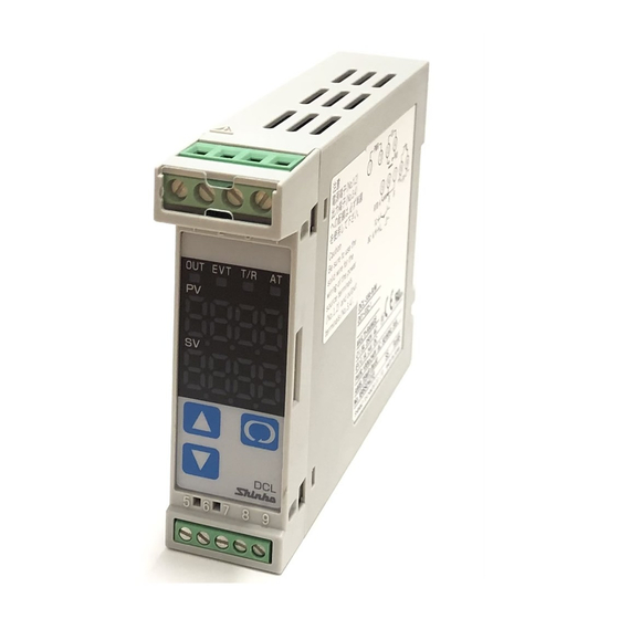
2. Name and Functions of Controller ① ③ ② ④ ⑤ ⑥ ⑦ ⑨ ⑧ ⑩ (Fig. 2-1) Description Name The red LED lights up when Event output [Alarm, Loop break alarm or Heater EVT indicator ① burnout alarm (W option)] is ON. The red LED also lights when control output OUT2 (DC option) is ON. -
Page 7: Mounting To The Control Panel
3. Mounting to the Control Panel 3.1 Site Selection This instrument is intended to be used under the following environmental conditions (IEC61010-1): Overvoltage category , Pollution degree 2 Ensure the mounting location corresponds to the following conditions: • A minimum of dust, and an absence of corrosive gases •... -
Page 8: Mounting To And Removal From The Din Rail
3.4 Mounting to and Removal from the DIN Rail Caution • Mount the DIN rail horizontally. When the DIN rail is mounted vertically, be sure to use commercially available fastening plates at both ends of the DCL-33A series. However, if the DIN rail is mounted horizontally in a position susceptible to vibration or shock, the fastening plates must be used as well. -
Page 9: Wiring
4. Wiring Warning Turn the power supply to the instrument OFF before wiring or checking. Working on or touching the terminal with the power switched ON may result in severe injury or death due to electrical shock. Caution • Do not leave wire remnants in the DCL-33A when wiring, because they could cause a fire or malfunction. •... -
Page 10: Terminal Arrangement
4.1 Terminal Arrangement Bottom of the unit Communi- cation C5 (RS-485) (Fig. 4.1-1) Name Description Power supply: 100 to 240 V AC or 24 V AC/DC For 24 V DC, ensure polarity is correct. Control output OUT1 Thermocouple input Resistance temperature detector input Direct current input, DC voltage input (*1) Event output... -
Page 11: Setup
5. Setup Connect mains power cable to terminals 1 and 2, and turn the power ON. The PV Display indicates sensor input characters and temperature unit, and the SV Display indicates the input range high limit value for approx. 3 seconds. (Table 5-1) (If any other value is set in [Scaling high limit], the SV Display indicates the value.) During this time all outputs and the LED indicators are in OFF status. -
Page 12: Main Setting Mode
5.1 Main Setting Mode Character Setting Item, Description, Setting Range Factory Default • Sets the SV1 (desired value) for control target. • Setting range: Scaling low limit to scaling high limit (For DC voltage and current input, the placement of the decimal point follows the selection.) 5.2 Sub Setting Mode Character Setting Item, Description, Setting Range... - Page 13 Character Setting Item, Description, Setting Range Factory Default Alarm 1 value • Sets Alarm 1 action point. • Alarm 1 value matches Alarm 1 low limit alarm value in the following cases: When ‘High/Low limits independent alarm’, ‘High/Low limit range independent alarm’ or ‘High/Low limits with standby independent alarm’...
-
Page 14: Auxiliary Function Setting Mode 1
: 19200 bps : 38400 bps Parity Even • Selects the parity. • Available only when serial communication (C5 option) is ordered. Not available if Shinko protocol is selected in [Communication protocol]. • : No parity : Even : Odd Stop bit •... -
Page 15: Auxiliary Function Setting Mode 2
5.4 Auxiliary Function Setting Mode 2 Character Setting Item, Description, Setting Range Factory Default Input type (–200 to 1370 ) • Selects a sensor type and temperature unit from thermocouple (10 types), RTD (2 types), Direct current (4 types) and DC voltage (4 types) and •... - Page 16 Character Setting Item, Description, Setting Range Factory Default OUT1 low limit • Sets the OUT1 low limit value. • Available for direct current output. Not available if OUT1 is in ON/OFF control. • Setting range: 0% to OUT1 high limit value (Direct current output type: –5% to OUT1 high limit value) OUT1 ON/OFF hysteresis •...
- Page 17 Character Setting Item, Description, Setting Range Factory Default Alarm 1 Energized/De-energized Energized • Selects Alarm 1 action Energized/De-energized. (For details, see p.18.) • Not available if No alarm action is selected in [Alarm 1 type]. • : Energized : De-energized Alarm 1 HOLD function Not holding •...
- Page 18 Sensor correction function This corrects the input value from the sensor. When a sensor cannot be set at the exact location where control is desired, the sensor-measured temperature may deviate from the temperature in the controlled location. When using multiple controllers, sometimes the measured temperatures (input value) do not match (even if SV is the same value) due to differences in sensor accuracy or dispersion of load capacities.
-
Page 19: Auxiliary Function Setting Mode 3
5.5 Auxiliary Function Setting Mode 3 Character Setting Item, Description, Setting Range Factory Default Event input DI allocation No event • Selects Event input DI function from the following. • Available only when Set value memory external selection (EI option) is selected. Input ON Input OFF Event Input Function... - Page 20 Character Setting Item, Description, Setting Range Factory Default Alarm 1 value 0 Enabled/Disabled Disabled • Selects Alarm 1 action Enabled or Disabled when Alarm 1 value is 0 (zero). • Not available if No alarm action is selected in [Alarm 1 type]. •...
- Page 21 Character Setting Item, Description, Setting Range Factory Default Alarm 2 Energized/De-energized Energized • Selects Alarm 2 action Energized/De-energized. (For details, see p.18.) • Not available if No alarm action is selected in [Alarm 2 type]. • : Energized : De-energized Alarm 2 HOLD function Not holding •...
- Page 22 Character Setting Item, Description, Setting Range Factory Default Alarm 3 value • Sets Alarm 3 action point. • Alarm 3 value matches Alarm 3 low limit alarm value in the following cases: When ‘High/Low limits independent alarm’, ‘High/Low limit range independent alarm’ or ‘High/Low limits with standby independent alarm’...
- Page 23 Character Setting Item, Description, Setting Range Factory Default Alarm 4 type No alarm action • Selects an Alarm 4 type. Note: If Alarm 4 type is changed, Alarm 4 value returns to 0 (0.0). • No alarm action High limit alarm Low limit alarm High/Low limits alarm High/Low limit range alarm...
- Page 24 Character Setting Item, Description, Setting Range Factory Default Alarm 4 hysteresis • Sets Alarm 4 hysteresis. • Not available if No alarm action is selected in [Alarm 4 type]. • Setting range: Thermocouple, RTD input: 0.1 to 100.0 DC voltage, current input: 1 to 1000 (The placement of the decimal point follows the selection.) Alarm 4 delay time 0 sec...
- Page 25 Character Setting Item, Description, Setting Range Factory Default SV fall rate /minute • Sets SV fall rate (falling value for 1 minute). When the SV is adjusted, it approaches the new SV by the preset rate-of-change ( /min, /min). When the power is turned on, the control starts from the PV, and approaches the SV by the rate-of-change ( /min, /min).
-
Page 26: Output Mv (Manipulated Variable) Indication
Character Setting Item, Description, Setting Range Factory Default Alarm 4 output Enabled/Disabled Disabled • Selects whether EVT output is used for Alarm 4 output. If Loop break alarm, Heater burnout alarm, Alarm 1, Alarm 2 and Alarm 3 output are set to “Enabled”, they utilize common output terminals. -
Page 27: Simplified Converter Function
6. Simplified Converter Function Caution • The converter function is selectable only for the Direct current output type. • When using this controller as a converter, take 1 second into consideration since input/output response time is approx. 1 second. • When switching from converter to controller function, the control parameters and values set by converter function are retained even if the function is switched to controller function. -
Page 28: Fine Adjustment Of Converter Output (4 To 20 Ma Dc)
Setting Item Setting Value Remote/Local Local (EI option) SV rise rate SV fall rate OUT1 high limit OUT1 low limit Alarm 1 to Alarm 4 types No alarm action Alarm 1 hysteresis Alarm 1 delay time Alarm 1 Energized/De-energized Energized Alarm 2 hysteresis Alarm 2 delay time Alarm 2 Energized/De-energized... -
Page 29: Converter Setting Example
6.2 Converter Setting Example [Other Inputs except 4 to 20 mA DC] Input, output conditions Input: 6 to 14 mA DC (Indication: 30.0 to 130.0) Output: 4 to 20 mA DC Setting method (1) Calculating Scaling high and low limit value of 4 to 20 mA DC Indication value per mA DC: (130.0 –... -
Page 30: Operation
7. Operation After the unit is mounted within the control panel (DIN rail) and wiring is completed, operate the unit following the procedure below. (1) Turn the power supply to the DCL-33A ON. For approx. 3 seconds after power is turned on, sensor input characters and temperature unit are indicated on the PV Display, and the input range high limit value is indicated on the SV Display. -
Page 31: Action Explanations
8. Action Explanations 8.1 OUT1 Action Heating (Reverse) action Cooling (Direct) action Proportional band Proportional band Control action Relay contact output Cycle action is performed Cycle action is performed according to deviation according to deviation Non- contact 12 V DC 0 V DC 0/12 V DC 12/0 V DC... -
Page 32: Heater Burnout Alarm Action
8.3 Heater Burnout Alarm Action Heater burnout alarm action Heater burnout alarm value Small Large Load current Indicator (EVT) Red Unlit : Event output EV terminals 8 and 9 are ON. : Event output EV terminals 8 and 9 are OFF. The Event output EVT indicator lights up when Event output EV terminals 8 and 9 are ON, and turns off when they are OFF. - Page 33 Process high alarm Process low alarm EV 1 hysteresis EV 1 hysteresis Alarm action EV 1 value EV 1 value Alarm output High limit with standby alarm Low limit with standby alarm EV1 hysteresis EV1 hysteresis Alarm action -EV1 value +EV1 value -EV1 value +EV1 value...
-
Page 34: Out2 (Heating/Cooling Control) Action
8.5 OUT2 (Heating/Cooling Control) Action OUT1 P-band OUT2 P-band Control Heating Cooling action action action Relay contact output Cycle action is performed according to deviation. Non-contact 12 V DC 12/0 V DC 0 V DC voltage output Cycle action is performed according to deviation. -
Page 35: Out2 (Heating/Cooling Control) Action (When Setting Overlap Band)
8.6 OUT2 Action (When Setting Overlap Band) OUT1 P-band OUT2 P-band Overlap band Control Heating Cooling action control control Relay contact output Cycle action is performed according to deviation. Non-contact 12 V DC 12/0 V DC 0 V DC voltage output Cycle action is performed according to deviation. -
Page 36: Out2 (Heating/Cooling Control) Action (When Setting Dead Band)
8.7 OUT2 Action (When Setting Dead Band) OUT1 P-band Dead band (OUT2 P-band) Cooling Heating Control action action action Relay contact output Cycle action is performed according to deviation. Non-contact 12 V DC 12/0 V DC 0 V DC voltage output Cycle action is performed according to deviation. -
Page 37: At (Auto-Tuning)
9. AT (Auto-tuning) In order to decide each value of P, I, D and ARW automatically, the auto-tuning process should be made to fluctuate to obtain an optimal value. One of 3 types of fluctuation below is automatically selected. For DC input, the AT process will fluctuate around the SV for conditions of (A), (B) and (C). Sometimes the auto-tuning process will not fluctuate if auto-tuning is performed at or near room temperature. -
Page 38: Specifications
10. Specifications 10.1 Standard Specifications Model: DIN rail mounted indicating controller Mounting: DIN rail Setting: Input system using membrane sheet key Display: PV Display: Red LED 4 digits, character size 7.4 x 4.0 mm (H x W) SV Display: Green LED 4 digits, character size 7.4 x 4.0 mm (H x W) Input: Thermocouple: K, J, R, S, B, E, T, N, PL- , C (W/Re5-26) External resistance: 100 max. - Page 39 EVT output: • Alarm output [Alarm, Loop break alarm and Heater burnout alarm (W option) utilize common output terminals.] The alarm action point is set by deviation from the SV (excluding Process alarm), and when input goes outside the range, alarm output is turned ON or OFF (High/Low limit range alarm). When De-energized is selected in [Alarm Energized/De-energized], alarm output is activated conversely.
- Page 40 [Input error indication] Output status Output Controller/Converter Contents status Controller Converter when input OUT1 OUT2 OUT1 errors occur Indication (*1) Direct Reverse Direct Reverse Direct action Reverse action ON (20 mA) 20 mA 4 mA or OUT1 high OFF (4 mA) “...
-
Page 41: Optional Specifications
Insulation/Dielectric strength: Circuit insulation configuration CT input Input Set value memory External setting input Communicatio Electrically insulated Power supply Insulation resistance: 10 M minimum, at 500 V DC Dielectric strength: 1.5 kV AC for 1 minute Power supply: 100 to 240 V AC 50/60 Hz, 24 V AC/DC 50/60 Hz Allowable voltage fluctuation range: 100 to 240 V AC: 85 to 264 V AC, 24 V AC/DC: 20 to 28 V AC Power consumption: 100 to 240 V AC: Approx. - Page 42 Synchronization method: Start-stop synchronization Data bit/Parity: 7, 8/Even, Odd, No parity (Selectable by keypad) Stop bit: 1, 2 (Selectable by keypad) Communication protocol: Shinko protocol/Modbus ASCII/Modbus RTU (Selectable by keypad) (Default: Shinko protocol) Data format: Communication protocol Shinko protocol Modbus ASCII...
- Page 43 Set value memory external selection (EI option) Switches SV1 and SV2 by external contact. If 001 is selected in [Event input DI allocation]: DI input Open: SV1 DI input Closed: SV2 If 008 is selected in [Event input DI allocation]: DI input Open: SV2 DI input Closed: SV1 Circuit current when closed: Approx.
-
Page 44: Troubleshooting
11. Troubleshooting If any malfunctions occur, refer to the following after checking that power is being supplied to the controller. 11.1 Indication Problem Possible Cause Solution Burnout of thermocouple, RTD or Replace each sensor. ] is flashing on disconnection of DC voltage How to check whether the sensor the PV Display. -
Page 45: Key Operation
Problem Possible Cause Solution The value set in Check whether the input signal wire How to check whether the input [Scaling low limit] for DC voltage (0 to 5 V DC, 0 to 10 signal wire is disconnected remains on the PV V DC) or direct current (0 to 20 mA [DC voltage (0 to 5 V DC, 0 to 10 V Display. -
Page 46: Control
11.3 Control Problem Possible Cause Solution The PV (temperature) The sensor is out of order. Replace the sensor. does not rise. Check whether the sensor is Mount the sensor or control output securely mounted to the instrument terminals securely. input terminals, or control output terminals are securely mounted to the actuator input terminals. -
Page 47: Character Table
12. Character Table 12.1 Main Setting Mode Character Setting Item, Description, Setting Range Factory Default Scaling low limit to scaling high limit (For DC voltage and current input, the placement of the decimal point follows the selection.) 12.2 Sub Setting Mode Character Setting Item, Description, Setting Range Factory Default... -
Page 48: Auxiliary Function Setting Mode 1
Communication protocol Shinko protocol : Shinko protocol : Modbus ASCII mode : Modbus RTU mode : Shinko protocol (Block read available) : Modbus ASCII mode (Block read available) : Modbus RTU mode (Block read available) Instrument number 0 to 95... -
Page 49: Auxiliary Function Setting Mode 2
12.4 Auxiliary Function Setting Mode 2 Character Setting Item, Setting Range Factory Default Input type (-200 to 1370 ) -200 to 1370 -320 to 2500 -199.9 to 400.0 -199.9 to 750.0 -200 to 1000 -320 to 1800 0 to 1760 0 to 3200 0 to 1760 0 to 3200... - Page 50 Character Setting Item, Setting Range Factory Default OUT2 high limit 100% OUT2 low limit value to 100% OUT2 low limit 0% to OUT2 high limit value Overlap/Dead band Thermocouple, RTD input: –100.0 to 100.0 DC voltage, current input: 1 to 1000 (The placement of the decimal point follows the selection.) OUT2 ON/OFF hysteresis Thermocouple, RTD input: 0.1 to 100.0...
-
Page 51: Auxiliary Function Setting Mode 3
12.5 Auxiliary Function Setting Mode 3 Character Setting Item, Setting Range Factory Default No event Event input DI allocation Input ON Input OFF Event Input Function (Closed) (Open) No event Set value memory Control ON/OFF Control OFF Control ON Direct/Reverse action Direct Reverse Preset output 1 ON/OFF... - Page 52 Character Setting Item, Setting Range Factory Default Alarm 2 value 0 Enabled/Disabled Disabled : Disabled : Enabled Alarm 2 value See (Table 12.2-1) on p.48. (For DC voltage and current input, the placement of the decimal point follows the selection.) Alarm 2 high limit alarm value See (Table 12.2-1) on p.48.
- Page 53 Character Setting Item, Setting Range Factory Default Not holding Alarm 3 HOLD function : Not holding : Holding Alarm 3 hysteresis Thermocouple, RTD input: 0.1 to 100.0 DC voltage, current input: 1 to 1000 (The placement of the decimal point follows the selection.) 0 sec Alarm 3 delay time 0 to 9999 sec...
- Page 54 Character Setting Item, Setting Range Factory Default 1370 External setting input high limit External setting input low limit to Scaling high limit –200 External setting input low limit Scaling low limit to External setting input high limit SV start SV Rise/Fall rate start type : SV start : PV start /minute...
- Page 56 No. DCL32E4 2018.05...
Need help?
Do you have a question about the DCL-33A-R/M and is the answer not in the manual?
Questions and answers