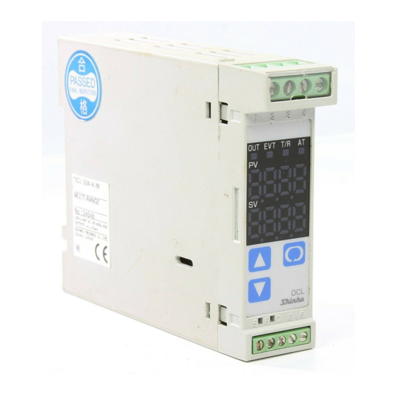
Shinko DCL-33A Instruction Manual
Din rail mounting type indicating controller
Hide thumbs
Also See for DCL-33A:
- Instruction manual (56 pages) ,
- Communication instruction manual (40 pages) ,
- Instructions manual (21 pages)
Advertisement
Instruction manual
To prevent accidents arising from the misuse of this controller, please ensure the operator using it
receives this manual.
Caution
• This instrument should be used according to the specifications described in this manual.
If it is not used according to the specifications, it may malfunction or breakdown.
• Be sure to follow the warnings, cautions and notices. If not, serious injury or accidents may occur.
• The specifications of the DCL-33A and the contents of this instruction manual are subject to change
without notice.
• Care has been taken to assure that the contents of this instruction manual are correct, but if there are
any doubts, mistakes or questions, please inform our sales department.
• Be sure to check that the power is turned off when cleaning this instrument.
• Use a soft and dry cloth when cleaning the instrument.
(If paint thinner is used, it might deform or tarnish the unit.)
• As the display section is vulnerable, do not strike or scratch it with a hard object.
• Any unauthorized transfer or copying of this document, in part or in whole, is prohibited.
• Shinko Technos is not liable for any damages or secondary damages incurred as a result of
using this product, including any indirect damages.
1. Model name
1.1 Model name
DCL-3
Control action 3
Alarm
Control output
Input
Option
*1: Alarm action (9 types and no alarm) and Energized/Deenergized are selectable by key operation.
*2: Thermocouple, RTD, DC current and DC voltage are selectable by key operation.
1.2 How to indicate model name label
Model name label is on the right side of the case and the bottom of the inner assembly.
In the case of Heater burnout alarm output, CT rated current value is written in the bracket ( ).
Model name ----------------------------------
Option ------------------------------------------
Option ------------------------------------------
Instrument No. (Inner assembly only)--
DIN rail mounting type indicating controller
3 A-
/
,
A
R
S
A
M
W (5A)
W (10A)
W (20A)
W (50A)
C5
Series name: DCL-300 (W22.5 x H75 x D100mm)
PID
Alarm action is selectable by key operation *1
Relay contact: 1a
Non-contact voltage (for SSR drive): 12
DC current: 4 to 20mAdc
Multi-range *2
Heater burnout alarm
Serial communication
DCL-33A-R/M
Relay contact output/ Multi-range input
Heater burnout alarm output
W (20A)
No. XXXXXX
1
DCL-33A
No.DCL31E1 .
,
Vdc
+2
-0
CT rated current: 5A
CT rated current: 10A
CT rated current: 20A
CT rated current: 50A
Based on EIA RS-485
Advertisement
Table of Contents

Related Manuals for Shinko DCL-33A


Summary of Contents for Shinko DCL-33A
- Page 1 If it is not used according to the specifications, it may malfunction or breakdown. • Be sure to follow the warnings, cautions and notices. If not, serious injury or accidents may occur. • The specifications of the DCL-33A and the contents of this instruction manual are subject to change without notice.
-
Page 2: Operation
2. Name and functions of the sections (1) Event (EVT) output action indicator A red LED lights when Event output [Alarm, Loop break alarm or Heater burnout alarm (Option)] is ON. (2) Control output (OUT) action indicator A green LED lights when the control output (OUT) is ON. (3) Serial communication output indicator A yellow LED blinks while serial communication TX (sending) is output. -
Page 3: Operation Flow Chart
3.1 Operation flow chart PV/SV display mode Control output MV indication (Approx. 3s) (Approx. 3s) (Approx. 3s) [Main setting mode] [Sub setting mode] Auxiliary function setting mode 1 Auxiliary function setting mode 2 Main setting PID auto-tuning Perform/Cancel Setting value lock selection Sensor selection Proportional band setting Sensor correction setting... -
Page 4: Initial Value
3.2 Main setting mode Character Name, Description, Setting range Initial value Main setting M: 0 • Set the value for controlled objects. • Scaling low limit setting value to Scaling high limit setting value (Decimal point place follows the selection for DC current input) 3.3 Sub setting mode Name, Description, Setting range Initial value... - Page 5 Initial value Character Name, Description, Setting range Heater burnout alarm setting 0.0A • Sets the heater current value for Heater burnout alarm. • Setting the value to 0.0 disables this function. • Self-holding is not available for the alarm output. When alarm and Loop break alarm are applied together, the output is common.
- Page 6 Sensor correction setting M: 0.0 • Sets the sensor correction value of the sensor. • Thermocouple and RTD input: -100.0 to 100.0 ( ) DC voltage and DC current input: -1000 to 1000 (Decimal point place follows the selection.) Instrument number setting •...
- Page 7 Character Name, Description, Setting range Initial value PV filter time constant setting 0.0 seconds • Sets the PV filter time constant. If the setting value is too large, it affects control result due to the response delay. • 0.0 to 10.0 seconds Control output high limit setting 100% •...
- Page 8 Alarm action delayed timer setting 0 seconds • Sets the alarm action delayed time. Alarm output activates when the setting time has passed after the input enters alarm output range. • This setting item is not indicated when “No alarm” action is selected in [Alarm action selection].
-
Page 9: Name And Description
3.6 Control output manipulated variable indication Name and Description Control output manipulated variable indication Press the key for approx. 3 seconds during PV/SV indication mode. Keep pressing the key until the output manipulated variable shows up, though the main setting mode appears during the process. (The control output manipulated variable is indicated on the SV display and the decimal point at the second digit blinks in 0.5 seconds cycle.) Pressing the... - Page 10 When mounting and wiring to the control panel (DIN rail) are finished, running starts following the next procedure. (1) Turn the power supply to the DCL-33A ON. For approx. 3s after power on, the character of the sensor type and temperature unit are indicated on the PV display, and the rated maximum value is indicated on the SV display.
-
Page 11: Action Explanations
7. Action explanations 7.1 Standard action Action Heating (reverse)action Cooling (direct)action Proportional band Proportional band Control action Main setting Main setting Relay contact output Cycle action according to deviation Cycle action according to deviation 12Vdc 12/0Vdc 0Vdc 0Vdc 0/12Vdc 12Vdc Non-contact voltage output Cycle action according to deviation... -
Page 12: Heater Burnout Alarm Action
7.3 Alarm action High limit alarm Low limit alarm High/Low limits alarm Alarm hysteresis Alarm hysteresis Alarm hysteresis Alarm action - Alarm setting + Alarm setting - Alarm setting Main + Alarm setting Main Alarm setting Main Alarm setting point point point setting... - Page 13 8. PID auto-tuning of the DCL-33A In order to decide each P, I, D value and ARW automatically, this system gives a fluctuation to the controlled object to get a optimal value. 3 types of fluctuation below are automatically selected.
-
Page 14: Mounting To The Control Panel
When DIN rail is mounted vertically, be sure to use commercially available fastening plates at the end of DCL-33A. Mount the DCL-33A to the DIN rail so that the DCL-33A cannot move. However, if the DIN rail is mounted horizontally in a position susceptible to vibration or shock, the fastening... - Page 15 (1) Hook (1) of DCL-33A on the upper side of the DIN rail. (Fig. 9.4-1) (2) Making the (1) part of the DCL-33A as a support, fit the lower part of the DCL-33A to the DIN rail. DCL-33A will be completely fixed to DIN rail with a “Click” sound. (Fig.9.4-1) (Fig.9.4-1)
-
Page 16: Specifications
* Note Tighten the terminal screw properly referring to the table below. Terminal screw Terminal No. Torque M2.6 (1) to (4) Max. 0.5N・m M2.0 (5) to (9) Max. 0.25N・m • Terminal arrangement Lower part of main body Power 24Vdc 24Vac or 100 to 240Vac Communication (RS-485) - Page 17 • Non-contact voltage (for SSR drive): 12 Vdc Max. 40mA (Short-circuit protected) +2 -0 Shinko SSR (SA-200 series): 4 units connectable parallel • DC current : 4 to 20mAdc, Load resistance: Max. 550 Output accuracy: Within 0.3% of output span...
- Page 18 Setting accuracy: The same as indicating accuracy Action: ON/OFF action Hysteresis: Thermocouple and RTD input: 0.1 to 100.0 ( ) [Factory adjusted as 1.0 ] DC voltage and current input: 1 to 1000 [Factory adjusted as 10] (Decimal point place follows the selection.) Output: Open collector Control capacity 24Vdc 0.1A (Max.) Alarm (EVT) output action: Alarm action is selectable from below by front key operation.
- Page 19 When the value is set from SVTC bias setting of DCL-33A, the desired value is the one that adds SVTC bias value to the received value from PC-900 series by external digital setting.
-
Page 20: Troubleshooting
• If you have any inquiries, please consult our agency or the shop where you purchased the unit. SHINKO TECHNOS CO.,LTD. OVERSEAS DIVISION 2-48, 1-Chome, Ina, Minoo, Osaka, Japan Reg. Office P.O.Box 17, Minoo, Osaka, Japan...
Need help?
Do you have a question about the DCL-33A and is the answer not in the manual?
Questions and answers