
Related Manuals for Ingersoll-Rand 7790-A Series


Summary of Contents for Ingersoll-Rand 7790-A Series
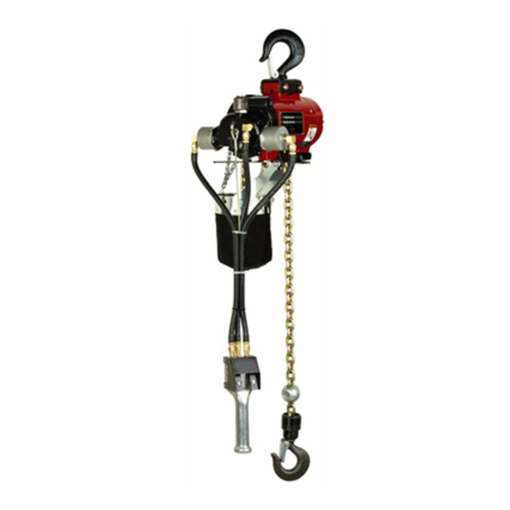
- Page 1 Form 10590149 Edition 2 September 2005 HOISTS Series 7790-A & 7792-A Operator’s Manual Save These Instructions...
-
Page 2: Air Supply Requirements
Safety Information Operating Precautions To aid the operator’s understanding of proper and safe use of hoists, the publication “OVERHEAD HOISTS”, ANSI B30.16-1981, can be purchased from: American Standards Institute, Inc. 1430 Broadway New York, New York 10018 • Do not use the hoist described in this manual to lift or transport humans. -
Page 3: Adjusting Brake
Adjusting Brake • Properly attach rated load of hoist to load chain hook. • Slowly raise load to 6” height above floor by slowly pulling pull chain handle or depressing pendent control. • Release pull chain handle or pendent control. •... -
Page 4: Routine Inspection
Routine Inspection The type of application for a hoist varies so greatly it is impractical to recommend an exact time-table for inspection of the hoist. Where hoist is subjected to continuous operation with capacity loads, it is recommended the unit be inspected twice a week. -
Page 5: Motor Disassembly
Maintenance Dissassembly Head Disassembly To remove head section from housing without disassembling head components, remove head with control rod (59) attached to gear (25). To accomplish this - - Remove two screws (96) and housing cap (95). - Drive out roll pin (61) and remove brake block (60). - Drive out roll pin (69) from control arm (68). -
Page 6: Housing Disassembly
- Assemble motor to housing. - Lubricate and assemble o-rings (35) into counterbore of end plate (38). - Assemble new gasket (31) and head to housing. Brake and Gearing Disassembly - Remove two screws (96) and housing cap (95). - Carefully slide brake spring (94) part way off brake shoes (92) and using brake spring spreader (33541), remove brake spring (94). - Page 7 Upper Hook Disassembly - Remove nuts (153), washers (152) and bracket (150). - Drive out roll pin (147) - One-Ton Models. Roll pins (155) and (154) - Two-Ton Models. - Remove collar (143) and balls (144) - One-Ton Models. Collar (116), thrust bearing (120) and bearing races (119) - Two-Ton Models.
- Page 8 CAUTION: TIGHTEN NUTS 25 TO 30 FT. LBS. TORQUE ONLY. 94 92 Form 10590149-Edition 2...
- Page 9 ( 2-TON MODELS) 123 ( 1-TON MODELS) 149 (1-TON MODELS) PART NUMBER THIS SIDE. Form 10590149-Edition 2 122 ( 2-TON MODELS) 148 ( 1-TON MODELS) ++ ASSEMBLE WITH SPLIT SIDE ONE UP AND ONE DOWN. + ASSEMBLE WITH SPLIT SIDE ONE UP OR DOWN. (2-TON MODELS) DOWN ITEMS INCLUDED IN SERVICE KIT PART NUMBER 41619-1.
-
Page 10: Parts List
Parts List Sl. no. Description Head Assembly (standard models) includes items 1 thru 21, 24 thru 30, 33 and 34 with adapter (46211) Head Assembly (spark-resistant models) (includes items 1 thru 19, 24 thru 30, 33, 34 and 59 with adapter 46212) Adapter for standard models for spark-resistant models... - Page 11 Parts List Sl. no. Description * 74 Cotter Pin Carrier Bearing Race (4 req'd) Gear (2 req'd) Shaft (2 req'd) Spacer * 80 Bearing * 81 Bearing * 82 Retaining Ring * 83 Retaining Ring Gearing Assembly (includes items 70 thru 73 and 75 thru 83) Fixed Ring Gear Roll Pin (2 req'd)
- Page 12 Parts List Sl. no. Description Roll Pin * 148 Safety Latch (includes bolt, nut and spring) Hook Steel Hook for standard 1 ton models Bronze Hook for 1500 lb spark-resistant models LOWER HOOK ASSEMFLY for 1 ton models (includes items 143 thru 145 and 147 thru 149 with steel hook) LOWER HOOK ASSEMBLY for 1500 lb spark-resistant models (includes items 143...
-
Page 13: Model Identification
Model Identification Model No. Upper Mounting 7790-A9 Hook Ass’y 43002 7790-A11 7790-A13 Hook Ass’y 43002 7790-A15 7792-A9 Hook Ass’y 43049 7792-A11 7792-A13 Hook Ass’y 43049 7792-A15 Spark Resistant Models Model No. Upper Mounting 7790-A21 Hook Ass’y 43097 7790-A22 7792-A21 Hook Ass’y 43096 7792-A22 7792-A23 Hook Ass’y 43096... - Page 14 Notes Form 10590149-Edition 2...
- Page 15 Notes Form 10590149-Edition 2...
- Page 16 Ingersoll-Rand © 2005 Company...
Need help?
Do you have a question about the 7790-A Series and is the answer not in the manual?
Questions and answers