Table of Contents
Advertisement
Quick Links
Advertisement
Table of Contents

Related Manuals for SOYO SY-6VBA 133


Summary of Contents for SOYO SY-6VBA 133
- Page 1 SY-6VBA 133 Motherboard **************************************************** ® ® Pentium III, Pentium II & Celeron™ Processor supported Apollo Pro133 AGP/PCI Motherboard 66/100/133 MHz Front Side Bus supported ATX Form Factor **************************************************** User's Manual...
- Page 2 It is the policy of Soyo Computer Inc. to respect the valid patent rights of third parties and not to infringe upon or to cause others to infringe upon such rights.
-
Page 3: Table Of Contents
Table of Contents CHAPTER 1 MOTHERBOARD DESCRIPTION ......1 INTRODUCTION ............1 KEY FEATURES ............1 HANDLING THE MOTHERBOARD ......5 ELECTROSTATIC DISCHARGE PRECAUTIONS ..5 SY-6VBA 133 MOTHERBOARD LAYOUT....6 SY-6VBA 133 MOTHERBOARD COMPONENTS ..7 MICROPROCESSOR............9 MEMORY...............9 CHIPSET ..............11 1-10 I/O INTERFACE CONTROLLER .........13 1-11 HARDWARE MONITOR..........16... - Page 4 Table of Contents SY-6VBA 133 SOYO COMBO SETUP ..........53 STANDARD CMOS SETUP .........59 BIOS FEATURES SETUP..........62 CHIPSET FEATURES SETUP ........67 POWER MANAGEMENT SETUP........70 PNP/PCI CONFIGURATION SETUP......74 LOAD SETUP DEFAULTS...........77 INTEGRATED PERIPHERALS ........77 SUPERVISOR PASSWORD..........82 3-10 USER PASSWORD............83 3-11 IDE HDD AUTO DETECTION........84...
-
Page 5: Chapter 1 Motherboard Description
6VBA 133 as well. Ø CPU SETTINGS The SY-6VBA 133 provides the user with a very complete and convenient CPU setting environment. The CPU settings are all adjusted through the special SOYO COMBO page in the BIOS, therefore rendering the use of jumpers obsolete. - Page 6 CPU Core Voltage The CPU Core voltage is set automatically according to CPU needs. The SY-6VBA 133 supports an advanced Core voltage feature; it can be adjusted through the BIOS directly without setting jumper. In normal mode the voltage will be standard, apart from that the user can specify increments of 2.5%, 5%, 7.5% and 10% on top of the standard voltage.
-
Page 7: Hardware Monitor
The SY-6VBA 133 supports booting from devices such as CD-ROM. Power on by modem or alarm If the SY-6VBA 133 system is in suspend mode, it can be switched back on through the modem or RTC alarm through this function. This opens a lot of possibilities, such as remote access that switches the system on only after the modem receives a call. - Page 8 Motherboard Description SY-6VBA 133 Year 2000 compliant PC98 compliant FCC/CE complaint Ø USER FRIENDLY SOYO Combo Setup Jumperless design You can set up the following options trough the BIOS setting CPU FSB frequency CPU multiplier CPU Vcore voltage ...
-
Page 9: Handling The Motherboard
Motherboard Description SY-6VBA 133 HANDLING THE MOTHERBOARD To avoid damage to your Motherboard, follow these simple rules while unpacking: Ø Before handling the Motherboard, ground yourself by grasping an unpainted portion of the system's metal chassis. Ø Remove the Motherboard from its anti-static packaging. Hold the Motherboard by the edges and avoid touching its components. -
Page 10: Sy-6Vba 133 Motherboard Layout
Motherboard Description SY-6VBA 133 1-5 SY-6VBA 133 MOTHERBOARD LAYOUT PS/2 KB PS/2 Mouse JP10 Connector Connector LED1 DIMM 1 DIMM 1 USB 1 USB 2 Slot 1 DIMM 2 CPUFAN ® DIMM 3 DIMM 4 COM 1 ® COM 2... -
Page 11: Sy-6Vba 133 Motherboard Components
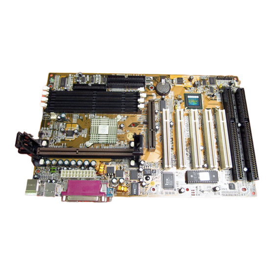
Motherboard Description SY-6VBA 133 1-6 SY-6VBA 133 MOTHERBOARD COMPONENTS... - Page 12 Motherboard Description SY-6VBA 133 ATX Power Supply Connector Slot 1 Connector Power On by Keyboard Jumper Via 82C693A PCI/AGP North Bridge chip CPU B21 and A14 setting Jumper CPU Cooling Fan Connector DIMM Bank 5V Stand-by indicator LED Floppy Disk Drive (FDD) Port...
-
Page 13: Microprocessor
Motherboard Description SY-6VBA 133 1-7 MICROPROCESSOR The motherboard supports a single Slot 1 processor. The processor’s VID pins automatically program the voltage regulator on the motherboard to the required processor voltage. In addition, the front side bus speed (66 MHz, 100 MHz and 133 MHz) is automatically selected. The motherboard supports all current Slot 1 processor speeds, voltages, and bus frequencies. - Page 14 Motherboard Description SY-6VBA 133 two, three, or four sockets. Using the serial presence detect (SPD) data structure, programmed into an E²PROM on the DIMM, the BIOS can determine the SDRAM’s size and speed. Minimum DIMM memory size is 8 MB; maximum DIMM memory size is 256/512 MB. Memory size and speed can vary between sockets.
-
Page 15: Chipset
Motherboard Description SY-6VBA 133 1-8.3 ECC Memory ECC memory detects multiple-bit errors and corrects single-bit errors. When ECC memory is installed, the BIOS supports both ECC and non- ECC mode. ECC mode is enabled in the Setup program. The BIOS automatically detects if ECC memory is installed and provides the Setup option for selecting ECC mode. - Page 16 Motherboard Description SY-6VBA 133 The VT82C6893A system controller also supports full AGP v1.0 capability for maximum bus utilization including 2x mode transfers, SBA (Side Band Addressing), Flush/Fence commands, and pipelined grants. An eight level request queue plus a four level post-write request queue with thirty-two and sixteen quad words of read and write data FIFO’s...
-
Page 17: I/O Interface Controller
Motherboard Description SY-6VBA 133 extended 256 byte CMOS RAM, integrated master mode enhanced IDE controller with full scatter/ gather capability and extension to UltraDMA- 33/66 for 33/66 MB/sec transfer rate, integrated USB interface with root Hub and two function ports with built-in physical layer transceivers, Distributed DMA supports, and On Now/ ACPI compliant advanced configuration and power management interface. -
Page 18: Serial Ports
Motherboard Description SY-6VBA 133 1-10.1 Serial Ports The motherboard has two 9-pin D-Sub serial port connectors located on the back panel. The NS16C5450-compatible UARTs support data transfers at speeds up to 115.2 Kbits/sec with BIOS support. 1-10.2 Parallel Port The connector for the multimode bi-directional parallel port is a 25-pin D- Sub connector located on the back panel of the motherboard. -
Page 19: Infrared Support
Motherboard Description SY-6VBA 133 ¿ Note The mouse and keyboard can be plugged into either PS/2 connector. Power to the computer should be turned off before a keyboard or mouse is connected or disconnected. The keyboard controller contains code, which provides the traditional keyboard and mouse control functions, and also supports Power On/Reset password protection. -
Page 20: Hardware Monitor
Motherboard Description SY-6VBA 133 1-11 HARDWARE MONITOR The optional hardware monitor subsystem provides low-cost instrumentation capabilities. The features of the hardware monitor subsystem include: Ø An integrated ambient temperature sensor Ø Fan speed sensors, which monitor the fan 1 and fan 2 connector. -
Page 21: Chapter 2 Hardware Installation
SY-6VBA 133 Chapter 2 HARDWARE INSTALLATION Congratulations on your purchase of SY-6VBA 133 Motherboard. You are about to install and connect your new Motherboard. Note: Do not unpack the Motherboard from its protective anti- static packaging until you have made the following preparations. -
Page 22: Unpacking The Motherboard
Hardware Installation SY-6VBA 133 UNPACKING THE MOTHERBOARD When unpacking the Motherboard, check for the following items: u The SY-6VBA 133 Apollo Pro133 AGP/PCI Motherboard u The Quick Start Guide u The Installation CD-ROM u SOYO 3-in-1 Bonus Pack CD-ROM (Norton... -
Page 23: Installation Guide
Hardware Installation SY-6VBA 133 2-3 INSTALLATION GUIDE We will now begin the installation of the Motherboard. Please follow the step-by-step procedure designed to lead you to a complete and correct installation. Warning: Turn off the power to the Motherboard, system chassis, and peripheral devices before performing any work on the Motherboard or system. -
Page 24: 2-3.1 Cpu Fan Installation
Hardware Installation SY-6VBA 133 2-3.1 CPU Installation Your SY-6VBA 133 motherboard comes with a CPU retention set kit. The retention set is used to hold the processor attached to the Slot 1 CPU connector on the motherboard. Record the working frequency of Mark your CPU Frequency: your CPU that should be clearly marked on the CPU cover. - Page 25 Hardware Installation SY-6VBA 133 Open the two sides by folding them up. Push the locks on top of the CPU inward.
- Page 26 Hardware Installation SY-6VBA 133 Insert the CPU into the retention module. The CPU fits in the CPU slot in only ONE way, do not try to force it in. After completely inserting the CPU, push the two locks on top of the CPU outward.
- Page 27 Hardware Installation SY-6VBA 133 Note: Installing a heat sink and cooling fan on top of your CPU is necessary for proper heat dissipation. Failing to install these items may result in overheating and possible burn-out of your CPU. 2-3.1.1 CPU Fan Installation Your Slot 1 processor kit comes with a cooling fan.
-
Page 28: 2-3.2 Sdram Memory Module Installation
Hardware Installation SY-6VBA 133 2-3.2 SDRAM Memory Module Installation ® ® ® Your board comes with four DIMM sockets, providing support for up to 1.5GB of main memory using unbuffered and registered DIMM modules from 8MB to 256/512MB. On this motherboard, DRAM speed can be set independent from the CPU front side bus speed. -
Page 29: Memory Configuration Table
Hardware Installation SY-6VBA 133 Memory Configuration Table Number of DIMM 1 DIMM 2 DIMM 3 DIMM 4 Memory Modules RAM Type SDRAM Memory Module 8/16/32/64/128/256/512 MB 8/16/32/64/128/256 MB Size (MB) (For DIMM1& DIMM2) (For DIMM3 & DIMM4) Note: Always install memory modules in the order prescribed in this... -
Page 30: 2-3.3 Motherboard Connector
Hardware Installation SY-6VBA 133 2-3.3 Motherboard Connector 2-3.3.1 IDE Device Installation (HDD, CD-ROM) ® ® Pin -1 IDE 2 IDE 1 ® Secondary Primary This Motherboard offers two primary and secondary IDE device connectors (IDE1, IDE2). It can support up to four high-speed Ultra DMA 33HDD or CD-ROM. -
Page 31: Floppy Drive Installation
Hardware Installation SY-6VBA 133 2-3.3.2 Floppy Drive Installation ® ® Pin -1 Floppy Drive Connector ® The system supports 5 possible floppy drive types: 720 KB, 1.2 MB, 1.44 MB, 2.88 MB, and LS-120. In addition, this Motherboard supports a 3-mode (720KB/1.2MB/1.44MB) floppy commonly used in Japan. - Page 32 Hardware Installation SY-6VBA 133 2-3.3.3 Front Panel Connections ® HDD LED Speaker ® Turbo LED Key Lock PWRBT ® Power LED Reset Plug the computer case's front panel devices to the corresponding headers on the Motherboard. 1. Power LED & KeyLock Plug the Power LED cable into the 5-pin Keylock header.
- Page 33 Hardware Installation SY-6VBA 133 2. Reset Plug the Reset push-button cable into the 2-pin Reset header on the Motherboard. Pushing the Reset button on the front panel will cause the system to restart the boot-up sequence. Reset Pin Assignment Power Good 3.
- Page 34 Hardware Installation SY-6VBA 133 5. IDE LED Attach the 2-pin IDE device LED cable to the corresponding IDE LED header on the Motherboard. This will cause the LED to lighten when an IDE (HDD, CD-ROM) device is active. HDD LED Pin Assignment LED Anode LED Cathode 6.
- Page 35 Hardware Installation SY-6VBA 133 2-3.3.4 Back Panel Connections All external devices such as the PS/2 keyboard, PS/2 mouse, printer, modem, USB can be plugged directly onto the Motherboard back panel. Only after you have fixed and locked the Motherboard to the computer case can you start connecting the external peripheral devices.
- Page 36 Hardware Installation SY-6VBA 133 1. Onboard Serial Ports COM1/COM2 External peripherals that use serial transmission scheme include: serial mouse, and modem. Plug the serial device cables directly into the COM1/COM2 9-pin male connectors located at the rear panel of the Motherboard.
- Page 37 Hardware Installation SY-6VBA 133 5. Universal Serial Bus USB1/USB2 This Motherboard provides two USB ports for your additional devices. Plug the USB device jack into the available USB connector USB1 or USB2. USB devices under Win98 are allowed. With Win95, use the UHCI specifications.
- Page 38 Hardware Installation SY-6VBA 133 2-3.3.5 Other Connections 1. Wake-On-LAN (WOL) Attach the 3-pin connector from the LAN card which supports the Wake- On-LAN (WOL) function to the JP44 header on the Motherboard. This WOL function lets users wake up the connected computer through the LAN card.
- Page 39 Hardware Installation SY-6VBA 133 2. Infrared (IR1) Plug the 5-pin infrared device cable to the IR1 header. This will enable the infrared transfer function. This Motherboard meets both the ASKIR and HPSIR specifications. Please install according to the following pin assignment:...
- Page 40 Hardware Installation SY-6VBA 133 4. Cooling Fan Installation (1) CPU Cooling Fan After you have seated the CPU properly on the processor, attach the 3-pin fan cable to the CPUFAN connector on the Motherboard. The fan will stop when the system enters into Suspend Mode. (Suspend mode can be enabled from the BIOS Setup Utility, [POWER MANAGEMENT] menu.)
- Page 41 Hardware Installation SY-6VBA 133 (2) Chassis Cooling Fan Some chassis also feature a cooling fan. This Motherboard features a CHAFAN connector to provide 12V power to the chassis fan. Connect the cable from the chassis fan to the CHAFAN 3-pin connector. Install...
-
Page 42: Atx Power
Hardware Installation SY-6VBA 133 2-3.3.6 AGP VGA Card Insert the AGP VGA card into the AGP slot. Then connect the monitor information cable to the AGP card back plane external connector. Follow the manufacturer's instructions to perform the AGP VGA drivers installation. - Page 43 Hardware Installation SY-6VBA 133 Warning: Follow these precautions to preserve your Motherboard from any remnant currents when connecting to ATX power supply: Turn off the power supply and unplug the power cord of the ATX power supply before connecting to ATX PW connector.
-
Page 44: Jumper Setting
Hardware Installation SY-6VBA 133 2-3.4 Jumper Setting Step 1. 5V Stand-by indicator LED (LED 1) This LED is lit whenever the 5V Standby voltage coming from the ATX power supply is available. If you have connected your ATX power supply to the motherboard, LED 1 should be lit. - Page 45 & JP9 while setting a different (higher) FSB Frequency in the BIOS may allow the user to set a higher multiplier value. Doing so will however force your CPU to operate out of its specifications, and therefore SOYO can not guarantee the proper functioning of your system.
- Page 46 Hardware Installation SY-6VBA 133 Refer to the following table: PII, PII,PIII PIII Celeron tell CPU its FSB Speed 66MHz 100MHz 133MHz Possible Normal Short FSB = 66MHz Short higher multiplier setting setting FSB = Short Normal setting Open 100MHz Normal...
-
Page 47: 2-3.5 Cmos Clearing (Jp5)
Hardware Installation SY-6VBA 133 Step 5. Power-On by Keyboard Jumper (JP10) You can choose to enable the Power-On by Keyboard function by shorting pin 1-2 on jumper JP10, otherwise, short pin 2-3 to disable this function. Power-On by Enable Disable... -
Page 48: 2-3.6 Power On
Hardware Installation SY-6VBA 133 2-3.6 Power On You have now completed the hardware installation of your Motherboard successfully. 1. Turn the power on 2. To enter the BIOS Setup Utility, press the <DEL> key while the system is performing the diagnostic checks, Note: If you have failed to enter the BIOS, wait until the boot up sequence is completed. -
Page 49: 2-3.7 Quick Bios Setup
This Motherboard does not use any hardware jumpers to set the CPU frequency. Instead, CPU settings are software configurable with the BIOS [SOYO COMBO SETUP]. The [SOYO COMBO SETUP] menu combines the main parameters that you need to configure, all in one menu, for a quick setup in BIOS. - Page 50 This item provides information only and can not be change. (2) CPU Frequency Move the cursor to the [CPU Frequency] field to set the CPU frequency. Available [CPU Frequency] settings on your SY-6VBA 133 Motherboard are detailed in the following table. CPU Frequency (MHz) 500MHz( 66 x 7.5)
- Page 51 Hardware Installation SY-6VBA 133 (1) CPU Host/PCI Clock CPU Host / PCI Clock Under this item you find the 66/33 95/31 115/38 124/41 140/35 frequencies your PCI slots run 75/37 100/33 117/39 126/31 142/35 78/39 105/35 118/39 133/33 144/36 81/40...
- Page 52 Voltage adjust is set to +10.0% the actual CPU Voltage will be 2.2V. This function should only be used if the CPU is running on FSB Frequencies beyond the CPU specifications, note that SOYO does not guarantee system stability if this item is not set to normal.
-
Page 53: 2-3.8 Troubleshooting At First Start
Note on Over-clocking Capability The SY-6VBA 133 provides over-clocking capability. Due to the over- clocking setting your system may fail to boot up or hang during run time. Please perform the following steps to recover your system from the abnormal situation : 1. -
Page 54: 2-3.9 Power Off
4. Press the <Del> key during the system diagnostic checks to enter the Award BIOS Setup program. 5. Select [SOYO COMBO SETUP] and move the cursor to the [CPU Frequency] field to set the proper working frequency. 6. Select [Save & Exit SETUP] and press <Enter> to save the new configuration to the CMOS memory, and continue the boot sequence. -
Page 55: Chapter 3 Bios Setup Utility
BIOS Setup Utility SY-6VBA 133 Chapter 3 BIOS SETUP UTILITY This motherboard's BIOS setup program uses the ROM PCI/ISA BIOS program from Award Software Inc. To enter the Award BIOS program's Main Menu: 1. Turn on or reboot the system. -
Page 56: Bios Setup Utility
BIOS Setup Utility SY-6VBA 133 Hot Keys: Function keys give you access to a group of commands throughout the BIOS utility. Function Command Description Help Gives the list of options available for each item. Color Change the color of the display window. -
Page 57: Soyo Combo Setup
<DEL> key during the system diagnostic checks to enter the Award BIOS Setup program. The CMOS SETUP UTILITY will display on screen. Then, select the [SOYO COMBO SETUP] option from the main menu and press the <Enter> key. - Page 58 BIOS Setup Utility SY-6VBA 133 3-1.1 Quick CPU Frequency Setup Quick CPU Setting Description Note Frequency Setup The BIOS will read the CPU name string and CPU ID code From CPU Name & the CPU and it will display it here. This item provides information CPU ID only and can not be change.
- Page 59 BIOS Setup Utility SY-6VBA 133 Quick CPU Frequency Setup (Continued) Quick CPU Setting Description Note Frequency Setup If [CPU Frequency] field is set to [Manual] After you have selected the host clock, choose the right CPU Ratio multiplier for the CPU. Options are: [2, 2.5, 3., 3.5, 4, 4.5, 5, 5.5,6,6.5,7.0,7.5,8.0].
-
Page 60: System Boot Control Settings
+10.0% the actual CPU Voltage will be 2.2V. This function should only be used if the CPU is running on FSB Frequencies beyond the CPU specifications, note that SOYO does not guarantee system stability if this item is not set to normal. -
Page 61: Power Management
BIOS Setup Utility SY-6VBA 133 3-1.3 Power Management PM Events Setting Description Note Disabled Default RTC Y2K Enabled Setting this item to enable will Rollowver help the system pass some Y2K test programs that test H/W rollover. For normal use, disable... - Page 62 BIOS Setup Utility SY-6VBA 133 3-1.4 CPU Device Monitoring CPU Device Setting Description Note Monitoring CPU Warning Disabled Default Temperature Enabled Set CPU temperature from 50°C to 120°C. The CPU will slow down when CPU temperature goes beyond the preset value. The CPU will...
-
Page 63: Standard Cmos Setup
BIOS Setup Utility SY-6VBA 133 3-2 STANDARD CMOS SETUP Select the [STANDARD CMOS SETUP] option from the Main Menu and press [Enter] key. ROM PCI/ISA BIOS STANDARD CMOS SETUP AWARD SOFTWARE, INC. Date (mm:dd:yy) : Thu, Jan 1 1998 Time (hh:mm:ss) -
Page 64: Floppy Drives
BIOS Setup Utility SY-6VBA 133 3-2.2 Hard Disks Type & Mode Choose the type and mode for the hard disks that you have already installed. Primary Setting Description Note (Secondary) Master & Slave Auto BIOS detects hard disk type Default Type automatically. - Page 65 BIOS Setup Utility SY-6VBA 133 3-2.4 Video Select the video mode: EGA/VGA (Default), CGA 40, CGA 80, Mono (Monochrome). 3-2.5 Halt On When the BIOS detects system errors, this function will stop the system. Select which type of error will cause the system halt: All Errors (Default),...
-
Page 66: Bios Features Setup
BIOS Setup Utility SY-6VBA 133 3-3 BIOS FEATURES SETUP Select the [BIOS FEATURES SETUP] option from the Main Menu and press [Enter] key. ROM PCI/ISA BIOS BIOS FEATURES SETUP AWARD SOFTWARE, INC. PBVA-Virus Protection : Disabled Security Option : Setup... -
Page 67: L2 Cache Memory
BIOS Setup Utility SY-6VBA 133 3-3.2 Cache Memory Options Setting Description Note Disabled CPU Internal Cache Enabled Enables the CPU's Default internal cache. Disabled External Cache Enabled Enables the external Default memory. 3-3.3 L2 Cache Memory Setting Description Note Disabled... - Page 68 BIOS Setup Utility SY-6VBA 133 System Boot Control Settings (Continued) System Boot Setting Description Note Control Settings Disabled Default Boot Up Floppy Seek Enabled If this item is set to enabled, the system will test the floppy drive by moving it’s head from and back to pos 0.
-
Page 69: Security Option
BIOS Setup Utility SY-6VBA 133 3-3.7 Typematic Settings Typematic Settings Setting Description Note Typematic Disabled Default Rate Setting Enabled Enables to adjust the keystroke repeat rate. The following [Typematic Rate] and [Typematic Delay] fields are active only if [Typematic Rate Setting] is set to [Enabled]... - Page 70 BIOS Setup Utility SY-6VBA 133 3-3.9 Other Control Options Other Control Setting Description Note Options Disabled Default PCI/VGA Palette Snoop Enabled The color of the monitor may be altered when using an MPEG card. Enable this option to restore the monitor's normal color.
-
Page 71: Chipset Features Setup
BIOS Setup Utility SY-6VBA 133 3-4 CHIPSET FEATURES SETUP Caution: Change these settings only if you are already familiar with the Chipset. The [CHIPSET FEATURES SETUP] option changes the values of the chipset registers. These registers control the system options in the computer. - Page 72 BIOS Setup Utility SY-6VBA 133 CHIPSET FEATURES SETUP CHIPSET Setting Description Note FEATURES DRAM Timing Choose DRAM Timing Default SDRAM 10ns SDRAM 8ns Normal Medium Fast Turbo Disabled Default Memory Hole 15M -16M Some interface cards will map their ROM address to this area.
- Page 73 BIOS Setup Utility SY-6VBA 133 CHIPSET FEATURES SETUP (Continued) CHIPSET Setting Description Note FEATURES AGP could use the DRAM as Default AGP Aperture Size 4-128MB its video RAM. Choose the DRAM size that you wish to allocate as video RAM.
-
Page 74: Power Management Setup
BIOS Setup Utility SY-6VBA 133 3-5 POWER MANAGEMENT SETUP The [POWER MANAGEMENT SETUP] sets the system's power saving functions. ROM PCI/ISA BIOS POWER MANAGEMENT SETUP AWARD SOFTWARE, INC. ACPI function : Enabled Primary INTR : OFF PM Control by APM... - Page 75 BIOS Setup Utility SY-6VBA 133 3-5.1 Power Management Controls Power Setting Description Note Management Controls Disabled Default ACPI function Enabled ACPI (Advanced Configuration Power Management Interface) To use Advanced Power Default PM Control Management (APM) you must by APM run [power.exe] under DOS V6.0 or later version.
- Page 76 BIOS Setup Utility SY-6VBA 133 3-5.2 PM Timers PM Timers Setting Description Note The following [HDD Power Down] field may be configured only if [Power Management] is set to [User Define] HDD Power Disabled Default Down Some older model 1-15Min When the set time has...
- Page 77 BIOS Setup Utility SY-6VBA 133 3-5.4 PM Events PM Events Setting Description Note When Enabled, your can set the LAN awakens the system. LPT & COM NONE When On of LPT & COM, any activity from one of the listed...
-
Page 78: Pnp/Pci Configuration Setup
BIOS Setup Utility SY-6VBA 133 3-6 PNP/PCI CONFIGURATION SETUP This option sets the motherboard's PCI Slots. ROM PCI/ISA BIOS PNP/PCI CONFIGURATION AWARD SOFTWARE, INC. PNP OS Installed : No CPU to PCI Write Buffer : Disabled Resources Controlled By : Manual... - Page 79 BIOS Setup Utility SY-6VBA 133 3-6.1 PNP/PCI Configuration Controls PNP/PCI Setting Description Note Controls This item allows you to PNP OS determine install PnP OS or Installed Default not. Manual BIOS does not manage PCI/ISA PnP Resources card IRQ assignment.
-
Page 80: Pci Slot Configuration
BIOS Setup Utility SY-6VBA 133 3-6.3 PCI Slot Configuration PCI Slot Setting Description Note Configuration CPU to PCI Disabled When this field is Enabled, writes Default Write Buffer from the CPU to the PCI bus are Enabled buffered, to compensate for the speed differences between the CPU and the PCI bus. -
Page 81: Load Setup Defaults
BIOS Setup Utility SY-6VBA 133 PCI Slot Configuration (Continued) PCI Slot Setting Description Note Configuration Enabled BIOS will assign IRQ for VGA Default Assign IRQ port. For VGA Disabled BIOS won’t assign IRQ for VGA port. 3-7 LOAD SETUP DEFAULTS Select the [LOAD SETUP DEFAULTS] option from the Main Menu to load the system values you have previously saved. -
Page 82: Integrated Peripherals
BIOS Setup Utility SY-6VBA 133 3-8 INTEGRATED PERIPHERALS Caution: Change these settings only if you are already familiar with the Chipset. The [INTEGRATED PERIPHERALS] option changes the values of the chipset registers. These registers control the system options in the computer. - Page 83 BIOS Setup Utility SY-6VBA 133 3-8.1 IDE Device Controls IDE Controls Setting Description Note Disabled Turn off the on-board On-Chip PCI IDE Ø Primary Ø Secondary Enabled Use the on-board IDE Default Disabled IDE HDD Block Mode Enabled Invokes multi-sector...
- Page 84 BIOS Setup Utility SY-6VBA 133 3-8.4 Onboard Serial Ports Onboard Serial Setting Description Note Ports Disabled Onboard Serial Port 3F8/IRQ4 Choose serial port 1 & Default Onboard Serial Port 2's I/O address. (port 1) Do not set port 1 & 2 to...
- Page 85 BIOS Setup Utility SY-6VBA 133 3-8.5 Onboard Parallel Ports Onboard Parallel Setting Description Note Ports 378H/IRQ7 Choose the printer I/O Default Onboard Parallel Port address. 3BCH/IRQ7 278H/IRQ5 ECP/EPP The mode depends on Default Parallel Port Mode your external device that connects to this port.
-
Page 86: Supervisor Password
BIOS Setup Utility SY-6VBA 133 SUPERVISOR PASSWORD Based on the setting you have made in the [Security Option] of the [BIOS FEATURES SETUP] section, the password prevents access to the system or the setup program by unauthorized users. Follow this procedure to set a... -
Page 87: User Password
BIOS Setup Utility SY-6VBA 133 Enter your new password and press [Enter]. The following message appears, prompting to confirm the new password: Confirm Password: Re-enter your password and then press [Enter] to exit to the Main Menu. This diagram outlines the password selection procedure: ↔... -
Page 88: Ide Hdd Auto Detection
BIOS Setup Utility SY-6VBA 133 3-11 IDE HDD AUTO DETECTION This Main Menu function automatically detects the hard disk type and configures the STANDARD CMOS SETUP accordingly. ROM PCI/ISA BIOS CMOS SETUP UTILITY AWARD SOFTWARE, INC. HARD DISKS TYPE SIZE... -
Page 89: Chapter 4 Drivers Installation
HTML format with information on SOYO Motherboards and other products. Step 1. Insert the SOYO CD into the CD-ROM drive The SOYO CD will auto-run, and the SOYO CD Start Up Menu will display as shown below. (SOYO CD Start Up Program Menu) The SOYO CD Start Up Program automatically detects which SOYO Motherboard you own and displays the corresponding model name. - Page 90 6VBA 133 Back (Manual Selection Menu) The user's manual files included on the SOYO CD can be read in PDF (Postscript Document) format. In order to read a PDF file, the appropriate Acrobat Reader software must be installed in your system.
- Page 91 Only the drivers that are relevant to your board are displayed initially. VIA 4 in 1 driver package 6VBA 133 Winbond hardware doctor for win 95/98 Display all drivers Cancel on the SOYO CD (Driver Installation Menu)
- Page 92 Drivers installation SY-6VBA 133 However, to display the list of all drivers software available with SOYO Motherboards, click the Display all drivers on the SOYO CD button. Please make sure to install only the drivers adapted to your system, or otherwise this cause system malfunctions.
- Page 93 Step 4. Check the Latest Releases Click the 'Check the latest Releases' button to go the SOYO Website to automatically find the latest BIOS, manual and driver releases for your motherboard. This button will only work if your computer is connected to the internet through a network or modem connection.
Need help?
Do you have a question about the SY-6VBA 133 and is the answer not in the manual?
Questions and answers