
Related Manuals for SOYO SY-6BB


Summary of Contents for SOYO SY-6BB
-
Page 1: Technical Reference
SY-6BB Mainboard ************************************** ® Pentium II processor (66&100MHz) supported 82440 BX AGP Set Mainboard AT Form Factor ************************************** User's Guide & Technical Reference... -
Page 2: About This Guide
It is the policy of Soyo Computer Inc. to respect the valid patent rights of third parties and not to infringe upon or assist others to infringe upon such rights. -
Page 3: Table Of Contents
Table of Contents SY-6BB Table of Contents SY-6BB MOTHERBOARD LAYOUT............1 MOTHERBOARD FEATURES..............2 DEFAULT SETTINGS................3 QUICK INSTALLATION GUIDE...............4 CHAPTER 1 INTRODUCTION ............24 KEY FEATURES.............24 UNPACKING THE MOTHERBOARD.......26 HANDLING THE MOTHERBOARD .........26 ELECTROSTATIC DISCHARGE PRECAUTIONS....27 CHAPTER 2 HARDWARE SETUP ............28 CMOS CLEAR JUMPER JP5 ..........28 POWER-ON BY KEYBOARD FUNCTION JUMPER JP5029 AUTO DETECT CPU VOLTAGE........29... -
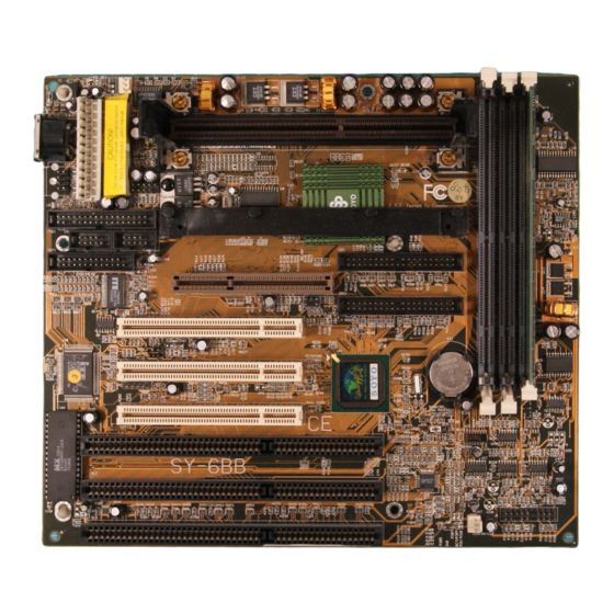
Page 4: Sy-6Bb Motherboard Layout
Motherboard Layout SY-6BB SY-6BB MOTHERBOARD LAYOUT PS/2 Mouse Connector Connector Flash BIOS ITE8671 AT Power ATX Power PRT 1 CPUFAN JP50 COM 1 COM 2 AGP Slot JP44 Slot 1 for PCI Slot #3 ® Pentium II Processor PCI Slot #2... -
Page 5: Motherboard Features
Motherboard Features & Default Settings SY-6BB MOTHERBOARD FEATURES Board Size 4-layer PCB, 22.x25. cm, AT Form Factor ® Slot 1 Slot 1 for Pentium II Processor; supports: Ø ® Pentium II Processors up to 100 MHz host bus frequency (233-550MHz) Ø... -
Page 6: Default Settings
Motherboard Features & Default Settings SY-6BB MOTHERBOARD FEATURES (CONTINUED) PS/2 Mouse 1 x PS/2 Mouse Connector USB1, USB2 2 x USB (Universal Serial Bus) Connectors Keylock 5-pin KeyLock Connector Reset 2-pin Reset Switch Connector Speaker 4-pin PC Speaker Connector TB_LED... -
Page 7: Quick Installation Guide
Quick Installation Guide SY-6BB QUICK INSTALLATION GUIDE Congratulations on your purchase of SY-6BB Motherboard. You are about to install and connect your motherboard. Note: Do not unpack the motherboard from its protective anti-static packaging until you have made the following preparations. -
Page 8: Installation Guide
Step 1. CPU Installation Your SY-6BB motherboard comes with a CPU retention set kit. The ® retention set is used to hold the Pentium II processor attached to the Slot 1 CPU connector on the motherboard. - Page 9 Quick Installation Guide SY-6BB Supporting Base Support Clip Latches (x2) Screws (x2) Retention Clip 2. Position the Motherboard Locate Slot 1 on the motherboard and position the board in the direction as shown in the following figure: Slot 1 ATX Power...
- Page 10 Quick Installation Guide SY-6BB 3. Insert the Screws Install the two pairs of screws used to set the retention clip in the two pairs of holes at both ends of Slot 1. Insert the screws from below the motherboard upward, as shown in the figure below.
- Page 11 Quick Installation Guide SY-6BB 5. Install the Retention Clip Set the retention clip centered on Slot 1 and right on top of the two sets of screws along side Slot 1, as shown in the following figure. Then tighten the four screws on the retention clip.
- Page 12 Quick Installation Guide SY-6BB 6. Install the CPU Insert the CPU into the retention clip and lock the two latches on the ® sides of the CPU to secure the Pentium II processor in place, as shown in the following figures.
- Page 13 Quick Installation Guide SY-6BB 7. Install the Support Clip Insert the support clip on the supporting base so that the CPU heat sink can seat on top of the supporting base, as shown in the following figure. 8. Insert the Latches...
- Page 14 Quick Installation Guide SY-6BB Step 2. CPU Fan Installation ® Your Pentium II processor kit comes with a cooling fan. Mount the fan on the processor according to the instructions provided by the manufacturer. The fan is a key component that will ensure system stability.
- Page 15 Quick Installation Guide SY-6BB Connect one side of the 40-pin flat cable to the IDE device (HDD or CD-ROM) and plug the other end to the primary [IDE1] or secondary [IDE2] directionally keyed IDE connector on the motherboard. This motherboard can support up to four HDDs.
- Page 16 Quick Installation Guide SY-6BB Plug the computer case's front panel devices to the corresponding connectors on the motherboard. 1. Power LED & KeyLock Plug the Power LED cable into the 5-pin Keylock connector. Some systems may feature a KeyLock function with a front panel switch for enabling or disabling the keyboard.
- Page 17 Quick Installation Guide SY-6BB 6. ATX Power On/Off Switch Attach the 2-pin momentary type switch to the PWRBT connector for turning On or Off your ATX power supply. Step 8. External Peripherals Connections External devices such as the keyboard, printer, PS/2 mouse, modem, USB can be connected to the motherboard.
- Page 18 Quick Installation Guide SY-6BB 1. Serial Ports COM1/COM2 External peripherals that use serial transmission scheme include serial mouse and modem. Your motherboard comes with two types of serial connectors with flat cables: Ø one 9-pin male external connector with 9-pin flat cable Ø...
- Page 19 Quick Installation Guide SY-6BB 2. Parallel Port PRT1 This parallel port is used to connect the printer or other parallel devices. Your motherboard comes with one 25-pin female external parallel connector with 25-pin flat cable. Plug the 25-pin end of the flat cable into the PRT1 parallel connector on the motherboard, as shown in the figure below, then fix the external 25-pin connector to the rear panel of the computer case.
- Page 20 Quick Installation Guide SY-6BB 3. PS/2 Keyboard Plug the keyboard jack directly into the 6-pin female PS/2 keyboard connector located at the rear panel of the motherboard. PS/2 Keyboard Connector 4. PS/2 Mouse Attach the mouse cable to the 6-pin male PS/2 mouse connector on the motherboard to enable PS/2 mouse function.
- Page 21 Quick Installation Guide SY-6BB Step 9. Other Connections 1. Wake-On-LAN (WOL) Attach the 3-pin connector from the LAN card which supports the Wake-On-LAN (WOL) function to the JP44 connector on the motherboard. This WOL function lets users wake up the connected computer through the LAN card.
- Page 22 Quick Installation Guide SY-6BB Step 10. Cooling Fan Installation 1. CPU Cooling Fan After you have seated the CPU properly on the processor, attach the 3-pin fan cable to the CPUFAN connector on the motherboard. The fan will stop when the system enters into Suspend Mode. (Suspend mode can be enabled from the BIOS Setup Utility.)
-
Page 23: Atx Power
Quick Installation Guide SY-6BB Step 11. AGP VGA Card Insert the AGP VGA card into the AGP slot. Then connect the monitor information cable to the AGP card back plane external connector. Follow the manufacturer's instructions to perform the AGP VGA drivers installation. - Page 24 Quick Installation Guide SY-6BB Warning: Follow these precautions to preserve your motherboard from any remnant currents when connecting to ATX power supply: Turn off the power supply and unplug the power cord of the ATX power supply before connecting to ATX PW connector.
- Page 25 Quick Installation Guide SY-6BB Step 14. AT Power Supply If you are using AT power, plug the dual 6-pin headers from the power directly into the 12-pin male AT Power connector on the motherboard. Make sure the black leads of the 6-pin AT power headers are in the center.
- Page 26 Time, Date, Hard Disk Type… You are now ready to configure your system with the BIOS setup program. Go to Chapter 3: BIOS SETUP Or continue to Chapter1: INTRODUCTION and Chapter2: HARDWARE SETUP for more information about your SY-6BB Motherboard.
-
Page 27: Chapter 1 Introduction
Introduction SY-6BB Chapter 1 INTRODUCTION The SY-6BB AGP Set motherboard is a high-performance ® Pentium II processor supported AT form-factor system board. SY- ® 6BB uses the 82440 BX Chipset technology and supports Pentium II series processors. This motherboard is fully compatible with industry standards and adds many technical enhancements. - Page 28 Introduction SY-6BB BUS Controller Ø Compliant with v2.1 PCI specifications Ø Features 3 x 32-bit PCI slots: 3 x Bus Mastering PCI Slots Ø Features 3 x 16-bit ISA slots Ø Features 1 x 32-bit AGP slot Ø Provides on-board USB (Universal Serial Bus) port Peripheral Controller Ø...
-
Page 29: Unpacking The Motherboard
Introduction SY-6BB 1-2 UNPACKING THE MOTHERBOARD When unpacking the motherboard, check for the following items: Ø The SY-6BB 82440 BX AGP Set Motherboard Ø This Quick Start Guide Ø The Installation CD-ROM Ø The CPU Retention Set Ø One IDE Device Flat Cable Ø... -
Page 30: Electrostatic Discharge Precautions
Introduction SY-6BB 1-4 ELECTROSTATIC DISCHARGE PRECAUTIONS Make sure to ground yourself before handling the motherboard or other system components. Electrostatic discharge can easily damage the components. Note that you must take special precautions when handling the mainboard in dry or air-conditioned environment. -
Page 31: Chapter 2 Hardware Setup
Hardware Setup SY-6BB Chapter 2 HARDWARE SETUP In addition to the Installation Guide, this section is designed to help you configure the motherboard hardware and to provide complementary knowledge of the hardware. (This chapter is designed for Normal edition motherboard use only.) -
Page 32: Power-On By Keyboard Function Jumper Jp5029
Hardware Setup SY-6BB 2-2 Power-On by Keyboard Function Jumper JP50 Enable the Wake-Up by Keyboard function by Shorting pin 2-3 on jumper JP50, otherwise, short pin 1-2 to disable this function. Jumper JP50 can be easily identified by its red color cap. -
Page 33: Cpu Type Configuration
Hardware Setup SY-6BB 2-4 CPU Type Configuration This motherboard does not use any jumpers to set the CPU frequency, CPU settings are changed through the BIOS Setup Utility. Enter the BIOS Setup Utility [CHIPSET FEATURES SETUP] section and configure the CPU frequency settings to match the working ®... -
Page 34: Hardware Setup
Hardware Setup SY-6BB CPU Settings in BIOS ROM PCI/ISA BIOS CHIPSET FEATURES SETUP AWARD SOFTWARE, INC. Auto Configuration : Enabled CPU Speed : 133MHz (66 x 2) SDRAM CAS latency Time DRAM Data Integrity Mode : Non-ECC System BIOS Cacheable... -
Page 35: Memory Configuration
Hardware Setup SY-6BB 2-5 MEMORY CONFIGURATION This motherboard features 3 x DIMM Banks for 168-pin 3.3V unbuffered DIMM modules Your board comes with four DIMM sockets, providing support for up to 384MB of main memory using DIMM modules from 8MB to 128MB. -
Page 36: Multi I/O Addresses
Hardware Setup SY-6BB 2-6 MULTI I/O ADDRESSES Default settings for multi-I/O addresses are as follows: Port I/O Address Status LPT1 378H ECP/EPP COM1 3F8H COM2 2F8H Warning: If a default I/O address conflicts with other I/O cards such as sound card, you must change one of the I/O addresses to remedy to this address conflict. -
Page 37: Chapter 3 Bios Setup Utility
BIOS Setup Utility SY-6BB Chapter 3 BIOS SETUP UTILITY This motherboard's BIOS setup program uses the ROM PCI/ISA BIOS program from Award Software Inc. To enter the Award BIOS program's Main Menu: 1. Turn on or reboot the system. 2. After the diagnostic checks, press the [Del] key to enter the Award BIOS Setup Utility. -
Page 38: Save And Exit Setup
BIOS Setup Utility SY-6BB Hot Keys: Function keys give you access to a group of commands throughout the BIOS utility. Function Command Description Help Gives the list of options available for each item. Color Change the color of the display window. -
Page 39: Standard Cmos Setup
BIOS Setup Utility SY-6BB 3-1 STANDARD CMOS SETUP Select the [STANDARD CMOS SETUP] option from the Main Menu and press [Enter] key. ROM PCI/ISA BIOS STANDARD CMOS SETUP AWARD SOFTWARE, INC. Date (mm:dd:yy) : Fri, Feb 1 1995 Time (hh:mm:ss) - Page 40 BIOS Setup Utility SY-6BB 3-1.2 Hard Disks Type & Mode Choose the type and mode for the hard disks that you have already installed. Primary Setting Description Note (Secondary) Master & Slave Type Auto BIOS detects hard disk type Default automatically.
- Page 41 BIOS Setup Utility SY-6BB 3-1.4 Video Select the video mode: EGA/VGA (Default), CGA 40×25, CGA 80×25, Mono (Monochrome). 3-1.5 Halt On When the BIOS detects system errors, this function will stop the system. Select which type of error will cause the system halt: All Errors (Default), No Errors, All But Diskette, All But Keyboard, All But Disk/Key.
-
Page 42: Bios Features Setup
BIOS Setup Utility SY-6BB 3-2 BIOS FEATURES SETUP Select the [BIOS FEATURES SETUP] option from the Main Menu and press [Enter] key. ROM PCI/ISA BIOS BIOS FEATURES SETUP AWARD SOFTWARE, INC. Virus Warning : Disabled Video BIOS Shadow : Enabled... - Page 43 BIOS Setup Utility SY-6BB 3-2.1 Virus Warning Setting Description Note Virus Warning Disabled Default Enabled Enable this option to protect the boot sectors and partition tables of your hard disk. Any attempt to write to them will the system to halt and display a warning message.
- Page 44 BIOS Setup Utility SY-6BB 3-2.3 System Boot Control Settings System Boot Setting Description Note Control Settings Quick Power On Disabled Self Test Enabled Provides a fast POTS at Default boot-up. Boot Sequence A, C, SCSI Choose the boot sequence adapted to...
- Page 45 BIOS Setup Utility SY-6BB 3-2.4 Typematic Settings Typematic Setting Description Note Settings Typematic Disabled Default Rate Setting Enabled Enable to adjust the keystroke repeat rate. Typematic Rate Char / sec Choose the rate a character keeps repeating. Typematic Delay Msec...
- Page 46 BIOS Setup Utility SY-6BB Other Control Options (continued) Other Control Setting Description Note Options Assign IRQ Disabled Default For VGA Enabled When using a video card that requies an IRQ. OS Select for When using an OS2 DRAM>64MB operating system.
-
Page 47: Chipset Features Setup
BIOS Setup Utility SY-6BB 3-3 CHIPSET FEATURES SETUP Caution: Change these settings only if you are already familiar with the Chipset. The [CHIPSET FEATURES SETUP] option changes the values of the chipset registers. These registers control the system options in the computer. - Page 48 BIOS Setup Utility SY-6BB CHIPSET FEATURES SETUP CHIPSET Setting Description Note FEATURES Auto Enabled It is strongly recommended Default Configuration to enable this option so that the system automatically sets all options on the left panel of the screen (except for cache update &...
- Page 49 BIOS Setup Utility SY-6BB CHIPSET FEATURES SETUP (Continued) CHIPSET Setting Description Note FEATURES Passive Release Enabled Use the default setting Default Delayed Enabled Use the default setting Default Transaction AGP Aperture 4MB- AGP could use the DRAM Size 256MB as its video RAM. Choose...
- Page 50 BIOS Setup Utility SY-6BB CHIPSET FEATURES SETUP (Continued) CHIPSET Setting Description Note FEATURES If [CPU Speed] is set to [Manual] CPU Host Clock Select the host clock of your 66 MHz ® Select Pentium II processor among these 68 MHz values.
- Page 51 BIOS Setup Utility SY-6BB CHIPSET FEATURES SETUP (Continued) CHIPSET Setting Description Note FEATURES Current CPUFAN Show the current status of °C/°F Speed CPU Fan Current CHSFAN Show the current status of °C/°F Speed CHS Fan VID, VTT, 3.3V, Show the current voltage +12V, -5V, +5V, status.
-
Page 52: Power Management Setup
BIOS Setup Utility SY-6BB 3-4 POWER MANAGEMENT SETUP The [POWER MANAGEMENT SETUP] sets the system's power saving functions. ROM PCI/ISA BIOS POWER MANAGEMENT SETUP AWARD SOFTWARE, INC. ACPI function : Disabled ** Reload Global Timer Events ** Power Management : User Define... - Page 53 BIOS Setup Utility SY-6BB 3-4.1 Power Management Controls Power Setting Description Note Management Controls ACPI Disabled Default function Enabled ACPI (Advanced Configuration Power Management Interface) Power User Define Lets you define the HDD and Default Management system power down times.
- Page 54 BIOS Setup Utility SY-6BB 3-4.2 PM Timers PM Timers Setting Description Note Doze Mode Disabled Default 1Min- When the set time has System clock 1Hour elapsed, BIOS sends a drops to command to the system to 33MHz. enter Doze Mode.
- Page 55 BIOS Setup Utility SY-6BB PM Events (continued) PM Events Setting Description Note CPUFAN Off Disabled Disables the PM timer. In Suspend Enabled Switches off the CPU Fan Default when the system enters Suspend Mode. Resume by Disabled Default Ring Enabled The system will resume active when the modem is ringing.
-
Page 56: Pnp/Pci Configuration Setup
BIOS Setup Utility SY-6BB 3-5 PNP/PCI CONFIGURATION SETUP This option sets the motherboard's PCI Slots. ROM PCI/ISA BIOS PNP/PCI CONFIGURATION AWARD SOFTWARE, INC. Used MEM base addr : N/A PnP OS Installed : No Resources Controlled By : Manual Assign IRQ For USB... - Page 57 BIOS Setup Utility SY-6BB 3-5.1 PNP/PCI Configuration Controls PNP/PCI Setting Description Note Controls PnP OS Set this field to [Yes] if Installed you are running Windows 95, which is PnP compatible. If the OS you are Default (If there is any...
- Page 58 BIOS Setup Utility SY-6BB 3-5.2 PNP/PCI Configuration Setup PNP/PCI Setting Description Note Setup If [Resources Controlled By] is set to [Manual] IRQ-3,4,5,7,9,10, IRQ-# and PCI/ISA PnP Choose IRQ-# and 11,12,14,15 DMA-# DMA-# assigned to DMA-0,1,3,5,6,7 assigned to: PCI/ISA PnP card.
-
Page 59: Load Setup Defaults
BIOS Setup Utility SY-6BB 3-6 LOAD SETUP DEFAULTS Select the [LOAD SETUP DEFAULTS] option from the Main Menu to load the system values you have previously saved. This option is recommended if you need to reset the system setup and to retrieve the old values. -
Page 60: Integrated Peripherals
BIOS Setup Utility SY-6BB 3-8 INTEGRATED PERIPHERALS Caution: Change these settings only if you are already familiar with the Chipset. The [INTEGRATED PERIPHERALS] option changes the values of the chipset registers. These registers control the system options in the computer. - Page 61 BIOS Setup Utility SY-6BB 3-8.1 IDE Device Controls IDE Controls Setting Description Note IDE HDD Block Mode Disabled Enabled Invokes multi-sector Default transfer instead of one sector per transfer. Not all HDDs support this function. mode 0 is the slowest speed Ø...
- Page 62 BIOS Setup Utility SY-6BB 3-8.2 Keyboard Controls Keyboard Setting Description Note Controls USB Keyboard Disabled Turn off the on-board Default Support Enabled Use a USB keyboard Init AGP Display Disabled Default First Enabled If you choose to initialize the AGP...
- Page 63 BIOS Setup Utility SY-6BB 3-8.3 FDC Controls FDC Controls Setting Description Note Onboard FDC controller Disabled Turn off the on-board floppy controller Enabled Use the on-board Default floppy controller 3-8.4 Onboard Serial Ports Onboard Serial Setting Description Note Ports Onboard PORT 1...
- Page 64 BIOS Setup Utility SY-6BB 3-8.5 Onboard Parallel Ports Onboard Parallel Setting Description Note Ports Onboard Parallel Disabled Choose the printer I/O Port address. 378/IRQ7 Default 3BC/IRQ7 278/IRQ5 Parallel Port Mode ECP+EPP The mode depends on Default your external device that connects to this port.
-
Page 65: Supervisor Password
BIOS Setup Utility SY-6BB 3-9 SUPERVISOR PASSWORD Based on the setting you have made in the [Security Option] of the [BIOS FEATURES SETUP] section, the password prevents access to the system or the setup program by unauthorized users. Follow this procedure to set a new password or disable the password: Choose [BIOS FEATURES SETUP] in the Main Menu and press [Enter]. -
Page 66: User Password
BIOS Setup Utility SY-6BB Enter your new password and press [Enter]. The following message appears, prompting to confirm the new password: Re-enter your password and then press [Enter] to exit to the Main Menu. This diagram outlines the password selection procedure: ↔... -
Page 67: Ide Hdd Auto Detection
BIOS Setup Utility SY-6BB 3-11 IDE HDD AUTO DETECTION This Main Menu function automatically detects the hard disk type and configures the STANDARD CMOS SETUP accordingly. ROM PCI/ISA BIOS CMOS SETUP UTILITY AWARD SOFTWARE, INC. HARD DISKS TYPE SIZE CYLS HEAD... -
Page 68: Appendix Quick Start Guide
This guide is designed for those users who have prior knowledge of motherboard operations and are already familiar with basic motherboard settings. For further information, please refer to SY-6BB Motherboard User's Guide and Technical Reference online manual included on the CD-ROM packed with your motherboard. -
Page 69: Jumper Settings And Connectors
SY-6BB Appendix: Quick Start Guide Jumper Settings and Connectors CMOS Clear: Power On by PCI Audio Card Connector: SB-Link ™ Keyboard: JP50 CPU Cooling Fan: CPUFAN Retain 5VSB Some PCI audio cards needs a DMA Chassis Fan: CHAFAN CMOS data Support channel. - Page 70 Appendix: Quick Start Guide...
Need help?
Do you have a question about the SY-6BB and is the answer not in the manual?
Questions and answers