
Related Manuals for Sam4s ER-420


Summary of Contents for Sam4s ER-420
- Page 1 ELECTRONIC CASH REGISTER ER-420 / ER-420M / ER-420F SERVICE Manual ELECTRONIC CASH REGISTER C O N T E N T S Precaution Statements Product Specifications Installation and Operation Disassembly and Assembly Maintenance and Adjustment Exploded Views and Parts List PCB Layout and Parts List...
- Page 3 About this Manual This service manual describes how to perform hardware service maintenance for the SAM4S ER-420 Series Electronic Cash Register. Notes Notes may appear anywhere in the manual. They describe additional information about the item. Precaution symbols . Indicates a Safety Precaution that applies to this part component.
- Page 4 This manual may not, in whole or in part, be copied, photocopied, reproduced, translated or converted to any electronic or machine readable from without prior written permission of Shin Heung Precision . SAM4S ER-420M/F SERIES Service Manual First Edition. May 2004. V1.0 Printed in KOREA...
- Page 5 Overview of this ECR This service manual provides the technical information for many individual component systems, circuits and gives an analysis of the operations performed by the circuits. If you need more technical information, please contact our service branch or R&D center. Schematics and specifications provide the needed information for the accurate troubleshooting.
-
Page 6: Safety Precautions
Remplacer uniquement avec une batterie du même type recommended by the manufacturer. ou d’un type équivalent recommandé par le constructeur. Dispose used batteries according to the manufacturer’s Mettre au rebut les batteries usagées conformément aux instructions. instructions du fabricant. SAM4S ER-420M/F SERIES... - Page 7 5. Use only a grounded-tip soldering iron when soldering or unsoldering ESDs. 6. Use only an anti-static solder removal device. Many solder removal devices are not rated as anti-static; these can accumulate sufficient electrical charge to damage ESDs. SAM4S ER-420M/F SERIES...
-
Page 8: Product Specifications
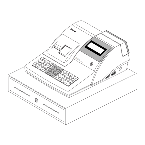
• Approx. 25W (Regularity) Power Requirement • AC 120V 60Hz, 230V 50Hz Environment • Temperature : 0℃ ~ 45℃ Condition • humidity : 30% ~ 80% RH Dimensions(mm) 400(W) x 450(D) x 266(H) ; with Drawer Table2-1 General Specification SAM4S ER-420M/F SERIES... - Page 9 2-2 B. Location Feature ① Printer Cover ② Key Board ③ Drawer ④ Customer 10-Digits VFD Display ⑤ Operator Display (16*2 Character LCD or 10-Digits VFD) ⑥ RS-232 Serial I/F Connector ⑦ Mode Key Figure2-2 Location Feature SAM4S ER-420M/F SERIES...
- Page 10 • Thermistor Head Temperature Sensor • Reflecting Photo Sensor Paper-End Sensor 2pcs • 15,000,000 Lines Life Reliability • 37,000,000 Line MCBF •131.8(W) ×174.2 (D) ×135.7 (H) Dimension (mm) • Approx. 408.0 g Weight Table2-2 Thermal Printer Specification SAM4S ER-420M/F SERIES...
- Page 11 Table2-3 Paper Specification Note: The Following paper can be used instead of the specified paper above. TF50 KS-E : Nippon Paper industries Co.Ltd. PD 160R : NEW Oji Paper Mfg, Co.Ltd F380 : Kansaki Specialty Papers, Inc.(USA) SAM4S ER-420M/F SERIES...
- Page 12 : AC 230V, 50Hz,0.16A (Min : 195.5V, Max : 264.5V) • Operating Power Consumption : 25W • AC 19V 2.3A (Wire Color : Blue-Blue) Power Transformer Output Voltage Output • AC 24V 0.15A (Wire Color : Red-Red) Table2-10 Power Specification SAM4S ER-420M/F SERIES...
- Page 13 • VCC(+5V/200mA) is supplied at 9Pin of D-SUB Connector. Voltage Supply or other devices Table2-11 RS-232C Specification 2-5 A-(b) Cable Connection & ) Figure2-4 RS232C Cable Connection (9Pin to 9Pin) & ) Figure2-5 RS232C Cable Connection (9Pin to 25Pin) SAM4S ER-420M/F SERIES...
- Page 14 Then the host recognizes that the ECR is busy. So, the host does not transmit a data to the ECR. If the ECR is released from busy, the ECR transmits XON(ASCII 11h) to host through the Serial Data Line. Then the host recognizes that the ECR is not busy. And the host transmits a data to the ECR. SAM4S ER-420M/F SERIES...
- Page 15 2 Product Specifications 2-5 B. EKLZ Interface 2-5 B-(a) Cable Connection EKLZ Signal Pin No Wire Color Pin No Signal YELLOW GREEN BLACK Table2-13 EKLZ Cable Connection 2-5 B-(b) I/F Cable Figure2-7 I/F Cable SAM4S ER-420M/F SERIES...
-
Page 16: Installation And Operation
3 Installation and Operation 3-1 System Configuration Figure 3-1 System Configuration SAM4S ER-420M/F SERIES... - Page 17 10. Place the Spool Winding on the Paper Supply. If it loosen, turn to tighten it.(Figure 3-2-8) 11. Close the PRINTER COVER. (Figure 3-2-1) (Figure3-2-2) (Figure3-2-3) (Figure3-2-4) (Figure 3-2-5) (Figure3-2-6) (Figure3-2-7) (Figure3-2-8) Figure 3-2 Paper & Spool Installation SAM4S ER-420M/F SERIES...
- Page 18 SRAM 4MBITs (4MBITs * 1) On Main PBA Table 3-1 Option 3-2 D. Supplies Item Description Remark Paper Roll 2 EA Mode Key VD, REG, X, Z, P, C User Manual 1 EA Spool 1 EA Table 3-2 Supplies SAM4S ER-420M/F SERIES...
- Page 19 Off, Register, Manager, Clear Totals Void, Off, Register, Manager, Clear Totals, Program Void, Off, Register, Manager, Clear Totals, Program, Service Mode Table3-4 Key Function Note : The Key can be removed from the key lock in the OFF or REGISTER position. SAM4S ER-420M/F SERIES...
- Page 20 INITIAL CLEAR OK! = = = = = = = = = = = = = = = = = = = = = = = CLERK 00 No.000036 0000 Figure3-6 Initial Clear Key & Print Sheet SAM4S ER-420M/F SERIES...
- Page 21 JANUARY 31 2004 = = = = = = = = = = = = = = = = = = = = = = = CLERK 00 No.000001 00000 Figure3-7 All Clear Key Sequence & Print Sheet SAM4S ER-420M/F SERIES...
- Page 22 2. Press Press ‘2’, ‘4’ and ‘SBTL’ key on key board. 3. If error occurs, the message (232 NOGOOD) is displayed on VFD and the Buzzer beep. Then Press “Clear” key. Note : When the ports is unconnected with the cable , the Error occur. SAM4S ER-420M/F SERIES...
- Page 23 3 Installation and Operation MEMO SAM4S ER-420M/F SERIES...
-
Page 24: Disassembly And Assembly
2. Remove the two screws(B-5) on the ASS'Y COVER MODE S/W(B-2) and separate the MODE KEY ASS’Y(B-7) from the PMO-COVER MODE S/W(B-2). (Page9-4, 9-5) 3. Remove the two screws(B-3) on the MODE KEY ASS’Y(B-7) and separate the IPR-BRKT MODE S/W(B-4) and the MODE KEY ASS’Y(B-7). (Page9-4, 9-5) SAM4S ER-420M/F SERIES... - Page 25 3. Separate the harnesses(ⓖ,ⓩ) and Remove the two screws(E-11). (page9-11) 4. Lift up the PBA SUB POWER SW(E-12) from the IPR-BRKT TRANS(E-21).(page9-11) 5. Remove the eight screws(E-13:2PCS, E-14:1PCS, E-15:2PCS, E-17:3PCS) and Separate the IPR-BRKT TRANS(E-21) from the PMO-CASE LOWER(E-18).(page9-11) SAM4S ER-420M/F SERIES...
-
Page 26: Maintenance And Adjustment
Use in places where the products are exposed to sea winds or corrosive gases, including CL S, SO and NO d. Use in places where the products are exposed to static electricity or electromagnetic waves e. Use of the products in places subject to dew condensation. SAM4S ER-420M/F SERIES... - Page 27 5 Maintenance and Adjustment MEMO SAM4S ER-420M/F SERIES...
- Page 28 6. Exploded Views and Parts List 6-1. Exploded View(ER-420M) Figure 6-1 Total Disassembly (ER-420M) SAM4S ER-420M/F SERIES...
- Page 29 6 Exploded Views and Parts List 6-1. Exploded View(ER-420F) Figure 6-2 Total Disassembly (ER-420F) SAM4S ER-420M/F SERIES...
- Page 30 6 Exploded Views and Parts List 6-2 A. ASS’Y COVER-PRINTER Figure 6-3 ASS’Y COVER-PRINTER A. ASS’Y COVER-PRINTER Parts No. Description / Specification Q`ty Design-Location Serviceable Remark JK97-20017A MEA-COVER PRINTER JK72-20087A PMO-WINDOW JOURNAL JK72-20086A PMO-COVER PRINTER JK70-20021A IPR-CUTTER PAPER JK70-50012A SCREW-TAPPING;PH,+,M2.6,L6 SAM4S ER-420M/F SERIES...
- Page 31 PMO-WINDOW TURRET JK92-00970B PBA SUB-TURRET B-10 JK72-00015A PMO-TURRET BODY B-11 6001-000367 SCREW-MACHINE: FH,+,M4,L10 B-12 JK72-00012C PMO-CASE UPPER:ER-420M B-13 JK72-20110A PMO-HOLDER DISPLAY B-14 6002-000175 SCREW-TAPPING: PWH,+,2,M3,L8,ZPC(YEL) B-15 JK96-01080E LCD ASS’Y:16CHAR*2LINE B-16 6002-000175 SCREW-TAPPING: PWH,+,2,M3,L8,ZPC(YEL) B-17 JK72-20065A PMO-WINDOW DISPLAY,LCD SAM4S ER-420M/F SERIES...
- Page 32 PBA TURRET B-10 JK72-00015A PMO-TURRET BODY B-11 6001-000367 SCREW-MACHINE: FH,+,M4,L10 B-12 JK70-40305A ICT-SHAFT MOLDING B-13 JK72-00012D PMO-CASE UPPER:ER-420F,STD B-14 JK70-10407A IPR-BRKT WINDOW_PCB B-15 6002-000175 SCREW-TAPPING: PWH,+,2,M3,L8,ZPC(YEL) B-16 JK92-01242A PBA SUB B-17 6002-000175 SCREW-TAPPING: PWH,+,2,M3,L8,ZPC(YEL) B-18 JK39-40600A HARNESS-DISPLAY:350mm SAM4S ER-420M/F SERIES...
-
Page 33: Exploded Views And Parts List
C-5-3-3 C-5-3-4 C-5-4 C-5-17 C-5-3-5 C-5-3 C-5-9 C-5-5 C-5-10 C-5-6 C-5-7 C-5-11 C-5-13 C-5-12 C-5-8 C-5-14 C-5-9 C-5-11 C-5-10 C-5-19 C-5-22-1 C-5-20 C-5-12 C-5-22 C-5-15 C-5-21 C-5-16 C-5-22-2 C-5-14 C-5-18 C-5-23 C-5-22-3 C-5-24 Figure 6-6 ASS’Y PRINTER(STM-320) SAM4S ER-420M/F SERIES... - Page 34 6 Exploded Views and Parts List Figure 6-7 Lubrication Points of the Printer (STM-320) SAM4S ER-420M/F SERIES...
- Page 35 PBA SUB-CONNECTION BOARD C-5-21 JK70-50025A SCREW-TAPPING;PWH,+,M2.6,L6,ZPC C-5-22 JK97-20023A ASSY TPH;STM-320 C-5-22-1 JK47-10002A THERMAL PRINT HEAD C-5-22-2 JK72-20069A PMO-COVER TOP:STM-320 C-5-22-3 JK70-50009A SCREW-MACHINE:RH,+,M2,L4 C-5-23 JK59-40003A UNIT-MOTOR ASSY:STM-320 C-5-24 JK72-20075A PMO-HOLDER PRINTER:STM-320 JK39-40611A HARNESS-GND: 200mm,CORE JK39-40632A HARNESS-CONNECTION;STM-320,16P JK39-00012A CBF-HARNESS-KEY OPTION SAM4S ER-420M/F SERIES...
- Page 36 6 Exploded Views and Parts List D. ASS’Y KBD(48KEY RAISED) Figure 6-8 ASS’Y-KEYBOARD (48 Key) SAM4S ER-420M/F SERIES...
- Page 37 6-2. D. ASS’Y KBD(48KEY RAISED) Parts No. Description / Specification Q`ty Design-Location Serviceable Remark JK59-30015A UNIT-KEYBOARD:ER-420,ENGLISH,48K,MEM JK81-10945A KEY-CAP(S): 1X1 LABEL-KEY TOP SET: ER-420 JK81-20013A KEY-TOP ASS'Y(S): 1X1 JK81-10285T SPRING RETURN: 1X1 JK81-10946A KEY-CAP(L): 1X2 JK81-20014A KEY-TOP ASS'Y(L): 1X2 JK81-20001A SPRING-RETURN: 1X2...
- Page 38 6 Exploded Views and Parts List 6-2 E. ASS’Y CASE-LOWER E-26 Figure 6-9 ASS’Y CASE-LOWER SAM4S ER-420M/F SERIES 6-11...
- Page 39 PBA MAIN-1M,FISICAL: 1M BYTE FISCAL JK92-00132C PBA SUB FISCAL B/D: 2M BYTE FISCAL JK92-01264B PBA MAIN BOARD:ER-420MF JK92-01264C PBA MAIN BOARD:ER-420M JK92-01264D PBA MAIN BOARD:ER-420 JK92-01264E PBA MAIN BOARD:ER-420F 6006-000199 SCREW-ASS’Y TAPT:WT,BH,+,M4,L8,ZPC(YEL) JK26-30511A TRANS-POWER:USA: 120V 60Hz E-10 JK26-00014A TRANS-POWER:EUROPE: 230V 50Hz...
- Page 40 ASS'Y HOUSING d. ASS'Y LOCK b. ASS'Y TRAY-TILL e. ASS'Y BOTTOM Figure 6-11 ASS’Y-DRAWER (5B/5C) a. ASS'Y BILL-COIN (7B8C) c. ASS'Y HOUSING d. ASS'Y LOCK b. ASS'Y TRAY-TILL e. ASS'Y BOTTOM Figure 6-12 ASS’Y-DRAWER (7B/8C) SAM4S ER-420M/F SERIES 6-13...
- Page 41 MEA-TRAY TILL: A-TYPE,5B5C JK73-10203A RPR-TENSION: DRAWER JK75-10386A MEC-ROLLER: DRAWER,DR-10-B1/ Φ19 6031-000549 WASHER-PLAIN: IDΦ6.5,ODΦ13, T1.0 6003-000221 SCREW-TAPTITE: PWH,+2,M4,L8,ZPC(YEL) JK70-10324A IPR-SUPPORT TRAY: DRAWER JK70-40302A ICT,SHAFT PIN: A-TYPE b-10 6044-000124 RING-E: IDΦ3,ODΦ7, T0.6,ZPC(BLK),STSC b-11 6002-001042 SCREW-TAPPING: FH,+2,M3,L6 b-12 JK70-10323A IPR-PLATE CLIP 6-14 SAM4S ER-420M/F SERIES...
- Page 42 MEA-UNIT BOTTOM: A-TYPE JK97-01076B MEA-UNIT BOTTOM: A-TYPE,UNIVERSAL JK70-10938A IPR-PLATE BOTTOM: A-TYPE JK73-40200A RMO-STOPPER: DRAWER JK73-10902A RMO-STOPPER: DRAWER,UNIVERSAL JK61-40200A RMO-FOOT RUBBER: DRAWER 6002-000234 SCREW-TAPPING: TH,+2,M4,L16,ZPC(YEL) 6003-000267 SCREW-TAPTITE: PWH,+2,M3,L8,ZPC(YEL) 6003-000267 SCREW-TAPTITE: PWH,+2,M3,L8,ZPC(YEL) JK70-10401A IPR-PLATE SPRING: DRAWER 6003-000267 SCREW-TAPTITE: PWH,+2,M3,L8,ZPC(YEL) SAM4S ER-420M/F SERIES 6-15...
- Page 43 6 Exploded Views and Parts List MEMO 6-16 SAM4S ER-420M/F SERIES...
- Page 44 7 PCB Layout and Parts List 7-1 Main PCB Layout SAM4S ER-420M/F SERIES...
- Page 45 7 PCB Layout and Parts List Part-No Description / Specification Q’TY Design Location Serviceable Remarks JK92-01264B PBA MAIN-BD:ER-420,LCD,FISCAL(LPP2) 0202-000216 SOLDER-BAR:S63S-B20,S63S,350X34,SN63/PB3 0202-001025 SOLDER-WIRE FLUX:KS-611,-,-,-,spray 0204-000469 THINNER:#4662,-,0.795,- 0201-000008 ADHESIVE-HM:#3748,WHT,6500CPS,V2 L1,L4,X1,X2 0402-000168 DIODE-RECTIFIER:1N5822,40V,3A,DO-201AD,T 0402-000168 DIODE-RECTIFIER:1N5822,40V,3A,DO-201AD,T 0402-000290 DIODE-BRIDGE:KBU6B,100V,6A,-,BK 0403-000141 DIODE-ZENER:1N4735A,6.2V,5%,1W,DO-41,TP 0501-000294 TR-SMALL SIGNAL:KSA708-Y,PNP,800mW,TO-92 Q6,Q7,Q8...
- Page 46 SCREW-TAPPING:PWH,+,2,M3,L8,ZPC(YEL) 6203-000107 HEAT SINK:NONE,T2,W17,L22,H45,DEGRE,AL60 HS1(Q4) 6203-000107 HEAT SINK:NONE,T2,W17,L22,H45,DEGRE,AL60 HS2(Q5) JC68-10564A LABEL(P)-PROTECTOR:SLB-3108H,ART,-,100(S U24(EPROM) JK27-60100D COIL FILTER:ER-350,140 UH,-,- JK27-60100D COIL FILTER:ER-350,140 UH,-,- JK94-01139B PHANTOM AU JK92-01264B(ER-420,LPP2) 0201-001235 ADHESIVE-TS:DEH-390D,RED,400,- 0202-000108 SOLDER-CREAM:RMA-010 T-322,S63,-,- D9,D15,D18,D19,D20,D21,D2 0401-001003 DIODE-SWITCHING:MMBD6050LT1,70V,200mA,22 2D23,D24,D25,D26,D27,D28 ER420F ONLY 0402-001189 DIODE-RECTIFIER:M4,400V,1A,SMD-2,TP D1,D2,D3,D4,D6,D8 D13 0404-001051...
- Page 47 C91,C93,C94,C95,C96 C97,C98,C100,C101 C102,C103 C36,C55,C58,C64,C65 2203-000239 C-CERAMIC,CHIP:0.1nF,5%,50V,NP0,TP,2012 C66,C71,C76,C77,C78 C80,C81 2203-000260 C-CERAMIC,CHIP:10nF,10%,50V,X7R,TP,2012 C73,C75 2203-000595 C-CERAMIC,CHIP:0.22nF,5%,50V,NP0,TP,2012 2203-000634 C-CERAMIC,CHIP:0.022nF,5%,50V,NP0,TP,201 C52,C56 C3,C4,C6,C9,C13,C15 2203-000938 C-CERAMIC,CHIP:0.47nF,5%,50V,NP0,TP,2012 C18,C19,C20,C23,C25, C28 C8,C11,C12,C16,C17 C22,C26,C27,C29,C30 2203-000990 C-CERAMIC,CHIP:1uF,+80-20%,25V,Y5V,TP,20 C33,C34,C35,C37,C38 C104 C46,C47,C48,C49,C67 2203-000991 C-CERAMIC,CHIP:0.82nF,5%,50V,NP0,TP,2012 C68,C69,C70 3301-000317 CORE-FERRITE BEAD:AB,2x1.25x0.9mm,-,- L5,L6,L7,L8,L9 JK41-10566A PCB-MAIN:ER-420,FR-4,2L,T1.6mm SAM4S ER-420M/F SERIES...
- Page 48 Description / Specification Q’TY Design Location Serviceable Remarks JK92-01265A PBA SUB-CONNECTION BOARD:STM-310/320 2401-000132 C-AL:1000uF,35V,20%,SHL35VB1000,12.5x20m 3711-004105 WAFER;BOX-HEADER,1R,4P,2.5mm,STRAIGHT 3711-004105 WAFER;BOX-HEADER,1R,4P,2.5mm,STRAIGHT 3711-002003 CONN-HEADER:16P,2R,2mm,ST,BLK,YDW200-16 3711-000840 CONNECTOR-HEADER:BOX,30P,2R,2MM,STRAIGHT 0604-000158 REFLECT-SENSOR:SG-105F,4P,STM-320 0604-000158 REFLECT-SENSOR:SG-105F,4P,STM-320 JK41-10567A PCB-CONNECTION:STM-320,FR-4,2L,T1.6mm JK39-40632A HARNESS-CONNECTION;STM-320,16P,60mm,UL10 CONN B'D~TPH JK39-00012A CBF-HARNESS-KEY OPTION:SPS-1000,UL1061,U CONN B'D~MAIN B'D SAM4S ER-420M/F SERIES...
- Page 49 7 PCB Layout and Parts List 7-3 Power Switch PCB Layout Remark Part-No Description / Specification Q’TY Design Location Serviceable 3711-000190 CONNECTOR-HEADER:1WALL,2P,1R,7.92mm,STRA 3711-000829 CONNECTOR-HEADER:BOX,2P,1R,6.2mm,STRAIGH CN1, CN2 JK41-10545B PCB-POWER SWITCH:ER-52/5500,FR-1,1L,T1.6 SAM4S ER-420M/F SERIES...
- Page 50 7-4 A. ER-420F Front Display (VFD 10Digit) Part-No Description / Specification Q’TY Design Location Serviceable Remarks 3711-004111 WAFER;BOX-HEADER,1R,8P,2.5mm,ANGLE 3711-002002 CONNECTOR-HEADER:-,22P,2R,2mm,STRAIGHT,S JK07-00005A DISPLAY VFD-DC10G:FUTABA,10-LT-50GK JK39-40600A HARNESS-DISPLAY;ER-380,8P,350mm,CORE HARNESS JK73-10207A RPR-PAD:ER-220N,SPONGE,-,BLK,- T5.0 1003-001381 IC-VFD:HV5812P,DIP,28P,540MIL,-,-,ST,PLA 0402-000208 DIODE-RECTIFIER:EK-04,40V,1.5A,DO-41 0402-000129 DIODE-RECTIFIER:1N4003,200V,1A,DO-41,TP JC39-40511A CBF HARNESS:ML-80,JUMPER,AWG22,52mm,SILV J1~J21 JK41-10005B PCB-DISPLAY(10G):ER-350/F,FR-1,1L,T1.6 SAM4S ER-420M/F SERIES...
- Page 51 PBA SUB-TURRET:ER-450,WORLD,BASIC 3711-004109 WAFER;BOX-HEADER,1R,8P,2.5mm,STRAIGHT WHITE JK07-00005A DISPLAY VFD-DC10G:FUTABA,10-LT-50GK JK39-40606A HARNESS-TURRET:ER-450,8P,500mm,TUBE TURR TO MAIN TUBE JK73-10207A RPR-PAD:ER-220N,SPONGE,-,BLK,- T5.0 1003-001381 IC-VFD:HV5812P,DIP,28P,540MIL,-,-,ST,PLA JK69-90902A PACKING-VINYL:PET,#2126,30X100000XT0.05, DIGITRON 0402-000129 DIODE-RECTIFIER:1N4003,200V,1A,DO-41,TP 0402-000208 DIODE-RECTIFIER:EK-04,40V,1.5A,DO-41 JK41-10547A PCB-TURRET:ER-650/5200,FR-1,1L,T1.6 2202-000579 C-CERAMIC,MLC-AXIAL:100nF,+80-20%,50V,Z5 C1,C2 JC39-40511A CBF HARNESS:ML-80,JUMPER,AWG22,52mm,SILV J1 ~ J9 SAM4S ER-420M/F SERIES...
- Page 52 Design Location Serviceable JK92-00132B PBA SUB-FISCAL B/D;1MBITs 1MBITs ASSY 1102-000109 IC-EPROM:27C010,128Kx8BIT,DIP,32P,600MI 0403-000141 DIODE-ZENER:1N4735A,6.2V,5%,1W,DO-41,TP ER420F ONLY JK39-40305B CBF HARNESS:,-,UL 1007,120,WHT/BLU/RED,2 2007-000029 R-CHIP:0OHM,5%,1/10W,DA,TP,2012 2007-000030 R-CHIP:560OHM,5%,1/10W,DA,TP,2012 2007-000221 R-CHIP:1.2KOHM,5%,1/10W,DA,TP,2012 2007-000872 R-CHIP:4.7KOHM,5%,1/10W,DA,TP,2012 R1,R5~R13 2203-000192 C-CERAMIC,CHIP:100nF,+80-20%,50V,Y5V,TP, 0404-001051 DIODE-SCHOTTKY:SK14,40V,1000MA,DO-214AA, D1,D2 0501-000457 TR-SMALL SIGNAL:MMBT2222A,NPN,350MW,SOT- JK41-10531B PCB-FISCAL:ER-5240F,FR-4,2L,T1.6mm,348X5 SAM4S ER-420M/F SERIES...
- Page 53 2007-000872 R-CHIP:4.7KOHM,5%,1/10W,DA,TP,2012 R1,R5~R13 2203-000192 C-CERAMIC,CHIP:100nF,+80-20%,50V,Y5V,TP, 0404-001051 DIODE-SCHOTTKY:SK14,40V,1000MA,DO-214AA, D1,D2 0501-000457 TR-SMALL SIGNAL:MMBT2222A,NPN,350MW,SOT- JK41-10531B PCB-FISCAL:ER-5240F,FR-4,2L,T1.6mm,348X5 7-6 Interface Layout Part-No Description / Specification Q’TY Design Location Serviceable Remarks JK92-01280A PBA SUB-I/F:ER-380/M,232*2 3711-002002 CONNECTOR-HEADER:-,22P,2R,2mm,STRAIGHT,S 3701-000232 CONNECTOR-DSUB:9P,2R,FEMALE,ANGLE,AUF 3701-000232 CONNECTOR-DSUB:9P,2R,FEMALE,ANGLE,AUF JK41-10571A PCB-I/F:ER-380/M,232*2,FR-4,2L,T1.6mm 7-10 SAM4S ER-420M/F SERIES...
-
Page 54: Troubleshooting
3. Check Generated Frequency 4. Check the +24V whether it is short or open. 1. Check the KA34063(U5) Power VCC 2. Check the TR KSA1010(Q5) (+5V) Ok? 3. Check the VCC whether it is short or open. SAM4S ER-420M/F SERIES... - Page 55 4. Replace the SRAM. 1. Check the nCS, nRD, nWR signal of RTC 2. Check the VBT(Battery Volt.). RTC Ok? 3. Check the Decoder IC 74HC138 (U9). 4. Check the RTC Clock 32.768KHz 5. Replace the RTC(RS5C372A) SAM4S ER-420M/F SERIES...
- Page 56 3. Check the LATCH Signal (CPU P9.7) 4. Check the Harness. 1. Check and Replace the VFD PBA. VFD PBA 2. Check the HV5812P. Assy Ok? 3. Check the VFD. 4. Check the Harness & Soldering Point. SAM4S ER-420M/F SERIES...
- Page 57 Thermistor 2. Check the related Circuit and Pattern. 3. Check the Harness. 4. Check the Thermistor of TPH. 1. Check the Control Signal on CPU 2. Check the Harness. Print 3. Check the related Circuit and Pattern. SAM4S ER-420M/F SERIES...
- Page 58 2. Check the Matrix Bus & Data Bus Failure? 3. Check the Diodes(D22~D29) 4. Check the Key Board Assy 1. Check the Harness & Mode Key Assy Mode Key 2. Check Diode (D18) 3. Check the 74HCT541 & Data Bus & CPU P10.3 SAM4S ER-420M/F SERIES...
- Page 59 2. Check the related circuit & Component KSD288 (Q1) Failure ? MMBT2222A(Q2) on Main PBA. 3. Check the Solenoid in the Drawer. 1. Check the Compulsory Harness & Connector. Compulsory 2. Check the Micro switch in the Drawer. Failure? SAM4S ER-420M/F SERIES...
- Page 60 3. Check whether Signal is affected by the Cable Noise. 1. Check the connection of the H/W handshaking Line and Other side H/W Handshake 2. Check the I/F Cable whether it is open or short. 3. Confirm the H/W handshaking Protocol. SAM4S ER-420M/F SERIES...
- Page 61 8 Troubleshooting MEMO SAM4S ER-420M/F SERIES...
-
Page 62: Block Diagram
DRIVER 74HC138 nCS(EXTIN) SSCG FS781 PEND nCS(FISCAL) BUFFER nCS(EXTIN) SENS 74HC541 nCS(KEY) 14.7456MHz D[0:7] D[0:7] nCS(FISCAL) KEY DECOD KEY BUFFER PERI 74HC138 74HC541 82C55 A[0:1] FA[0:17] FD[0:7] FISCAL B'D KEY BOARD MAX(2MBITs) 48 KEY MODE KEY SAM4S ER-420M/F SERIES... -
Page 63: Mode Key
DRIVER 74HC138 SSCG nCS(EXTIN) FS781 PEND nCS(FISCAL) BUFFER nCS(EXTIN) SENS 74HC541 nCS(KEY) 14.7456MHz D[0:7] D[0:7] nCS(FISCAL) PERI KEY DECOD KEY BUFFER A[0:1] 74HC138 74HC541 82C55 FA[0:17] FD[0:7] FISCAL B'D KEY BOARD MAX(2MBITs) 48 KEY MODE KEY SAM4S ER-420M/F SERIES... - Page 64 VDISP (+30VDC) VFD Grid/Anode Driving Voltage (+24VDC) Cash Drawer Solenoid Driving / Fiscal Writing Voltage (+5VDC) Logic IC Driving / VFD Filament Voltage (+Min 3.6VDC) Battery Voltage (Use for RTC, SRAM) Table 9-1 Power Source Voltage Descriptions SAM4S ER-420M/F SERIES...
- Page 65 9 Block Diagram MEMO SAM4S ER-420M/F SERIES...
-
Page 66: Wiring Diagram
CN14 / 15= Keyboard RECEIPT LF MOTOR OUT #A FA10 CN 3= RS-232 / CN5=LCD DISPLAY RECEIPT LF MOTOR OUT #A- FA11 CN13 = MODE KEY RECEIPT LF MOTOR OUT #B RECEIPT LF MOTOR OUT #B- SAM4S ER-420M/F SERIES 10-1... - Page 67 10 Wiring Diagram MEMO 10-2 SAM4S ER-420M/F SERIES...
-
Page 68: Schematic Diagrams
1) VFD Front Schematics(ER-420F) ----------------------------- 11-11 2) VFD Rear Schematics(ER-420F) ------------------------------ 11-12 3) VFD Rear Schematics(ER-420M)------------------------------ 11-13 4. Fiscal PCB Schematics. ------------------------------------------- 11-14 5. STM-320 Printer PCB Schematics. ----------------------------- 11-15 6. Serial Interface PCB Schematics.-------------------------------- 11-16 SAM4S ER-420M/F SERIES 11-1... - Page 69 11-1 CPU PART 11-2 SAM4S ER-420M/F SERIES...
- Page 70 11-2 MEMORY PART SAM4S ER-420M/F SERIES 11-3...
- Page 71 11-3 DISPLAY, BUZZER, FAIL PART 11-4 SAM4S ER-420M/F SERIES...
- Page 72 11-4 INTERFACE PART SAM4S ER-420M/F SERIES 11-5...
- Page 73 11-5 KEY SCAN PART 11-6 SAM4S ER-420M/F SERIES...
- Page 74 11-6 PRINTER PART SAM4S ER-420M/F SERIES 11-7...
- Page 75 11-7 FISCAL PART 11-8 SAM4S ER-420M/F SERIES...
- Page 76 11-8 POWER PART SAM4S ER-420M/F SERIES 11-9...
- Page 77 11-9 POWER S/W PCB 11-10 SAM4S ER-420M/F SERIES...
- Page 78 11-10 FRONT DISPLAY PCB (ER-420F) SAM4S ER-420M/F SERIES 11-11...
- Page 79 11-11 REAR DISPLAY PCB (ER-420F) 11-12 SAM4S ER-420M/F SERIES...
- Page 80 11-12 REAR DISPLAY PCB (ER-420M) SAM4S ER-420M/F SERIES 11-13...
- Page 81 11-13 FISCAL PCB 11-14 SAM4S ER-420M/F SERIES...
- Page 82 11-14 STM-320 PRINTER PCB SAM4S ER-420M/F SERIES 11-15...
- Page 83 11-15 SERIAL I/F PCB 11-16 SAM4S ER-420M/F SERIES...
- Page 84 Use this page to record any special servicing information such as Service Bulletins or Supplements. When possible, record changes to Code numbers directly on the actual Parts List. Always records Service Bulletin numbers and Application Dates on this log to ensure that your data is as current as possible. SAM4S ER-420M/F SERIES...
- Page 86 Shin Heung Precision. May 2004 ⓒ Printed in KOREA V1.0 Code No. : JK68-60958A...
Need help?
Do you have a question about the ER-420 and is the answer not in the manual?
Questions and answers