
Related Manuals for GE Profile PHB925SB1SS


Summary of Contents for GE Profile PHB925SB1SS
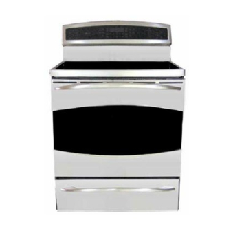
- Page 1 GE Consumer & Industrial Technical Service Guide May 2009 Profi le 30-in. Free Standing Induction Range PHB925SB1SS 31-9186 GE Appliances General Electric Company Louisville, Kentucky 40225...
- Page 2 If grounding wires, screws, straps, clips, nuts, or washers used to complete a path to ground are removed for service, they must be returned to their original position and properly fastened. GE Consumer & Industrial Technical Service Guide Copyright © 2009 All rights reserved.
-
Page 3: Table Of Contents
Table of Contents Aluminum Plate ................................49 Anti-Tip Bracket .................................20 Bake Element ..................................40 Bridge Board ..................................49 Broil Element ..................................37 Circuit Boards Connector Locator Views .......................26 Component Locator Views ............................21 Control Features ................................9 Control Panel ..................................47 Control Panel Assembly ..............................47 Control Panel Rear Cover .............................33 Convection Element .................................38 Convection Fan Assembly ............................39 Convection Fan Cover ..............................38... -
Page 4: Introduction
Introduction The Profi le 30-in. free standing induction range with convection oven and warming drawer features electronic oven and induction element controls. The induction elements provide unmatched cooking performance and fl exibility. Induction technology heats only the pan and its contents and offers energy effi... -
Page 5: Nomenclature
Nomenclature Model Number P H B 9 2 5 S B 1 S S Product Color SS = Stainless Steel Brand P = Profi le Indicator for Engineering Confi guration and Product Service Only H = Induction 30" Free Standing Model Year Designator Feature Pack Designates features–the higher... -
Page 6: Introduction To Induction Cooking
Introduction to Induction Cooking How Induction Cooking Works Induction cooking uses high frequency (20-50 K hz) Induction cooking is very effi cient. The energy magnetic energy to heat a ferrous metal pan when created by the induction coil is applied to only the it is placed over the induction coil. - Page 7 Using the correct size cookware Each cooking element requires a MINIMUM pan size. If the pan is properly centered, and 4 ¾" Min. Dia. 5 ¾" Min. Dia. 5-3/4” Min. Dia. 4-3/4” Min. Dia. of the correct material, but is too small for Pan Size Pan Size Pan Size...
-
Page 8: Suitable Cookware
Suitable Cookware Cookware “noise” Use quality cookware with heavier bottoms for better heat distribution Slight sounds may be produced by and even cooking results. Choose different types of cookware. Heavier cookware made of magnetic stainless pans such as enameled cast iron Use flat-bottomed pans. -
Page 9: Control Features
Control Features Using the oven controls. Throughout this manual, features and appearance may vary from your model. See the control panel below that matches your model. BROIL HI/LO Pad WARM Pad Touch to keep cooked foods warm. Touch the BROIL HI/LO pad once for HI Broil. To change to LO Broil, touch the BROIL HI/LO pad SLOW COOK Pad again. - Page 10 START Pad CONTROL LOCKOUT Pad Must be touched to start any cooking or cleaning Your control will allow you to lock out the touch function. pads and the cooktop so they cannot be activated when touched. OVEN LIGHT Pad Touch to turn the oven lights on or off. To lock the controls and cooktop: TIMER ON/OFF Pads Touch and hold the CONTROL LOCKOUT pad for 3...
-
Page 11: Special Features Of Your Oven Control
Special features of your oven control. Your new touch pad control has additional features that you may choose to use. The following are the features and how you may activate them. The special feature modes can only be activated while the display is showing the time of day. They remain in the control’s memory until the steps are repeated. - Page 12 Special features of your oven control. Tone Volume This feature allows you to adjust the tone Touch the COOK TIME pad again. The volumes to a more acceptable volume. There display will show 1 BEEP. This is the are three possible volume levels. quietest volume level.
-
Page 13: Using The Sabbath Feature
Using the Sabbath feature. (Designed for use on the Jewish Sabbath and Holidays) The Sabbath feature can be used for baking/roasting only. It cannot be used for convection, broiling, self-cleaning or Delay Start cooking. Note: The oven light comes on automatically when the door is opened and goes off when the door is closed. The bulb may be removed. -
Page 14: Using The Warming Drawer
How to Exit the Sabbath Feature Choose 12 shdn, indicating that the Touch the CLEAR/OFF pad. oven will automatically turn off after If the oven is cooking, wait for a random 12 hours or no shdn, indicating that delay period of approximately 30 the oven will not automatically turn off seconds to 1 minute, until only is in... -
Page 15: Features Of Your Cooktop
Features of your cooktop. Throughout this manual, features and appearance may vary from your model. Warmer 6" - 1800 Watts 7" - 2500 Watts 100 Watts 11" - 3700 Watts 7" - 2500 Watts ARMING IMMER IMMER ELECT IMMER IMMER Feature Index Cooking Elements Element Location Indicator (one for each element) - Page 16 Using the surface units—Touch pad-controlled models. Surface Unit Cook Settings he cooktop offers 19 power levels. Power levels range from “L” to H in precise halfstep increments. For example: 1, 1-1/2, 2, 2-1/2 and up to H. The power level with a fraction indicates Power Level “L”, the lowest setting, is the additional half-step setting.
- Page 17 Power Boil Power Boil is the highest power level, NOTE: If the pan is removed, the display will designed for large quantity rapid cooking fl ash “H”. After 30 seconds, the element will and boiling. Power Boil will operate for a turn off automatically.
-
Page 18: Setting The Controls
Setting the controls Using the "L" Low Setting The Low setting will keep hot, cooked food at Place a pan with food onto the serving temperature. Always start with hot induction element. The pan size should food. Do not use to heat cold food. match the indicator ring. -
Page 19: Operation Overview
Operation Overview The controls for the oven system consist of a Oven Flow Chart key panel touch-fi lm-on-glass assembly and main logic board with its model-select resistor Touch plug located in the control panel. There is also Control one RTD oven sensor, optional meat probe, and a motor door lock assembly with position switches. -
Page 20: Anti-Tip Bracket
Installation You must use a 3-wire, single-phase A.C. 08Y/120 BOOST MODE AND POWER SHARING Volt or 240/120 Volt, 60 hertz electrical system. If The induction coils on the left side are paired the electrical service provided does not meet the for power sharing and both cannot be used above specifi... -
Page 21: Component Locator Views
Component Locator Views Front View Control Panel (Continued next page) – 21 –... - Page 22 Oven and Warming Drawer - Front View Door Lock Meat Probe Outlet Door Switch Light Broil Element Oven Temperature Sensor Convection Fan and Element Hidden Bake Element Warming Drawer Element Shown with oven door and warming drawer removed (Continued next page) –...
-
Page 23: Control Panel
Control Panel Display Board Main Logic Board* Display Board Shown in service position Main Top Hot Surface Indicator Light Assembly Induction Module Thermal Switch Door Lock Motor (Continued next page) – 23 –... -
Page 24: Cooktop Elements
Cooktop Elements Induction Element Warming Element Induction Element Induction Element Induction Element Bridge Board Induction Module Cooling Fan Filter Board Right Generator Board Left Generator Board (Continued next page) – 24 –... - Page 25 Rear View Main Logic Board Left Wing Board Right Wing Board Broil Element Oven Temperature Sensor Convection Element Convection Fan Motor Relay Power Supply Module (RPSM) Convection Fan Motor Capacitor Warming Drawer Element Note: The oven bake element terminals are located behind the left side panel.
-
Page 26: Circuit Boards Connector Locator Views
Circuit Boards Connector Locator Views Relay Power Supply Module J7 - Door Lock Motor, Warming Zone, Jumper Wire K8 to K1, Warming Drawer Element, Neutral, Oven Light, Convection Fan Motor Direction J10 - Ground J11 - Neutral Standby J14 - L1 J16 - Oven Lock Switch, Oven Unlock Switch J17 - Communication Cable (Linbus) J20 - 240 VAC... - Page 27 Electronic Range Control Board J821 J841 J501 J241 J751 J201 J201 - Model Selector J241 - Linbus J501 - Oven Sensor, Meat Probe J751 - Oven Touch Panel Board J821 - Left Side Touch Panel Board J841 - Right Side Touch Panel Board –...
-
Page 28: Oven Door Assembly
Range Components Lift door up until the hinge arms are clear of the WARNING: Sharp edges may be exposed when slots. servicing. Use caution to avoid injury. Wear Kevlar gloves or equivalent protection. Oven Door Assembly The oven door can be separated into 2 assemblies. The outer assembly consists of the outer door frame, outer glass, heat defl... - Page 29 To remove the inner door assembly: To replace the inner door assembly: Remove the door. See previous page. Remove the inner door assembly. (See To remove the inner door assembly.) Place the door assembly, gasket side up, on a protective surface. Remove the three T-20 Torx screws (3 on each side) that attach each door hinge to the inner Remove the three 1/4-in.
- Page 30 Remove the six 1/4-in. hex-head screws that Air enters the door assembly through large slots in hold the heat barrier to the inner door. Remove the bottom and fl ows upward between the inner the heat barrier. and outer assemblies, exhausting through slots in the top of the door.
- Page 31 To replace the outer door assembly: 6. Slide the bottom trim and the glass out of the outer door frame. Remove the inner door assembly. (See remove the inner door assembly, this section.) Remove the two 1/4-in. hex-head screws from the heat defl...
-
Page 32: Cooktop Assembly
4. Disconnect the wire harness that connects the Warming Drawer Assembly warming zone to the range wiring. To remove and replace the warming drawer 5. Remove the 1/4-in. hex-head screw that assembly: attaches the cooktop ground wire to the back of the range. -
Page 33: Control Panel Rear Cover
Caution: To prevent damage to the cooktop, do not Rear Cover Removal raise the cooktop more than 45 degrees. To remove the rear cover: 8. Lift the front of the cooktop panel upward approximately 4 inches. Disconnect power to the range. 9. -
Page 34: Side Panel Removal
7. Remove the T-15 Torx screw and the 1/4-in hex- Side Panel Removal head screw from the top of the side panal. The procedures to remove both the left and right 8. Remove the Phillips-head screw and maintop side panels are identical. strike from the top of the side panel. -
Page 35: Door Switch
Door Switch Oven Door Hinge Receiver The oven utilizes a door switch located on the left To remove the hinge receiver: side of the door frame that is accessible from the Remove the side panel. (See Side Panel Removal front. The oven door switch monitors the position of the oven door and provides this information to the Note: If replacing the left side hinge receiver, it is oven's control board. -
Page 36: Oven Components
Oven Components Relay Power Supply Module (RPSM) Oven Temperature Sensor To remove the RPSM: The oven temperature sensor is connected to the electronic range control at location J501. The oven Remove the rear cover. (See Rear Cover Removal temperature sensor has an approximate resistance Note: In the following step, do not remove the orange relay jumper wires. -
Page 37: Broil Element
Note: When reinstalling the sensor, use a small fl at- 3. Carefully pull, then lower the broiler element blade screwdriver to push and guide the sensor wire towards the front of the oven. harness into the oven liner. 4. Disconnect the wires from the broiler element. Disconnect Disconnect Note: Upon reassembly, ensure displaced insulation... -
Page 38: Convection Element
To remove the convection bake element: Convection Fan Cover Remove the convection fan cover. (See The convection fan cover is attached to the back Convection Fan Cover wall of the oven with four 1/4-in. hex-head screws. It is necessary to remove the oven racks and it is 2. -
Page 39: Convection Fan Assembly
2. Remove the fan blade nut. Convection Fan Assembly The convection fan assembly is located on the back wall of the oven cavity and consists of the convection cover, fan blade, and motor. The fan motor utilizes a capacitor that can be accessed from the back of the range. -
Page 40: Bake Element
4. Carefully peel the refl ective tape from the Bake Element induction module air inlet vent. • The element is rated at 2850 watts, has an 5. Grasp the bottom of the air tunnel. Push it up approximate resistance value of 20 Ω, and approximately 3/4 inch, swing out the bottom draws approximately 12 amps. - Page 41 9. Disengage the hook of the left side wire 14. Using a small fl at blade screwdriver, pry the left insulation retainer from the frame of the range. side of the retainer away from the element. 10. Disconnect the 2 wires from the bake element. Disconnect Left Side Retainer Disconnect...
-
Page 42: Meat Probe And Outlet
Meat Probe and Outlet Smoke Eliminator/Vent Tube The oven is equipped with a meat probe outlet. The The oven is equipped with a smoke eliminator and meat probe outlet is connected to the electronic an oven vent tube. The smoke eliminator and vent range control at location J501. -
Page 43: Oven Light Assembly
6. Lift the cooktop upward and over the hinge Oven Light Assembly pins and place it on the range as shown. (See Cooktop Assembly The oven is equipped with a halogen light assembly located on the ceiling of the oven. The oven door switch monitors the position of the oven door and provides this information to the control board. -
Page 44: Door Lock Assembly
Door Locked Door Lock Assembly Hook Pulled In - Top Switch Closed - Bottom Switch Open The door lock assembly consists of a lock motor Lock Assembly Wire Harness cam and switch assembly, lock hook, and mounting plate. The lock motor is energized when the control is set for CLEAN and CLEAN TIME is selected. -
Page 45: High Limit Thermostat
To remove the oven door lock assembly: High Limit Thermostat Disconnect power to the range. In the event of an over-heat condition under the cooktop, the high limit thermostat will open at 350°F. Open the oven door. (See Oven Door Assembly. and disconnect L2 voltage from the bake, broil, Raise and support the cooktop. -
Page 46: Warming Drawer Element
Warming Drawer Temperature Characteristics Warming Drawer Element Warming drawer temperatures are controlled by • The warming drawer element is rated at 400 duty cycling algorithms. watts, has an approximate resistance value of 36 Ω, and draws approximately 3.3 amps. Low Temperature = 165° +/- 25°F. •... -
Page 47: Control Panel
Control Panel Assembly Main Logic Board Control Panel The control panel contains the main logic board and The main logic board is located inside the control the glass touch controls. panel. The main logic board is held to the control panel with two screws at the top and 2 tabs at the To remove the control panel: bottom. -
Page 48: Glass Touch Panel
Glass Touch Panel To remove the glass touch panel: Remove the main logic board. (See Main Logic Board.) Remove the 1/4-in. hex-head screw that attaches the control panel ground wire. 3. Place the control panel in the service position. (See Control Panel 4. -
Page 49: Aluminum Plate
Cooktop Components Aluminum Plate 5. Lift the aluminum plate from the cooktop. To remove the aluminum plate: Remove the cooktop assembly. (See Cooktop Assembly Place the cooktop topside down on a protective surface. Remove the seven 3/8-in. hex-head nuts and spacers. -
Page 50: Cooktop Elements
7. Lift and fold back the insulation from the wire Cooktop Elements entry in the aluminum plate. Induction Elements Each induction element consists of a coil and a sensor. The resistance value of the coil is less than 1 Ω at room temperature. The resistance value of the sensor is 1000 Ω... - Page 51 Note: On the 11-in. element, the choke must be To remove the warming zone element: removed and transferred to the replacement Remove the aluminum plate. (See Aluminum element. The choke must be attached at the same Plate location on the wires and secured with a plastic wire tie.
-
Page 52: Linbus Connectors
Do not use front-to-back motion to remove LINbus LINbus Connectors connector. Caution: To prevent damage to LINbus (Local Interconnect Network bus) connections, properly use (as shown below) a Molex 69008-1070 tool when INCORRECT removing LINbus connectors. Note: A Molex 69008-1070 tool will be provided with any part that requires the LINbus connectors to be removed. -
Page 53: Induction Module
6. Lift the front of the aluminum plate up and Induction Module disconnect the ground wire. To remove the induction module: Remove the cooktop elements. (See Cooktop Elements Mark and disconnect the 3 wire harnesses from the bridge board. Remove the plastic wire tie from the aluminum plate. -
Page 54: Generator Boards
3. Mark the location of the black L1 and the blue L2 Generator Boards wires and disconnect both from the generator board. To remove the generator boards: Note: When replacing the L1 and L2 wiring Remove the induction module. (See Induction connecting the fi... -
Page 55: Filter Board
8. Mark the location, then disconnect the black L1, Filter Board blue L2, and ground wire connections on the fi lter board. To remove the main fi lter board: 9. Disconnect the thermal cut-out and fi lter-to- Remove the induction module. (See Induction bridge wire harnesses. -
Page 56: Diagnostics And Service Information
Diagnostics and Service Information ERC Failure Codes The ERC (electronic range control) has error (F) codes that can be utilized by the service technician in order to quickly identify failed or improper operation of certain range components. F-codes are not shown on the display when they occur;... - Page 57 The display then shows F-cd and prompts for an UPPER or LOWER selection. Press 1 for the Oven. F-cd UPPER LOWER After selecting 1 for the oven, a log is shown. 6A - - UPPER Details of any one of up to 7 stored codes can be recalled by pressing a numbered key. F311 UPPER (Continued next page)
- Page 58 The F-Code log can be erased by pressing 9 and 0 together while the log is being displayed. Note: Only the log displayed is erased / cleared. - - - - - - - UPPER Press CLEAR/OFF to exit the F-Code mode and return to the time of day display. 11:24 Bad Line Display A bAd LinE will be displayed to signal a terminal block cord miswire.
-
Page 59: Oven Failure Codes
Oven Failure Codes X=1 For All Oven Failure Codes F-Code Meaning Correction F100 LED error on Burner Touch Board LEDs on Burner Touch Board operating properly. (when equipped) Harness /header pins to Burner Touch Board. F20x Temperature inside oven cavity a) Welded relay contacts exceeds 600°F with door unlocked b) High resistance in sensor connectors, especially... -
Page 60: Induction Failure Codes
F790 Main Logic Board internal touch key Replace Main Logic Board. chip signal error F7A0 Main Logic Board internal touch key Replace Main Logic Board. chip memory error F7B0 Main Logic Board internal touch key Replace Main Logic Board. chip memory error F800 Main Logic Board memory error Replace Main Logic Board. - Page 61 Test Mode To enter the test mode, disconnect power to the range for 5 seconds, reconnect power, then press keys 1 and 5. The display will show tESt. A test feature is selected by pressing certain individual keys. When selected, each test feature will remain displayed for 10 seconds, then the display will return to tESt. To exit the test mode, touch the Clear Off pad.
- Page 62 Convection Fan Troubleshooting Table Symptom Possibility Correction Fan motor buzzes Open capacitor Harness, terminals or bad capacitor. No fan operation Open winding as indicated Replace motor. by ohm check red to gray and blue to gray (approx. 60 ohms each) Fan loud Loose shaft nut Tighten shaft nut.
-
Page 63: Oven Sensor And Door Switch Test
Oven Sensor and Door Switch Test Note: See for door switch function explanation. Door Lock Assembly Remove power from oven. Make resistance measurement from side of sensor and lock switch connector with exposed terminals. The resistance measurements are made on the relay board and the main logic board with the control panel in the service position. -
Page 64: Schematics And Wiring Diagrams
Schematics and Wiring Diagrams WARNING: Disconnect electrical power before servicing. Caution: Label all wires prior to disconnection. Wiring errors can cause improper and dangerous operation. Verify operation after servicing. Schematic Note: All relays designated MK and K are located on the RPSM. * Used only in factory test. - Page 65 Wiring Diagram – 65 –...
-
Page 66: Warranty
This warranty is extended to the original purchaser and any succeeding owner for products purchased for home use within the USA. If the product is located in an area where service by a GE Authorized Servicer is not available, you may be responsible for a trip charge or you may be required to bring the product to an Authorized GE Service location for service.
Need help?
Do you have a question about the Profile PHB925SB1SS and is the answer not in the manual?
Questions and answers