
Related Manuals for Transition Networks Milan MIL-SM8002TG


Summary of Contents for Transition Networks Milan MIL-SM8002TG
-
Page 1: User Guide
MIL-SM8002TG 9 Port 10/100/1000BASE-T Two Combo 1000BASE-X SFP Ports Advanced Managed Switch User Guide Rev.A3 19-Mar-10... - Page 2 In no event shall Transition Networks be liable for incidental or consequential damages, costs, or expenses arising out of or in connection with the performance of the product delivered hereunder.
-
Page 3: Table Of Contents
Content Introduction......................1 Features ..........................1 Software Features ......................2 Package Contents ......................5 Hardware Description..................... 6 Physical Dimension ......................6 Front Panel ........................6 LED Indicators ........................7 Rear Panel.........................8 Desktop Installation ......................8 Power On...........................8 Network Application ....................9 Desktop Application ......................9 Indoor & Protected Outdoor Application ................9 X-Ring Application ......................9 X-Ring Application ......................10 Coupling Ring Application....................11... - Page 4 SNMP Commands Set.....................30 Port Mirroring Commands Set ..................33 802.1x Commands Set ....................33 TFTP Commands Set ......................36 SystemLog, SMTP and Event Commands Set ..............36 SNTP Commands Set .....................38 X-ring Commands Set .....................40 Main Menu ........................40 System Configuration ......................42 System Information....................42 IP Configuration......................44 DHCP Configuration ....................45 DHCP Server Configuration ................46 DHCP Client Entries..................47...
- Page 5 Rate Limiting........................65 Protocol Configuration .....................67 VLAN Configuration....................67 Port Base VLAN Configure................68 Group Add....................69 Group Remove ...................70 Group List....................71 802.1Q VLAN Configure..................72 GVRP Setting.....................73 Configure VLAN by Port ................74 VLAN List ....................75 Rapid Spanning Tree....................76 RSTP System Configuration................77 RSTP Per Port Configuration ................78 SNMP Configuration....................80 System Options ....................81 Community Strings ....................82...
- Page 6 IGMP Status ....................101 X-ring ..........................101 Security Configuration ....................103 Security Configuration ....................104 802.1X/ Radius Configuration.................104 System Configuration ..................105 802.1x Per Port Configuration .................106 Misc Configuration...................107 Port Security ......................108 Static MAC Address ..................109 Filtering MAC Address..................110 All MAC Address .....................111 Load Factory Default Setting ..................112 Save All Configuration ....................113 Reboot System ......................114 Web-Based Management ...................
- Page 7 User Authentication .......................129 Port Control ........................130 View the Single Port Information ................131 Port Trunk........................132 Aggregator setting ....................132 Note: the port trunk don’t support GVRP and X-ring..........134 Aggregator Information...................134 State Activity......................135 Port Mirroring .........................135 Rate Limiting........................136 VLAN configuration......................138 Port-based VLAN....................138 802.1Q VLAN ......................140 802.1Q Configuration ..................141 Group Configuration ..................143 Rapid Spanning Tree.....................145...
- Page 8 TOS Configuration....................156 SNTP Configuration.......................156 IGMP Configuration .......................159 X-ring ..........................161 Security-802.1x/Radius Configuration ................163 802.1X Configuration....................163 System Configuration ..................164 802.1x Port Configuration................165 Misc Configuration...................166 MAC Address Table ....................167 Static MAC Address ..................167 Filtering MAC Address..................168 All MAC Address .....................169 Factory Default ......................170 Save Configuration ......................171 System Reboot ......................171 Troubleshooting ....................
-
Page 9: Introduction
Introduction The product is a multi-port switch that can be used to build high-performance switched indoor or protected outdoor networks. It provides wire-speed, Gigabit Ethernet switching function that allows high-performance, low-cost connection. The Switch features a store-and-forward switching and it can automatically learn and store source address in an 8K-entry MAC address table. -
Page 10: Software Features
Broadcast storm filter DHCP Client, Relay, Server Per port band width control SNTP and SMTP support Management IP address security MAC address security System log SNMP Trap support Configuration up-load and down-load TFTP firmware update Web/SNMP/Telnet/CLI /RMON management Software Features SNMP v1, SNMP v2c, SNMP v3, Telnet, Management Console (Command line interface), Web... - Page 11 Support IEEE802.3ad with LACP function. Up Port Trunk to 3 trunk groups and maximum group member up to 8 ports. IEEE802.1d Spanning tree Spanning Tree IEEE802.1w Rapid spanning tree Port based VLAN Double Tag VLAN for management IEEE802.1Q Tag VLAN. VLAN The static VLAN groups up to 256 and dynamic VLAN groups up to 2048, the VLAN...
- Page 12 Global system supports 3 mirroring types: Port Mirror “RX, TX and Both packet”. The maximum of port mirror entries is up to 8. Ingress rate limiting packet type: all of frames, broadcast, multicast, unknown unicast and broadcast packet. Bandwidth Control Egress rate shaping supports all of packet.
-
Page 13: Package Contents
Support RFC2030 Simple Network Time Protocol and up to 5 NTP server. SMTP Up to 6 mail accounts. Configuration Support binary format configuration file for upload and system quick configuration. download Package Contents Unpack the contents of the switch and verify them against the checklist below. Managed Switch unit Power Cord Four Rubber Feet... -
Page 14: Hardware Description
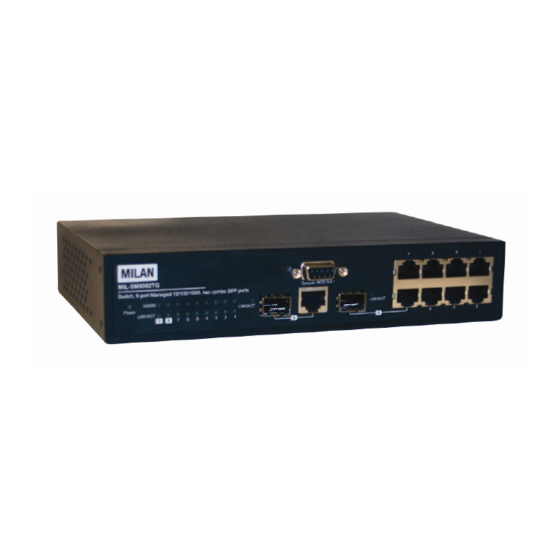
Hardware Description Physical Dimension The physical dimensions of the switch is 217mm(W) x 140mm(D) x 43mm(H) Front Panel The Front Panel of the switch consist of 9x auto-sensing 10/100/1000Mbps Ethernet RJ-45 ports (automatic MDI/MDIX), 2 SFP copper combo ports, and the LED indicators are also located on the frond panel of the switch. -
Page 15: Led Indicators
LED Indicators The following table provides descriptions of the LED statuses and meaning. They provide a real-time indication of systematic operation status. Status Description Power Green Power On The port is operating at the speed of Yellow 1000Mbps. The port is operating at the speed of 1000M Orange 100Mbps. -
Page 16: Rear Panel
Rear Panel The 3-pronged power plug are located at the Rear Panel of the switch as shown in figure. The Switches will work with AC in the range 90-240V AC, 50-60Hz. Rear Panel of the switch Desktop Installation Set the switch on a sufficiently large flat space with a power outlet nearby. The surface where you put your Switch should be clean, smooth, level, and sturdy. -
Page 17: Network Application
IP based technologies start dominating outdoor applications, that have been historically reserved for serial connectivity. Gigabit switches gradually leave traditional LANs and become a backbone for infrastructure connectivity and management. MIL-SM8002TG switches can interconnect IP-based Traffic control lights, Traffic Cameras and message... -
Page 18: X-Ring Application
X-Ring Application The switch supports the X-Ring protocol that can help the network system to recovery from network connection failure within 20ms or less, and make the network system more reliable. The X-Ring algorithm is similar to spanning tree protocol (STP) algorithm but its recovery time is faster than STP. -
Page 19: Coupling Ring Application
port to the failure. In the X-Ring group, switches are setting as “slave mode” by default, but one must be the “master mode”. If there are 2 or more switches in master mode, then software will automatically select the switch with lowest MAC address number as the ring master. -
Page 20: Dual Homing Application
Dual Homing Application It provides the connection loss from between X-Ring group and upper level/core switch. Assign two ports to be the Dual Homing port that is backup port in the X-Ring group. The Dual Homing function only works when the X-Ring function is active. Each X-Ring group only has one Dual Homing port. -
Page 21: Console Management
Console Management Connecting to the Console Port Use the supplied RS-232 cable to connect a terminal or PC to the console port. The terminal or PC to be connected must support the terminal emulation program. Connecting the switch to a terminal via RS-232 cable Login in the Console Interface When the connection between Switch and PC is ready, turn on the PC and run a terminal emulation program or Hyper Terminal and configure its communication parameters to... - Page 22 The settings of communication parameters After finished the parameter settings, click “OK“. When the blank screen shows up, press Enter key to bring out the login prompt. Key in the “root“(default value) for the both User name and Password (use Enter key to switch), then press Enter key and the Main Menu of console management appears.
- Page 23 Console login interface...
-
Page 24: Cli Management
CLI Management The system supports two types of console management – CLI command and Menu selection. After you login to the system, you will see a command prompt. To enter CLI management interface, enter “enable” command. The following table lists the CLI commands and description. - Page 25 ip dhcp Enable DHCP client switch(config)#ip dhcp function of switch show ip Switch#show ip Show IP information of switch no ip dhcp Disable DHCP client switch(config)#no ip dhcp function of switch Halt and perform a cold reload Switch(config)#reload restart default Restore to default Switch(config)#default admin username...
- Page 26 dhcpserver ipbinding Set static IP for DHCP switch(config)#interface [IP address] clients by port fastEthernet 2 switch(config-if)#dhcpserver ipbinding 192.168.1.1 show dhcpserver Show configuration of switch#show dhcpserver configuration configuration DHCP server show dhcpserver clients Show client entries of switch#show dhcpserver clients DHCP server show dhcpserver Show IP-Binding switch#show dhcpserver...
-
Page 27: Port Commands Set
Port Commands Set Netstar Commands Level Description Example interface fastEthernet Choose the port for switch(config)#interface [Portid] modification. fastEthernet 2 duplex Use the duplex switch(config)#interface [full | half] configuration fastEthernet 2 switch(config-if)#duplex full command to specify the duplex mode of operation for Fast Ethernet. - Page 28 limit frame type to fastEthernet 2 “accept all frame” switch(config-if)#bandwidth type bandwidth type Set interface ingress switch(config)#interface broadcast-multicast-floo limit frame type to fastEthernet 2 ded-unicast switch(config-if)#bandwidth type “accept broadcast, multicast, and flooded broadcast-multicast-flooded-uni unicast frame” cast bandwidth type switch(config)#interface Set interface ingress broadcast-multicast limit frame type to fastEthernet 2...
-
Page 29: Trunk Commands Set
limit. show bandwidth Show interfaces switch(config)#interface bandwidth control fastEthernet 2 switch(config-if)#show bandwidth state Use the state interface switch(config)#interface [Enable | Disable] configuration fastEthernet 2 switch(config-if)#state Disable command to specify the state mode of operation for Ethernet ports. Use the disable form of this command to disable the port. - Page 30 [1~65535] priority aggregator activityport Set activity port switch(config)#aggregator [Group ID] activityport 2 2 [Port Numbers] aggregator group Assign a trunk group switch(config)#aggregator group [GroupID] [Port-list] 1 1-4 lacp workp 2 with LACP active. lacp [GroupID] :1~3 workp [Port-list]:Member port switch(config)#aggregator group [Workport] 2 1,4,3 lacp workp 3 list, This parameter...
-
Page 31: Vlan Commands Set
switch#show aggregator 3 no aggregator lacp Disable the LACP switch(config)#no aggreator lacp [GroupID] function of trunk group no aggregator group Remove a trunk group switch(config)#no aggreator [GroupID] group 2 VLAN Commands Set Netstar Commands Level Description Example vlan database switch#vlan database Enter VLAN configure mode Vlanmode... - Page 32 vlan 8021q name Change the name of switch(vlan)#vlan 8021q name [GroupName] VLAN group, if the test vid 22 group didn’t exist, this [VID] command can’t be applied. vlan 8021q port switch(vlan)#vlan 8021q port 3 Assign a access link [PortNumber] for VLAN by port, if the access-link untag 33 access-link untag port belong to a trunk...
-
Page 33: Spanning Tree Commands Set
vlan 8021q trunk Assign a trunk link for switch(vlan)#vlan 8021q trunk 3 [PortNumber] VLAN by trunk group trunk-link tag 2,3,6,99 trunk-link tag [TaggedVID List] switch(vlan)#vlan 8021q trunk 3 trunk-link tag 3-20 vlan 8021q trunk switch(vlan)#vlan 8021q trunk 3 Assign a hybrid link for [PortNumber] VLAN by trunk group hybrid-link untag 4 tag 3,6,8... - Page 34 the root switch within this interval, it recomputed the Spanning Tree Protocol (STP) topology. spanning-tree Use the spanning-tree switch(config)#spanning-tree hello-time [seconds] hello-time global hello-time 3 configuration command to specify the interval between hello bridge protocol data units (BPDUs). spanning-tree Use the spanning-tree switch(config)#spanning-tree forward-time [seconds]...
- Page 35 path cost for Spanning Tree Protocol (STP) calculations. In the event of a loop, spanning tree considers the path cost when selecting an interface to place into the forwarding state. stp-path-priority Use the spanning-tree switch(config)#interface [Port Priority] fastEthernet 2 port-priority interface configuration switch(config-if)#stp-path-priority command to configure...
-
Page 36: Qos Commands Set
tp False show spanning-tree Displays a summary of switch>show spanning-tree the spanning-tree states. no spanning-tree Disable spanning-tree. switch(config)#no spanning-tree QOS Commands Set Netstar Commands Level Description Example qos policy Select QOS policy switch(config)#qos policy [weighted-fair|strict] scheduling weighted-fair qos prioritytype Setting of QOS priority switch(config)#qos prioritytype [port-based|cos-only|tos type... -
Page 37: Mac / Filter Table Commands Set
switch(config)#i i i i gmp query auto igmp query auto Set IGMP query to auto mode switch(config)#i i i i gmp query force igmp query force Set IGMP query to force mode show igmp Displays the details of switch#show igmp configuration configuration an IGMP configuration. -
Page 38: Snmp Commands Set
static hwaddr MAC address table of fastEthernet 2 [MAC] interface (static) switch(config-if)#no mac-address-table static hwaddr 000012345678 no mac-address-table Remove an entry of switch(config)#no filter hwaddr mac-address-table filter hwaddr MAC address table [MAC] (filter) 000012348678 no mac-address-table Remove dynamic entry switch(config)#no mac-address-table of MAC address table SNMP Commands Set... - Page 39 [v1|v2c] no snmp-server host 192.168.1.50 snmpv3 context-name switch(config)#snmpv3 Configure the context [Context Name ] name context-name Test snmpv3 user Configure the switch(config)#snmpv3 user [User Name] test01 group G1 password userprofile for group SNMPV3 agent. AuthPW PrivPW [Group Name] Privacy password password could be empty.
- Page 40 [OID] show snmp Show SNMP switch#show snmp configuration no snmp Remove the specified switch(config)#no snmp community-strings community. community-strings public [Community] no snmp-server host Remove the SNMP switch(config)#no snmp-server [Host-address] server host. 192.168.1.50 no snmpv3 user Remove specified user switch(config)#no snmpv3 user [User Name] Test of SNMPv3 agent.
-
Page 41: Port Mirroring Commands Set
Port Mirroring Commands Set Netstar Commands Level Description Example monitor rx Set RX destination switch(config)#monitor rx [Port ID] port of monitor function monitor tx switch(config)#monitor tx Set TX destination port [Port ID] of monitor function show monitor Show port monitor switch#show monitor information monitor... - Page 42 8021x system serverport Use the 802.1x system switch(config)# 8021x system [port ID] server port global serverport 1815 configuration command to change the radius server port 8021x system switch(config)# 8021x system Use the 802.1x system accountport account port global accountport 1816 [port ID] configuration command to change...
- Page 43 8021x misc Use the 802.1x misc switch(config)# 8021x misc supportimeout [sec.] supp timeout global supportimeout 20 configuration command to set the supplicant timeout. 8021x misc switch(config)#8021x misc Use the 802.1x misc servertimeout [sec.] server timeout global servertimeout 20 configuration command to set the server timeout.
-
Page 44: Tftp Commands Set
function TFTP Commands Set Netstar Commands Level Description Defaults Example backup switch(config)#backup Save configuration to flash:backup_cfg flash:backup_cfg TFTP and need to specify the IP of TFTP server and the file name of image. restore flash:restore_cfg Get configuration from switch(config)#restore TFTP server and need to flash:restore_cfg specify the IP of TFTP server and the file name... - Page 45 functon smtp enable Enable SMTP function switch(config)#smtp enable smtp serverip switch(config)#smtp serverip Configure SMTP [IP address] server IP 192.168.1.5 smtp sender Configure sender of switch(config)#smtp sender [sendername] mail dut1@xxx.com smtp authentication switch(config)#smtp Enable SMTP authentication authentication smtp account Configure switch(config)#smtp account [account] John authentication account...
-
Page 46: Sntp Commands Set
[Link-UP|Link-Down|Bot SMTP fastethernet 3 switch(config-if)#event smtp both show event Show event selection switch#show event no event Disable cold start switch(config)#no event device-cold-start event type device-cold-start no event Disable Authentication switch(config)#no event authentication-failure failure event typ authentication-failure no event Disable X-ring switch(config)#no event X-ring-topology-change topology changed... - Page 47 this command can’t be applied. Parameter format: [yyyymmdd-hh:mm] sntp daylight-offset Set offset of daylight switch(config)#sntp [Minute] daylight-offset 3 saving time, if SNTP function is inactive, this command can’t be applied. sntp ip Set SNTP server IP, if switch(config)#sntp ip 192.169.1.1 [IP] SNTP function is inactive, this command...
-
Page 48: X-Ring Commands Set
X-ring Commands Set Netstar Commands Level Description Example ring enable Enable X-ring switch(config)#ring enable ring master switch(config)# ring master Enable ring master ring couplering Enable couple ring switch(config)#ring couplering ring dualhoming Enable dual homing switch(config)#ring dualhoming ring ringport Configure 1st/2nd switch(config)#ring ringport 7 8 [1st Ring Port] [2nd Ring Ring Port... - Page 49 limiting and mirroring. Protocol Configuration: Configure VLAN, RST, SNMP, QoS, SNTP, IGMP, and X-ring function. Security Configuration: Configure 802.1X, IP, and Port security function. Load Factory Default: Reset switch to default configuration. Save All Configuration: Save the configuration that user had made in the switch system.
-
Page 50: System Configuration
Enter: Select item. Space: Toggle selected item to next configure or change the value. Esc: to exit the current action mode. System Configuration In System Configuration, you can configure system event log, SMTP, system description, IP, DHCP, login security and firmware update. You can press the “Tab” or “Backspace” to choose the item, and press “Enter”... - Page 51 You can configure the name, description, location, contact of the system. Also, you can view the version of firmware, hardware, kernel and MAC address. Name: the name of device. Description: the name of device type. Location: where the device is located. Contact: the contact person or information.
-
Page 52: Ip Configuration
IP Configuration You can configure the IP for the switch. The system has the default IP address. You can re-configure or use the default value. 1. DHCP: disable or enable the DHCP client function. When DHCP function is enabling, you don’t need to assign the IP address and subnet mask. The system will be assigned the IP address from the local DHCP server. -
Page 53: Dhcp Configuration
IP Configuration interface DHCP Configuration It short for Dynamic Host Configuration Protocol that is a protocol for assigning dynamic IP addresses to devices on a network. With dynamic addressing, a device can have a different IP address every time it connects to the network. In some systems, the device's IP address can even change while it is still connected. -
Page 54: Dhcp Server Configuration
DHCP Configuration interface DHCP Server Configuration The system provides the DHCP server function. Enable the DHCP server function, the switch system will be a DHCP server. DHCP Server: Enable or Disable the DHCP Server function. Enable – the switch will be the DHCP server on your local network. -
Page 55: Dhcp Client Entries
Gateway: the gateway in your network. DNS: Domain Name Server IP Address in your network. Lease Time (sec): It is the time period that system will reset the dynamic IP assignment to ensure the dynamic IP will not been occupied for a long time or the server doesn’t know that the dynamic IP is idle. -
Page 56: Port And Ip Bindings
DHCP Client Entries interface Port and IP Bindings You can assign the specific IP address that is the IP in dynamic IP assign range to the specific port. When the device is connecting to the port and asks for dynamic IP assigning, the system will assign the IP address that has been assigned before to the connected device. -
Page 57: Firmware Update
Port and IP Bindings interface Firmware Update It provides user to update firmware or restore EEPROM value or backup current EEPROM value. 1. Start the TFTP server, and copy new firmware version image file to the TFTP server. 2. TFTP Server IP: type the IP of TFTP server. 3. -
Page 58: System Event Log
4. File Name: type the image file name. 5. Press “ESC” to back to action line. 6. “Save” the configuration. Firmware Update interface System Event Log You can configure the switch as the system log client that can view the system log information that from the system log server that you have assigned. -
Page 59: System Log Configuration
System Log Configuration interface System Log Configuration Configuring the system event mode that want to be collected and system log server 1. Collection Mode: select the system log mode – client only, server only, or both S/C. 2. System Log Server IP Address: assigned the system log server IP. -
Page 60: Event Configuration
System Log Configuration interface Event Configuration You can select the system log and SMTP events. When selected events occur, the system will send out the log information or alert. Device cold start: when the device executes cold start action, the system will produce a log event. -
Page 61: Email Alert Configuration
Email Alert Configuration When the specific events occur, the system will send the alert to the email account that is assigned by user. -
Page 62: Smtp Configuration
Email Alert Configuration interface SMTP Configuration You can set up the mail server IP, mail account, and account password. Email Alert: enable or disable the email alert function. SMTP Server IP: set up the mail server IP address. Authentication: mark the check box to enable and configure the email account and password for authentication. -
Page 63: Recipient's Email Configuration
SMTP Configuration interface Recipient’s email Configuration Assign the forwarded email account for receiving the event alert. Rcpt E-mail Address 1 ~ 6: you can assign up to 6 e-mail accounts also to receive the alert. -
Page 64: Security Manager
Recipient’s email Configuration interface Security Manager You can change the console and web management login user name and password for the security issue. User Name: Enter the new user name. The default user name is “root”. New Password: enter the new password. The default password is “root” Confirm Password: reenter the new password for confirmation. - Page 65 Security Manager interface...
-
Page 66: Port Configuration
Port Configuration In this section, you can view port counter information; configure port control, mirroring, trunk, and rate limiting. Port Configuration main interface Port Counters It displays the current port counter information. Select the <Refresh>action to get newest port counter information. Select the <Clear> action to set the port counter information back to 0. -
Page 67: Port Control Configuration
Port Counter interface Port Control Configuration You can set up every port status. Use “Tab” key to move between items. Port: select the port that wants to be configured. State: Current port status. The port can be set to disable or enable mode. If the port setting is disable then will not receive or transmit any packet. -
Page 68: Trunk Configuration
To view the State of Ports, select <Refresh> to get the current ports state information. Port Control Configuration interface Trunk Configuration The Link Aggregation Control Protocol (LACP) provides a standardized means for exchanging information between Partner Systems on a link to allow their Link Aggregation Control instances to reach agreement on the identity of the Link Aggregation Group to which the link belongs, move the link to that Link Aggregation Group, and enable its transmission and reception functions in an orderly manner. -
Page 69: Aggregator Setting
mode, more detail information refers to IEEE 802.3ad. Aggregator setting System Priority: a value used to identify the active LACP. The switch with the lowest value has the highest priority and is selected as the active LACP. LACP Configuration: If enable, the group is LACP static trunk group. If disable, the group is local static trunk group. -
Page 70: Aggregator Information
Trunk Configuration — Aggregator Setting interface Aggregator Information When you had setup the LACP aggregator, you will see relate information in here. -
Page 71: State Activity
Trunk Configuration – Aggregator Information interface State Activity When you had setup the LACP aggregator, you can configure port state activity. You can change the port state activity to Active or Passive. Active: The port automatically sends LACP protocol packets. Passive: The port does not automatically send LACP protocol packets, and responds only if it receives LACP protocol packets from the opposite device. -
Page 72: Port Mirroring Configuration
If you are active LACP’s actor, when you are select trunking port, the active status will be created automatically. Trunk Configuration ─ State Activity Port Mirroring Configuration The port mirroring is a method for monitor traffic of switched networks. The specific port can monitor traffic through the mirror ports. -
Page 73: Rate Limiting
port wants to monitor in only one mirror mode. RX: RX packet only TX: TX packet only Both: RX and TX packet Port Mirroring interface Rate Limiting You can set up every port’s bandwidth rate and packet limitation type. Ingress Limit Packet type: select the packet type that want to filter. The packet types have type... - Page 74 broadcast packet only are only for ingress packet. The egress rate only supports all type packet. All the ports support port ingress and egress rate control. For example, assume port 1 is 10Mbps, users can set it’s effective egress rate is 1Mbps, ingress rate is 500Kbps. The switch performs the ingress rate by packet counter to meet the specified rate.
-
Page 75: Protocol Configuration
Protocol Configuration In this section, you can configure VLAN, RST, SNMP, SNTP, QoS, IGMP, and X-ring. Protocol Configuration interface VLAN Configuration The VLAN Configuration provides two VLAN modes – Port Base and 802.1Q. You need to select the VLAN mode for the VLAN detail configuration. Use Space key to switch the VLAN mode selection. -
Page 76: Port Base Vlan Configure
VLAN Mode Selection interface Port Base VLAN Configure Add VLAN group, remove VLAN group, and view the VLAN group list. Use Tab key to move between the configure items. -
Page 77: Group Add
Group Add Group Name: Type a name for the new VLAN, ex: VLAN01. VID: Type the VLAN group ID. The group ID rang is from 1 to 4094. a. Member Ports: Press”Space” key to change the port status. Mark the port to be the member.. -
Page 78: Group Remove
Group Add interface Group Remove You can remove unwanted VLAN group. Enter the group VID and select Save. -
Page 79: Group List
Group Remove interface Group List Display the all VLAN groups’ information. -
Page 80: Q Vlan Configure
Group List interface 802.1Q VLAN Configure You configure GVRP setting, VLAN by port, and edit VLAN group. -
Page 81: Gvrp Setting
802.1Q VLAN Configuration interface GVRP Setting GVRP (Generic Attribute Registration Protocol) is an application defined in the IEEE 802.1Q standard that allows for the control of VLANs. Use Space key to change the GVRP setting – Disable or Enable. And then, select the Save to apply the setting. -
Page 82: Configure Vlan By Port
GVRP Setting interface Configure VLAN by Port Select the port that wants to configure by using Spec key. Submit to get the port current setting. Link Type: there are 3 link types. Untagged VID: assign the untagged frame VID. Tagged VID: assign the tagged frame VID. Save the configuration. -
Page 83: Vlan List
Configure VLAN by Port interface VLAN List Enable or disable the VLAN group. 1. Group Name: you can rename the group name. 2. On/Del: On is active the VLAN group. Del is removing the VLAN group. 3. After editing, Apply the change. -
Page 84: Rapid Spanning Tree
Edit VLAN Group interface Rapid Spanning Tree The Rapid Spanning Tree Protocol (RSTP) is an evolution of the Spanning Tree Protocol and provides for faster spanning tree convergence after a topology change. The system also supports STP and the system will auto detect the connected device that is running STP or RSTP protocol. -
Page 85: Rstp System Configuration
Rapid Spanning Tree interface RSTP System Configuration You can view spanning tree information about the Root Bridge. You can modify RSTP state. After modification, save the configuration. RSTP mode: you must enable or disable RSTP function before configure the related parameters. Priority (0-61440): a value used to identify the root bridge. -
Page 86: Rstp Per Port Configuration
Hello Time (1-10): the time that controls switch sends out the BPDU packet to check RSTP current status. Enter a value between 1 through 10. Forward Delay Time (4-30): the number of seconds a port waits before changing from its Rapid Spanning-Tree Protocol learning and listening states to the forwarding state. - Page 87 You can configure path cost and priority of every port. 1. Select the port in Port column. 2. Path Cost: The cost of the path to the other bridge from this transmitting bridge at the specified port. Enter a number 1 through 200000000. 3.
-
Page 88: Snmp Configuration
RSTP Per Port Configuration interface SNMP Configuration Simple Network Management Protocol (SNMP) is the protocol developed to manage nodes (servers, workstations, routers, switches and hubs etc.) on an IP network. SNMP enables network administrators to manage network performance, find and solve network problems, and plan for network growth. -
Page 89: System Options
SNMP Configuration interface System Options Enter the system name, contact, and location information. Name: assign a name for the switch. Contact: Type the name of contact person or organization. Location: Type the location of the switch. Agent Mode: Select the SNMP version that you want to use it. <Save>... -
Page 90: Community Strings
SNMP System Options interface Community Strings You can change the default community string that public and private attribute and define two more set community string. Community Name: It uses for authenticating the manager to allow access the agent. Type the name of community strings. The Public and Private Community string cannot be changed the name. -
Page 91: Trap Managers
Save the configuration. Add Community Strings interface Trap Managers A trap manager is a management station that receives traps, the system alerts generated by the switch. If no trap manager is defined, no traps will issue. Create a trap manager by entering the IP address of the station and a community string. -
Page 92: Snmp V 3 Configuration
To disable the trap manager, please delete the trap manager IP, community string and version. And then, save to change. Trap Managers interface SNMP V 3 Configuration Configure the SNMP V3 function. -
Page 93: Context Table
SNMP V3 configuration interface Context Table Configure SNMP v3 context table. Assign the context name of context table. -
Page 94: User Table
SNMP v3_Context Table interface User Table Configure SNMP v3 user table.. User Name: set up the user name. Auth Password: set up the authentication password. Priv Password: set up the private password. <Save> to save all configure... -
Page 95: Group Table
SNMP v3_User Table interface Group Table Configure SNMP v3 group table. User Name: assign the user name that you have set up in user table. Group Name: set up the group name. <Save> to save all configure... -
Page 96: Access Table
SNMP v3_Group Table interface Access Table Configure SNMP v3 access table. - Page 97 SNMP v3_AccessTable interface Add Table Add the access table. Context: set up the context name. Group: set up the group. Sec Level: select the access level. Read View: set up the read view. Write View: set up the write view. <Save>...
- Page 98 Remove/Browse Table Remove and Browse access table.
-
Page 99: Mibview Table
MIBview Table Configure MIB view table. - Page 100 SNMP v3_MIBviewTable interface Add Table Add MIB view table. ViewName: set up the name. Type: select the type – exclude or include. Sub-Oid: fill the Sub OID. <Save> to save all configure...
- Page 101 Remove/Browse Table Remove and Browse MIBview table.
-
Page 102: Qos Configuration
QoS Configuration You can configure Qos policy and priority setting, per port priority setting, COS and TOS setting. -
Page 103: Qos Policy And Priority Type
QoS Configuration interface QoS Policy and Priority Type Select the Oos Policy: select the Qos policy rule. Using the 8,4,2,1 wnine fair queue scheme: the switch will follow 8:4:2:1 rate to process priority queue from Hi to lowest queue. For example: the system will process 8 high queue packets, 4 middle queue packets, 2 low queue packets, and the one lowest queue packets at the same time. -
Page 104: Default Port Priority
assigned. TOS only: the port priority will only follow the TOS priority that you have assigned. COS first: the port priority will follow the COS priority first, and then other priority rule. TOS first: the port priority will follow the TOS priority first, and the other priority rule. -
Page 105: Cos Configuration
Save the configuration. Default Port Priority Setting interface COS Configuration Set up the COS priority level. COS priority:. Set up the COS priority level 0~7 –High, Middle, Low, Lowest. Save the configuration. -
Page 106: Tos Configuration
COS Configuration interface TOS Configuration Set up the TOS priority. TOS priority: the system provides 0~63 TOS priority level. Each level has 4 types of priority – high, mid, low, and lowest. The default value is “Lowest” priority for each level. When the IP packet is received, the system will check the TOS level value in the IP packet that has received. -
Page 107: Igmp Configuration
TOS Configuration interface IGMP Configuration The Internet Group Management Protocol (IGMP) is an internal protocol of the Internet Protocol (IP) suite. IP manages multicast traffic by using switches, routers, and hosts that support IGMP. Enabling IGMP allows the ports to detect IGMP queries and report packets and manage IP multicast traffic through the switch. -
Page 108: Igmp Configuration
A message sent by a host to the querier to indicate that the host wants to be or is a member of a given group indicated in the Report report message. A message sent by a host to the querier to indicate that the host Leave has quit being a member of a specific multicast group. -
Page 109: Igmp Status
IGMP Configuration interface IGMP Status When you enable the IGMP query you will see the relate information show as following figure. IGMP Status interface X-ring X-ring provide a faster redundant recovery than Spanning Tree topology. The action is similar with STP or RSTP, but the algorithms not the same. - Page 110 In the X-ring topology, every switch should enable X-ring function and assign two member ports in the ring. Only one switch in the X-ring group would be set as a backup switch that one of two member ports would be blocking, called backup port, and another port is called working port.
- Page 111 X-ring Interface [NOTE] When you enable the X-ring function, you must disable the RSTP. The X-ring function and RSTP function cannot exist at the same time.
-
Page 112: Security Configuration
Security Configuration In this section, you can configure 802.1x, IP, and port security. Security Configuration interface 802.1X/ Radius Configuration 802.1x is an IEEE authentication specification that allows a client to connect to a wireless access point or wired switch but prevents the client from gaining access to the Internet until it provides authority, like a user name and password that are verified by a separate server. -
Page 113: System Configuration
802.1x Configuration interface System Configuration After enabling the IEEE 802.1X function, you can configure the parameters of this function. IEEE 802.1x mode: .enable or disable 802.1x protocol. Radius Server IP: set the Radius Server IP address. Server Port: set the UDP destination port for authentication requests to the specified Radius Server. -
Page 114: X Per Port Configuration
NAS, Identifier: set the identifier for the radius client. Save the configuration. 802.1x System Configuration interface 802.1x Per Port Configuration You can configure 802.1x authentication state for each port. The State provides Disable, Accept, Reject and Authorize. Use “Space” key change the state value. Reject: the specified port is required to be held in the unauthorized state. -
Page 115: Misc Configuration
802.1x Per Port Setting interface Misc Configuration Quiet Period: set the period during which the port doesn’t try to acquire a supplicant. TX Period: set the period the port wait for retransmit next EAPOL PDU during an authentication session. Supplicant Timeout: set the period of time the switch wait for a supplicant response to an EAP request. -
Page 116: Port Security
re-authenticated. Select <Save> 802.1x Misc Configuration interface Port Security Use the MAC address to ensure the port security. -
Page 117: Static Mac Address
MAC Address Configuration interface Static MAC Address You can add a static MAC address; it remains in the switch's address table, regardless of whether the device is physically connected to the switch. This saves the switch from having to re-learn a device's MAC address when the disconnected or powered-off device is active on the network again. -
Page 118: Filtering Mac Address
Select <Add> to save all configure value. Existed Entry: you will see the added MAC address information in Exited Entry table. You can delete or keep the added MAC address. Static MAC Address interface Filtering MAC Address By filtering MAC address, the switch can easily filter pre-configure MAC address and reduce the un-safety. -
Page 119: All Mac Address
Add the Filtering MAC Address MAC Address: Enter the MAC address that you want to filter. VID: enter the Mac address’s VLAD ID, if the Mac address belongs to any VLAN group. Select <Add> to save all configure value. Existed Entry: you will see the added MAC address information in Exited Entry table. You can delete or keep the added MAC address Filtering MAC Address interface All MAC Address... -
Page 120: Load Factory Default Setting
All MAC Address interface The selected port of static MAC address information will display. Select the [Clear MAC Table] to clear the current port static MAC address information on screen. Load Factory Default Setting Reset switch to default configuration. Keep current IP address setting?: you can decided to keep the current IP address or reset to default IP address. -
Page 121: Save All Configuration
Load Factory Default Setting interface Save All Configuration Save all configurations that you have made in the system. To ensure the all configuration will be saved. Use the Space key to select the options – Yes or No. Yes means save all the configurations. -
Page 122: Reboot System
Save All Configuration interface Reboot System Reboot the switch in software reset. Use the Space key to select the options – Yes or No. Yes means reboot the system. No means don’t reboot the system. Use Tab key move to [Execute] action and press Enter key to reboot the system. - Page 123 Reboot System interface...
-
Page 124: Web-Based Management
Web-Based Management Web-Based management offers advanced management features and allow users to manage the switch from anywhere on the network through a standard browser such as Microsoft Internet Explorer. The Web-Based Management supports Internet Explorer 5.0. It is based on Java Applets with an aim to reduce network bandwidth consumption, enhance access speed and present an easy viewing screen. -
Page 125: System Information
Type http:// and the IP address of the switch. Press “Enter”. The login screen appears. Key in the user name and password. The default user name and password is “root”. Click “Enter” or” OK”, then the home screen of the Web-based management appears. -
Page 126: Ip Address
Firmware Version: display the switch’s firmware version. Kernel Version: display the kernel software version. Hardware version: display the switch hardware version. MAC Address: display the unique hardware address assigned by manufacturer (default). System Information interface IP Address User can configure the IP Settings and DHCP client function, than clicks Apply button. -
Page 127: Dhcp Configuration
domain name address. For example, the www.net.com might translate to 192.168.1.1. DNS2: The backup for DNS1. When the DNS1 cannot function, the DNS2 can replace DNS1 immediately. IP configuration interface DHCP Configuration It short for Dynamic Host Configuration Protocol that is a protocol for assigning dynamic IP addresses to devices on a network. -
Page 128: Dhcp Server Configuration
DHCP Server Configuration The system provides the DHCP server function. Enable the DHCP server function, the switch system will be a DHCP server. DHCP Server: Enable or Disable the DHCP Server function. Enable – the switch will be the DHCP server on your local network. Low IP Address: the dynamic IP assign range. -
Page 129: Dhcp Client Entries
DHCP Client Entries When the DHCP server function is active, the system will collect the DHCP client information and display in here. DHCP Client Entries interface Port and IP Bindings You can assign the specific IP address that is the IP in dynamic IP assign range to the specific port. -
Page 130: Update Firmware
Port and IP Bindings interface Update Firmware It provides the functions to allow a user to update the switch firmware. Before updating, make sure you have your TFTP server ready and the firmware image is on the TFTP server. TFTP Server IP Address: fill in your TFTP server IP. Firmware File Name: the name of firmware image. -
Page 131: Restore Configuration
Update Firmware interface Restore Configuration You can restore EEPROM value from TFTP server, but you must put back image in TFTP server, switch will download back flash image. TFTP Server IP Address: fill in the TFTP server IP. Restore File Name: fill in the correct restore file name. Click Apply Restore Configuration interface... -
Page 132: System Log Configuration
TFTP Server IP Address: fill in the TFTP server IP Backup File Name: fill the file name Click Apply Backup Configuration interface System Log Configuration Configure the system event mode to collect system log. Syslog Client Mode: Select the system log mode—Client Only, Server Only, or Both. -
Page 133: Event Configuration
Event Configuration You can select the system log events and SMTP events. When selected events occur, the system will send out the log information. Also, per port log and SMTP events can be selected. After configure, Click Apply System event selection: 4 selections – Device cold start, Power status, SNMP Authentication Failure, and X-ring topology change. - Page 134 Event Configuration interface Port event selection: select the per port events and per port SMTP events. It has 3 selections – Link UP, Link Down, and Link UP & Link Down. Disable means no event is selected. Link UP: the system will produce a log message when port connection is up only.
-
Page 135: Smtp Configuration
Link UP & Link Down: the system will produce a log message when port connection is up and down. SMTP Configuration You can set up the mail server IP, mail account, account password, and forwarded email account for receiving the event alert. Email Alert: enable or disable the email alert function. -
Page 136: Ip Security
SMTP Configuration interface IP Security IP security function allows the user to assign 10 specific IP addresses that have permission to access the switch through the web browser for the securing switch management. IP Security Mode: When this option is in Enable mode, the Enable HTTP Server and Enable Telnet Server checkboxes will then be available. -
Page 137: User Authentication
[NOTE] Remember to execute the “Save Configuration” action, otherwise the new configuration will lose when the switch powers off. IP Security interface User Authentication You can change web management login user name and password. User name: type the new user name. The default is “root” Password: type the new password. -
Page 138: Port Control
User Authentication interface Port Control In Port control, you can view and set the operation mode of each port. Port: Select the port that you want to configure. State: Current port status. The port can be set to disable or enable mode. If the port state is set as ‘Disable’, it will not receive or transmit any packet. -
Page 139: View The Single Port Information
Port control interface View the Single Port Information You can direct click the port on the Switch panel figure on the top of web page. Then, you will see the single port information. -
Page 140: Port Trunk
Port information interface Port Trunk The Link Aggregation Control Protocol (LACP) provides a standardized means for exchanging information between Partner Systems on a link to allow their Link Aggregation Control instances to reach agreement on the identity of the Link Aggregation Group to which the link belongs, move the link to that Link Aggregation Group, and enable its transmission and reception functions in an orderly manner. - Page 141 ID" and click Select LACP: If enable, the group is LACP static trunk group. If disable, the group is local static trunk group. All ports support LACP dynamic trunk group. If connecting to the device that also supports LACP, the LACP dynamic trunk group will be created automatically.
-
Page 142: Note: The Port Trunk Don't Support Gvrp And X-Ring
Port Trunk—Aggregator Setting interface Note: the port trunk don’t support GVRP and X-ring Aggregator Information When you had setup the LACP aggregator, you will see relation information in here. Port Trunk – Aggregator Information interface... -
Page 143: Port Mirroring
State Activity When you had setup the LACP aggregator, you can configure port state activity. You can mark or un-mark the port. When you mark the port and click button the port state Apply activity will change to Active. Opposite is Passive. 4. -
Page 144: Rate Limiting
The Port mirroring is a method for monitor traffic in switched networks. Traffic through ports can be monitored by one specific port. That is, traffic goes in or out monitored ports will be duplicated into mirror port. Destination Port: It means mirror port can be used to see all monitor port traffic. You can connect mirror port to LAN analyzer or Netxray. - Page 145 Ingress Limit Packet type: select the packet type that wants to filter. The packet types have type packet, broadcast/multicast/unknown unicast packet, broadcast/multicast packet, broadcast packet only. broadcast/multicast/unknown unicast packet, broadcast/multicast packet, and broadcast packet only are only for ingress packet. The egress rate only supports all type packet.
-
Page 146: Vlan Configuration
VLAN configuration A Virtual LAN (VLAN) is a logical network grouping that limits the broadcast domain. It allows you to isolate network traffic so only members of the VLAN receive traffic from the same VLAN members. Basically, creating a VLAN from a switch is logically equivalent of reconnecting a group of network devices to another Layer 2 switch. - Page 147 capable of tagging packets it sends with VLAN tags or attached to a VLAN-aware bridge that is capable of classifying and tagging the packet with different VLAN ID based on not only default PVID but also other information about the packet, such as the protocol. VLAN –...
-
Page 148: Q Vlan
button to modify existing VLAN group. Edit [NOTE] Remember to execute the “Save Configuration” action, otherwise the new configuration will lose when switch power off. 802.1Q VLAN Tagged-based VLAN is an IEEE 802.1Q specification standard. Therefore, it is possible to create a VLAN across devices from different switch venders. -
Page 149: Q Configuration
802.1q VLAN interface 802.1Q Configuration Enable GVRP Protocol: check the check box to enable GVRP protocol. Management VLAN ID: The default value is ‘0’ which means VLAN function in 802.1Q mode is not available. While this column field is filled with a value from 1 to 4096, the member ports of this VLAN can access the management interface. - Page 150 field is available but the Tagged VID column field is disabled. Trunk Link: The extended application of Access Link. It allows the tagged frames go across 2 or more switches by assigning the tagged VID to the frames. Having set this link type, the Tagged VID column field is available but the Untagged VID column field is disabled.
-
Page 151: Group Configuration
802.1Q VLAN interface Group Configuration Edit the existing VLAN Group. Select the VLAN group in the table list. Click Apply... - Page 152 Group Configuration interface You can Change the VLAN group name and VLAN ID. Click Apply...
-
Page 153: Rapid Spanning Tree
Group Configuration interface Rapid Spanning Tree The Rapid Spanning Tree Protocol (RSTP) is an evolution of the Spanning Tree Protocol and provides for faster spanning tree convergence after a topology change. The system also supports STP and the system will auto detect the connected device that is running STP or RSTP protocol. -
Page 154: Rstp Port Configuration
the value, you must reboot the switch assign path priority number. The value must be multiple of 4096 according to the protocol standard rule. Max Age (6-40): the number of seconds a bridge waits without receiving Spanning-tree Protocol configuration messages before attempting reconfiguration. -
Page 155: Snmp Configuration
P2P enabling. False is P2P disabling. Admin Edge: The port directly connected to end stations won’t create bridging loop in the network. To configure the port as an edge port, set the port to “True” status. Admin Non Stp: The port includes the STP mathematic calculation. True is not including STP mathematic calculation. -
Page 156: System Configuration
problems, and plan for network growth. Network management systems learn of problems by receiving traps or change notices from network devices implementing SNMP. System Configuration System Option Enter the system name, contact, and location information. 1. Name: assign a name for the switch. 2. -
Page 157: Trap Managers
SNMP System Configuration interface Trap Managers A trap manager is a management station that receives traps, the system alerts generated by the switch. If no trap manager is defined, no traps will issue. Create a trap manager by entering the IP address of the station and a community string. To define management stations as trap manager and enter SNMP community strings and selects the SNMP version. -
Page 158: Snmpv3 Configuration
3. Trap Version: select the SNMP trap version type – v 1 or v2c. 4. Click 5. To remove the community string, select the community string that you have defined and click Remove . You cannot remove the default community string set. Trap Managers interface SNMPV3 Configuration Configure the SNMP V3 function. - Page 159 Configure SNMP v3 user table.. User ID: set up the user name. Authentication Password: set up the authentication password. Privacy Password: set up the private password. Click to add context name. Remove Click to remove unwanted context name.
-
Page 160: Group Table
SNMP V3 configuration interface Group Table Configure SNMP v3 group table. -
Page 161: Access Table
Security Name (User ID): assign the user name that you have set up in user table. Group Name: set up the group name. Click to add context name. Click to remove unwanted context name. Remove Access Table Configure SNMP v3 access table. Context Prefix: set up the context name. -
Page 162: Qos Configuration
QoS Configuration You can configure Qos policy and priority setting, per port priority setting, COS and TOS setting. QoS Policy and Priority Type Oos Policy: select the Qos policy rule. Using the 8,4,2,1 wnine fair queue scheme: the switch will follow 8:4:2:1 rate to process priority queue from Hi to lowest queue. -
Page 163: Port Base Priority
QoS Configuration interface Port Base Priority... -
Page 164: Sntp Configuration
Configure per port priority level. Port .01 ~ Port.09: each port has 4 priority levels – High, Middle, Low, and Lowest. Click Apply COS Configuration Set up the COS priority level. COS priority: Set up the COS priority level 0~7 –High, Middle, Low, Lowest. Click Apply TOS Configuration... - Page 165 SNTP Client: enable or disable SNTP function to get the time from the SNTP server. Daylight Saving Time: enable or disable daylight saving time function. When daylight saving time is enabling, you need to configure the daylight saving time period.. UTC Timezone: set the switch location time zone.
- Page 166 CET - Central European FWT - French Winter MET - Middle European +1 hour 1 pm MEWT - Middle European Winter SWT - Swedish Winter EET - Eastern European, +2 hours 2 pm USSR Zone 1 BT - Baghdad, USSR +3 hours 3 pm Zone 2...
-
Page 167: Igmp Configuration
SNTP Sever URL: set the SNTP server IP address. Daylight Saving Period Start: set up the Daylight Saving beginning time. Daylight Saving benign time will be different in every year. Daylight Saving Period End: set up the Daylight Saving ending time. Daylight Saving ending time will different in every year. - Page 168 Message Description A message sent from the querier (IGMP router or switch) Query asking for a response from each host belonging to the multicast group. A message sent by a host to the querier to indicate that the host wants to be or is a member of a given group indicated in Report the report message.
-
Page 169: X-Ring
IGMP Configuration interface X-ring X-Ring provides a faster redundant recovery than Spanning Tree topology. The action is similar to STP or RSTP, but the algorithms between them are not the same. In the X-Ring topology, every switch should be enabled with X-Ring function and two ports should be assigned as the member ports in the ring. - Page 170 with lowest MAC address number as the ring master. The X-Ring master ring mode can be enabled by setting the X-Ring configuration interface. The system also supports the Couple Ring that can connect 2 or more X-Ring group for the redundant backup function; Dual Homing function that can prevent connection lose between X-Ring group and upper level/core switch.
-
Page 171: Security-802.1X/Radius Configuration
X-ring Interface [NOTE] 1. When the X-Ring function enabled, the user must disable the RSTP. The X-Ring function and RSTP function cannot exist on a switch at the same time. 2. Remember to execute the “Save Configuration” action, otherwise the new configuration will lose when switch powers off. -
Page 172: System Configuration
server. System Configuration After enabling the IEEE 802.1X function, you can configure the parameters of this function. IEEE 802.1x Protocol: .enable or disable 802.1x protocol. Radius Server IP: set the Radius Server IP address. Server Port: set the UDP destination port for authentication requests to the specified Radius Server. -
Page 173: X Port Configuration
802.1x Port Configuration You can configure 802.1x authentication state for each port. The State provides Disable, Accept, Reject and Authorize. Use “Space” key change the state value. Reject: the specified port is required to be held in the unauthorized state. Accept: the specified port is required to be held in the Authorized state. -
Page 174: Misc Configuration
Misc Configuration Quiet Period: set the period during which the port doesn’t try to acquire a supplicant. TX Period: set the period the port wait for retransmit next EAPOL PDU during an authentication session. Supplicant Timeout: set the period of time the switch waits for a supplicant response to an EAP request. -
Page 175: Mac Address Table
802.1x Misc Configuration interface MAC Address Table Use the MAC address to ensure the port security. Static MAC Address You can add a static MAC address; it remains in the switch's address table, regardless of whether the device is physically connected to the switch. This saves the switch from having to re-learn a device's MAC address when the disconnected or powered-off device is active on the network again. -
Page 176: Filtering Mac Address
Static MAC Address interface Filtering MAC Address By filtering MAC address, the switch can easily filter pre-configure MAC address and reduce the un-safety. You can add and delete filtering MAC address. -
Page 177: All Mac Address
Filterig MAC Address interface MAC Address: Enter the MAC address that you want to filter. VLAN ID: enter the Mac address’s VLAD ID, if the Mac address belongs to any VLAN group. Click If you want to delete the MAC address from filtering table, select the MAC address and click Delete All MAC Address... -
Page 178: Factory Default
screen. MAC Address interface Factory Default Reset switch to default configuration. Click Default to reset the all configuration to the default value. Factory Default interface... -
Page 179: Save Configuration
Save Configuration Save all configurations that you have made in the system. To ensure the all configuration will be saved. Click Save Flash to save the all configuration to the flash memory. Save Configuration interface System Reboot Reboot the switch in software reset. Click Reboot to reboot the system. -
Page 180: Troubleshooting
Troubleshooting This section is intended to help you solve the most common problems on the 8 10/100TX plus 1 Gigabit copper & SFP Managed Switch. Incorrect connections The switch port can auto detect straight or crossover cable when you link switch with other Ethernet device. -
Page 181: Improper Network Topologies
Improper Network Topologies It is important to make sure that you have a valid network topology. Common topology faults include excessive cable length and too many repeaters (hubs) between end nodes. In addition, you should make sure that your network topology contains no data path loops. Between any two ends nodes, there should be only one active cabling path at any time. -
Page 182: Technical Specifications
Technical Specifications This section provides the specifications of switch and the following table lists these specifications. IEEE802.3 10BASE-T IEEE802.3u 100BASE-TX IEEE802.3z Gigabit fiber IEEE802.3ab 1000Base-T IEEE802.3x Flow control and Back pressure Standards IEEE802.3ad Port trunk with LACP IEEE802.1d Spanning tree protocol IEEE802.1w Rapid spanning tree IEEE802.1p Class of service IEEE802.1Q VLAN Tagging... - Page 183 0℃~60℃, 5%~95%RH Operational Temp. Operational Humidity 10% to 90% (Non-condensing) Power Supply 90~240VAC, 50/60Hz Power Consumption 10 Watts (Maximum) Ventilation Fan free design Compliance with FCC Class A, CE Safety Compliance with UL, cUL, CE/EN60950 10900 Red Circle Drive Minnetonka, MN 55344 Tel.: +1.952.941.7600 techsupport@transition.com...
Need help?
Do you have a question about the Milan MIL-SM8002TG and is the answer not in the manual?
Questions and answers