
Related Manuals for Transition Networks MIL-S800I-V2


Summary of Contents for Transition Networks MIL-S800I-V2
-
Page 1: User Manual
8-port 10/100TX internal power switch MIL-S800i-v2 User Manual Rev. 1.00 11-November-2008... - Page 2 In no event shall Transition Networks be liable for incidental or consequential damages, costs, or expenses arising out of or in connection with the performance of the product delivered hereunder.
-
Page 3: Fcc Statement
FCC Statement This Equipment has been tested and found to comply with the limits for a Class B digital device, pursuant to Part 15 of FCC rules. These limits are designed to provide reasonable protection against harmful interference in a residential installation. This equipment generates, uses, and can radiate radio frequency energy and if not stalled and used in accordance with the instruction, it may cause harmful interference to radio communications. - Page 4 SOHO network user. This switch provides wire-speed, Fast Ethernet switching function, that allows for high-performance, low-cost connections. The switch will automatically detect the speed of the device that you plug into it, allowing the use of both 10 and 100Mbps device. It features store-and-forward switching and can auto-learn and store source address.
-
Page 5: Package Contents
Rubber Feet Power cord User Manual The 8 10/100BASE-TX Switch Power cord Compare the contents of your switch with the standard checklist above. If any item is missing or damaged, please contact your local dealer for service. Rubber Feet User Manual... -
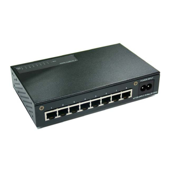
Page 6: Hardware Description
The physical dimensions of the 8-port 10/100TX internal power switch is 165mm(W) X 100mm(D) x 32.5mm(H). Front Panel The LED indicators are located on the upper cover of the switch. They provide a real-time indication of systematic operation status. LED Indicator The following table provides descriptions of the LED statuses and their meaning. -
Page 7: Rear Panel
100Base-TX connection. Auto MDI/MDI-X: Will detect if a straight-through cable is connected to a NIC or cascaded to a hub or switch, without the need to change the cable or connector. The maximum distance between the Switch and another device is 100 meters. -
Page 8: Installation
These footpads will help protect the Switch from shock/vibration. Mounting on the Wall The switch is designed so it can mount on the wall. The bottom of the switch has two cross hook holes for mounting the switch to a wall. Follow the steps below for wall mounting the switch. - Page 9 Connect the power cord to the power socket on the rear panel of the Switch. The other end of power cord connects to the power outlet. Check the power indicator on the upper panel to see if power is properly...
-
Page 10: Troubleshooting
If Link indicator does not light up after making a connection, you may check whether network interface (e.g., a network adapter card on the attached device), network cable, or switch port is defective or not. Be sure the cable is plugged into both the Switch and corresponding device. -
Page 11: Technical Specification
Technical Specification This section provides the specifications of the 8-port 10/100TX internal power switch. Standard Protocol Technology Transfer Rate Connector MAC Address Memory Buffer Backplane LED Indicator IEEE 802.3 10BASE-T Ethernet, IEEE 802.3u 100BASE-TX Fast Ethernet IEEE802.3x Flow Control and Back-pressure... - Page 12 10Base-T: 2-pair UTP Cat. 3, 4, 5 cable (100m), EIA/TIA-568 100-ohm STP (100m) Network Cable 100Base-TX: 2-pair UTP Cat. 5 cable (100m), EIA/TIA-568 100-ohm STP (100m) Dimension 165mm x 100mm x 32.5mm (L x W x H) Operating 0ºC to 45ºC (32ºF to 113ºF) Temperature Operating 5% to 95% (Non-condensing)
Need help?
Do you have a question about the MIL-S800I-V2 and is the answer not in the manual?
Questions and answers