Advertisement
Quick Links
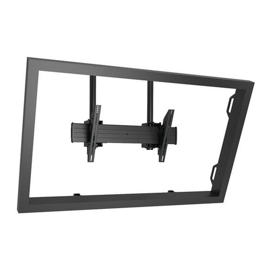
I N S T A L L A T I O N I N S T R U C T I O N S
XCM7000
(shown installed to 1-1/2" NPT
columns as example only)
Extra Large Dual Column Ceiling Mount
Spanish Product Description
German Product Description
Portuguese Product Description
Italian Product Description
Dutch Product Description
French Product Description
XCM7000
Advertisement

Related Manuals for CHIEF XCM7000


Summary of Contents for CHIEF XCM7000
- Page 1 I N S T A L L A T I O N I N S T R U C T I O N S XCM7000 (shown installed to 1-1/2" NPT columns as example only) Extra Large Dual Column Ceiling Mount...
-
Page 2: Important Safety Instructions
It is the installer’s responsibility to make sure the combined weight of all components located within the mounting system of the XCM7000 does not exceed a maximum weight capacity of 300 lbs (136.1 kg). -
Page 3: Installation Instructions
XCM7000 Installation Instructions DIMENSIONS TILT LOCKOUTS AT -7.6° -5° 0° 5° 10° 15° 20° 15.75 400.0 MAX VERTICAL MOUNTING PATTERN 31.98 812.2 MAX HORIZONTAL DIMENSIONS: INCHES [MILLIMETERS] 5° HOLE -5° HOLE DETAIL C DETAIL D DETAIL E SCALE 1 : 2 0°... - Page 4 XCM7000 Installation Instructions LEGEND Tighten Fastener Pencil Mark Apretar elemento de fijación Marcar con lápiz Befestigungsteil festziehen Stiftmarkierung Apertar fixador Marcar com lápis Serrare il fissaggio Segno a matita Bevestiging vastdraaien Potloodmerkteken Serrez les fixations Marquage au crayon Loosen Fastener Drill Hole Aflojar elemento de fijación...
-
Page 5: Tools Required For Installation
Installation Instructions XCM7000 TOOLS REQUIRED FOR INSTALLATION 3/32" 5/32" (included) 3/16" 1/2" or 13mm PARTS [Interface Bracket Hardware Kit] R (2) 10-24 x 1/4" A (8) C (6) D (6) B (6) M4x16mm M4x25mm M4x20mm M5x16mm S (2) Q (2) 3/32"... - Page 6 XCM7000 Installation Instructions INSTALLATION Repeat Steps 1 through 8 for remaining array head (FF). NOTE: The following procedure assumes that 2 UL Listed CPA or CMA ceiling plates (not included) and 2 extension Adjustment bolt columns (not included) have been properly installed following instructions provided with ceiling plates and extension columns.
- Page 7 Installation Instructions XCM7000 13. Repeat Steps 10 through 12 for remaining array head (FF), Partially fasten one 5/16" lock nut (AA) to each stud on assuring that second array head is approximately level with upper T-slot studs. first installed array head.
- Page 8 Figure 9 XCM7000 does not exceed a maximum weight capacity of 300 lbs (136.1 kg). Align the center of the interface bracket (KK) with center of screen.
- Page 9 Installation Instructions XCM7000 While supporting both sides of display, lower display onto Tilt center of ceiling mount, hooking top of interface brackets onto front of ceiling mount. (See Figure 11) NOTE: Two people will be required to adjust the tilt when the display is installed.
- Page 10 XCM7000 Installation Instructions OPTIONAL: Security OPTIONAL: Add padlock (not included) to each interface bracket to lock display to ceiling mount. (See Figure 14) Padlock (Optional) (Display not shown) Figure 14 Install back cover (GG) into four holes on back of both array heads (FF).
- Page 11 Installation Instructions XCM7000...
- Page 12 Europe A Franklinstraat 14, 6003 DK Weert, Netherlands P +31 (0) 495 580 852 F +31 (0) 495 580 845 Chief, a products division of Asia Pacific A Office No. 1 on 12/F, Shatin Galleria Milestone AV Technologies 18-24 Shan Mei Street...
Need help?
Do you have a question about the XCM7000 and is the answer not in the manual?
Questions and answers