Table of Contents
Advertisement
Quick Links
I N S T A L L A T I O N I N S T R U C T I O N S
Instrucciones de instalación
Installationsanleitung
Instruções de Instalação
Istruzioni di installazione
Installatie-instructies
Instructions d´installation
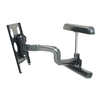
Large Flat Panel Wall Mount
Portuguese Product Description
Spanish Product Description
German Product Description
Italian Product Description
Dutch Product Description
French Product Description
PWR
Advertisement
Table of Contents

Related Manuals for CHIEF PWR


Summary of Contents for CHIEF PWR
- Page 1 I N S T A L L A T I O N I N S T R U C T I O N S Instrucciones de instalación Istruzioni di installazione Installationsanleitung Installatie-instructies Instruções de Instalação Instructions d´installation Large Flat Panel Wall Mount Spanish Product Description German Product Description Portuguese Product Description...
-
Page 2: Installation Instructions
WARNING: Failure to provide adequate structural strength Chief® is a registered trademark of Milestone AV Technologies. for the installation of this kit can result in serious personal All rights reserved. injury or damage to equipment! It is the installer’s... - Page 3 Installation Instructions TOOLS REQUIRED FOR INSTALLATION AND PARTS 5/32" 7/32" B (2) A (1) F (4) C (1) E (4) D (1) G (4) 5/16 x 2-1/2" H (4) .850x.385x.135...
-
Page 4: Mounting Pattern
Installation Instructions DIMENSIONS PRODUCT FEATURES WEIGHT CAPACITY 125 LBS NOTE: CUSTOM INTERFACE BRACKET Mounting Pattern NOT SHOWN. THE CUSTOM INTERFACE HEIGHT ADJUSTMENT BRACKET NEEDED FOR YOUR DISPLAY WILL ADD BETWEEN 1/2" AND 2" IN DEPTH AND MAY AFFECT LOCATION OF DISPLAY ,-15 / 2.5 / 0 ON THE MOUNT. -
Page 5: Mount Installation
7/32" x 4 INJURY OR DAMAGE TO EQUIPMENT! It is the installer’s responsibility to make sure the structure to which the PWR is being installed is capable of supporting five times the combined weight of the mount and all attachments. - Page 6 Installation Instructions Mount Lateral Position Adjustment The PWR is designed to allow up to 5" of right or left lateral adjustment after being mounted to the wall. This lateral adjustment can be used to more precisely position where the center of the display is located when installation is complete.
-
Page 7: Cover Installation
Installation Instructions Cover Installation To install channel covers: Install upper and lower wall channel covers (B) by tipping cover top down and positioning as shown in end view of figure below. (See Figure 5) Tap firmly across bottom of channels (B) to lock in place as shown in figure below. -
Page 8: Display Installation
Installation Instructions Display Installation WARNING: IMPROPER INSTALLATION CAN LEAD TO MOUNT FALLING CAUSING SEVERE PERSONAL INJURY OR DAMAGE TO EQUIPMENT. Displays can weigh in excess of 40 lbs (18.1kg). ALWAYS use two people and Remove pin proper lifting techniques when installing display. and nuts and move to lower holes. - Page 9 Installation Instructions (E) x 4 From Display Figure 8 ADJUSTMENTS Pitch Tension Adjustment To adjust display pitch tension: With display installed, tighten or loosen two screws, one on each side, using a 5/32” hex wrench. (See Figure 9) Check for desired tension. Repeat Steps 1 and 2 until desired tension is obtained.
-
Page 10: Swing Arm Tension Adjustment
Installation Instructions Roll Adjustment The PWR allows for the horizontal alignment (Roll)of the display (D) x 1 to be adjusted up to 2° right or left to level the display after installing. (C) x 1 To adjust Roll: Loosen the roll tension adjustment nut located on the back side of the faceplate assembly. - Page 11 Installation Instructions...
- Page 12 A 8401 Eagle Creek Parkway, Savage, MN 55378 P 800.582.6480 / 952.894.6280 F 877.894.6918 / 952.894.6918 Europe A Fellenoord 130 5611 ZB EINDHOVEN, The Netherlands Chief Manufacturing, a products P +31 (0)40 2668620 division of Milestone AV Technologies F +31 (0)40 2668615 Asia Pacific A Office No.
Need help?
Do you have a question about the PWR and is the answer not in the manual?
Questions and answers
tv keeps hitting bottom ledge of cabinet. how do i adjust