
Related Manuals for CHIEF XTM Series


Summary of Contents for CHIEF XTM Series
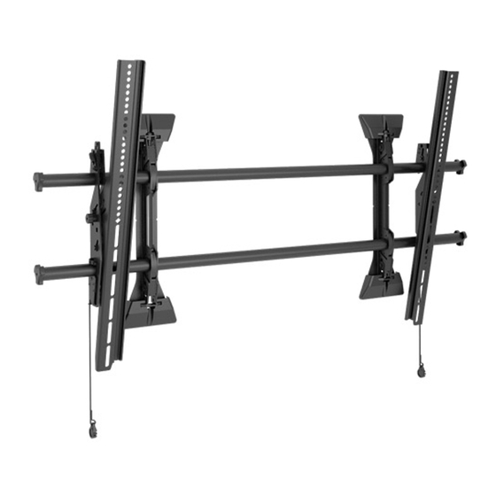
- Page 1 I N S T A L L A T I O N I N S T R U C T I O N S FUSION EXTRA LARGE HEIGHT ADJUST FLAT PANEL MOUNTS XSM/XTM Series...
-
Page 2: Installation Instructions
IMPORTANT ! : The XSM/XTM mount is designed to be mounted to: Chief® is a registered trademark of Milestone AV Technologies. All rights reserved. • a bare concrete wall with a minimum thickness of 8"... - Page 3 Installation Instructions XSM/XTM Series DIMENSIONS NOTES: MAX MOUNTING PATTERN IS 46" (1168.4 mm) WITHOUT REVERSING UPRIGHTS. MAX MOUNTING PATTERN IS 48.4" (1229.4 mm) WITH REVERSED UPRIGHTS. FOR RECESSED APPLICATIONS, MINIMUM VERTICAL LIFT FOR HOOK ENGAGEMENT IS .56"[14.2]. 20.6 MOUNT IS 2.23"[56.6mm] DEEP WHEN FLAT TO WALL.
- Page 4 XSM/XTM Series Installation Instructions LEGEND Tighten Fastener Pencil Mark Apretar elemento de fijación Marcar con lápiz Befestigungsteil festziehen Stiftmarkierung Apertar fixador Marcar com lápis Serrare il fissaggio Segno a matita Bevestiging vastdraaien Potloodmerkteken Serrez les fixations Marquage au crayon Loosen Fastener Drill Hole Aflojar elemento de fijación...
-
Page 5: Tools Required For Installation
XSM/XTM Series Installation Instructions TOOLS REQUIRED FOR INSTALLATION 7/32" (5.5mm) Wood Stud 5/16" (7.9mm) Concrete PARTS [A-K used on XSMU/XTMU Models Only] B (6) A (6) M6x25mm M6x16mm C (6) E (4) D (6) M8x20mm M8x50mm M8x30mm M (1) [Included with... - Page 6 XSM/XTM Series Installation Instructions INSTALLATION Center of screen The XTM and XSM have been designed to be mounted directly onto either a wood stud or concrete wall. The XTM has brackets which allow the display to be tilted. The XSM has static brackets 7-1/2"...
- Page 7 Installation Instructions XSM/XTM Series WARNING: ELECTRICAL SHOCK HAZARD! CUTTING OR DRILLING INTO ELECTRICAL CORDS OR CABLES CAN CAUSE DEATH OR SERIOUS PERSONAL INJURY! ALWAYS make certain area behind mounting surface is free of electrical wires and cables before drilling or installing fasteners.
- Page 8 XSM/XTM Series Installation Instructions Attaching Interface Brackets to Display Switching Interface Brackets (Optional) Align the center of the bracket with center of screen. If an installation situation makes adjusting the location of (See Figure 4) interface brackets necessary, there are several options.
- Page 9 Installation Instructions XSM/XTM Series If necessary, the tilt interface bracket knobs may be Adjust Velcro® pull strap (if necessary) so it does not switched to allow the interface brackets to be reversed. extend beyond bottom of screen. (See Figure 8)
- Page 10 XSM/XTM Series Installation Instructions XTM Model XSM Model NOTE: Push interface bracket tab all the way down so that the Proceed to Step 8 for XSM Model instructions. lower mounting slot is blocked. (See Figure 10) Hang top hook of interface brackets onto the top bar of the mount.
- Page 11 Installation Instructions XSM/XTM Series Adjusting Roll/Height of Wall Brackets Locking XSM Mount (Optional) NOTE: Add padlock (not included) to interface bracket tab to lock the The height adjust wall brackets allow adjustment of XSM mount. (See Figure 13) + 1/2".
- Page 12 Europe A Franklinstraat 14, 6003 DK Weert, Netherlands P +31 (0) 495 580 852 F +31 (0) 495 580 845 Chief, a products division of Asia Pacific A Office No. 1 on 12/F, Shatin Galleria Milestone AV Technologies 18-24 Shan Mei Street...
Need help?
Do you have a question about the XTM Series and is the answer not in the manual?
Questions and answers