Table of Contents
Advertisement
Quick Links
I N S T A L L A T I O N I N S T R U C T I O N S
Instrucciones de instalación
Installationsanleitung
Instruções de Instalação
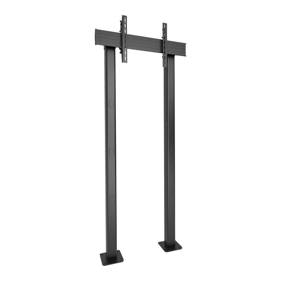
XBM1U
Extra Large Bolt Down Video Wall
XBM1U/XBM1UP
Istruzioni di installazione
Installatie-instructies
Instructions d´installation
XBM1UP
Spanish Product Description
German Product Description
Portuguese Product Description
Italian Product Description
Dutch Product Description
French Product Description
Advertisement
Table of Contents

Related Manuals for CHIEF XBM1U


Summary of Contents for CHIEF XBM1U
- Page 1 I N S T A L L A T I O N I N S T R U C T I O N S Instrucciones de instalación Istruzioni di installazione Installationsanleitung Installatie-instructies Instruções de Instalação Instructions d´installation XBM1U XBM1UP Extra Large Bolt Down Video Wall Spanish Product Description German Product Description Portuguese Product Description Italian Product Description...
-
Page 2: Important Safety Instructions
Exceeding the weight capacity can result in serious personal injury or damage to equipment! It is the installer’s responsibility to make sure the combined weight of each display and attached accessories mounted to the XBM1U/XBM1UP mount does not exceed 250 lbs (113.4 kg). -
Page 3: Installation Instructions
Installation Instructions XBM1U/XBM1UP DIMENSIONS XBM1U 21.23 539.2 17.00 431.8 33.00 838.2 250 LBS 36.00 XBM1UP 914.4 250 LBS 31.50 800.0 MAX MOUNTING PATTERN HEIGHT 21.23 539.2... - Page 4 XBM1U/XBM1UP Installation Instructions Bolt Down Dimensions BOTTOM VIEW FOR BOLT DOWN INSTALLATION 8.00 203.2 0.50 12.7 1.00 25.4 17.00 431.8 25.00 635.0 33.00 838.2...
- Page 5 Installation Instructions XBM1U/XBM1UP LEGEND Tighten Fastener Pencil Mark Apretar elemento de fijación Marcar con lápiz Befestigungsteil festziehen Stiftmarkierung Apertar fixador Marcar com lápis Serrare il fissaggio Segno a matita Bevestiging vastdraaien Potloodmerkteken Serrez les fixations Marquage au crayon Loosen Fastener Drill Hole Aflojar elemento de fijación...
-
Page 6: Tools Required For Installation
XBM1U/XBM1UP Installation Instructions TOOLS REQUIRED FOR INSTALLATION 1/2” (12.7mm) 3/8” (9.5mm) 3/16” (included) 1/8” (included) 5/32” (included) 3/8” (9.5mm) PARTS Hardware bag (letters correspond to letters on bag) D (4) E (4) B (4) C (4) A (4) 1/4” .750x.344x.5... -
Page 7: Assembly And Installation
(See Figure 2) WARNING: Do NOT install XBM1U mounts to any surface other than concrete! Concrete flooring must be at least 4" in thickness and NOT be covered with any other type of flooring material. -
Page 8: Rail Installation
XBM1U/XBM1UP Installation Instructions Column Add-On Installation (Optional) Use 5/16-18 x 4 1/2” button head cap screw (V), two 5/16” washers (X) and 5/16-18” lock nut (Z) to secure each clamp NOTE: Column add-ons (EE) are only required for extra large bracket (N) to column. -
Page 9: Display Installation
Installation Instructions XBM1U/XBM1UP Install two 5/16-18 x 3/4” button head flange screws (W) into Select screw diameter by examining hardware (A-C and F- the lower holes on each quick connect base (Q) to secure H) (6mm or 8mm) and comparing with mounting holes on rails to quick connect bases. - Page 10 XBM1U/XBM1UP mount does not exceed 250 lbs (113.4 kg). Use four 5/16-18 x 1/2” button head cap screws (U) to install each column cap (K) to each column. (See Figure 12) Hang interface brackets (S and T) to single display rail (R).
-
Page 11: Cable Management
Installation Instructions XBM1U/XBM1UP Adjustments Additional Cable Management Options Cables may be routed through tops of columns and out Height Adjustment through the back cable management hole. (See Figure 15) Use upper knob on back of interface brackets (S and T) to adjust the height of each display. - Page 12 Europe A Franklinstraat 14, 6003 DK Weert, Netherlands P +31 (0) 495 580 852 F +31 (0) 495 580 845 Chief, a products division of Asia Pacific A Office No. 918 on 9/F, Shatin Galleria Milestone AV Technologies 18-24 Shan Mei Street...
Need help?
Do you have a question about the XBM1U and is the answer not in the manual?
Questions and answers