Table of Contents
Advertisement
Quick Links
I N S T A L L A T I O N I N S T R U C T I O N S
Instrucciones de instalación
Installationsanleitung
Instruções de Instalação
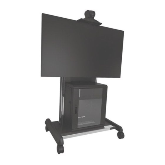
Height Adjustable Video Conferencing Cart
Istruzioni di installazione
Installatie-instructies
Instructions d´installation
Spanish Product Description
German Product Description
Portuguese Product Description
Italian Product Description
Dutch Product Description
French Product Description
XVAU
Advertisement
Table of Contents

Related Manuals for CHIEF XVAU


Summary of Contents for CHIEF XVAU
- Page 1 I N S T A L L A T I O N I N S T R U C T I O N S Instrucciones de instalación Istruzioni di installazione Installationsanleitung Installatie-instructies Instruções de Instalação Instructions d´installation Height Adjustable Video Conferencing Cart Spanish Product Description German Product Description Portuguese Product Description Italian Product Description Dutch Product Description French Product Description XVAU...
-
Page 2: Important Safety Instructions
It is the installer’s responsibility to make sure the combined weight of all components attached to the XVAU head assembly up to (and including) the display does not exceed 250 lbs (113.4 kg). Use with heavier televisions may result in instability... - Page 3 Installation Instructions XVAU DIMENSIONS 985.7 38.8...
- Page 4 XVAU Installation Instructions LEGEND Tighten Fastener Pencil Mark Apretar elemento de fijación Marcar con lápiz Befestigungsteil festziehen Stiftmarkierung Apertar fixador Marcar com lápis Serrare il fissaggio Segno a matita Bevestiging vastdraaien Potloodmerkteken Serrez les fixations Marquage au crayon Loosen Fastener Drill Hole Aflojar elemento de fijación...
-
Page 5: Tools Required For Installation
Installation Instructions XVAU TOOLS REQUIRED FOR INSTALLATION 3/8” 1/2” M5 (included) PARTS P (1) A (4) [Hardware bag] [Upright cover] B (2) [Interface upright] PA (8) PC (6) PB (6) M4x16mm M4x25mm M4x20mm PE (6) PD (6) PF (6) E (1) - Page 6 Lower shelf assembly onto head assembly, placing shelf Packaging Removal assembly hooks over extrusion. (See Figure 3) NOTE: The XVAU cart needs to be removed from the packaging pallet prior to camera shelf or display (column not shown installation. for clarity) Use 1/2”...
-
Page 7: Display Installation
XVAU head assembly up to (and including) the display does not exceed 250 lbs (113.4 Place uprights (B) on display, ensuring: (See Figure 6) kg). - Page 8 XVAU Installation Instructions Move latches on interface uprights to the “closed” position to secure display to head assembly. (See Figure 9) WARNING: Display may be very heavy! Ensure display may be safely lifted and maneuvered as required to install on cart.
-
Page 9: Cable Management
Installation Instructions XVAU Cable Management Route cables from display through inside of cart assembly attaching at cable management attachment points and/or accessory bracket as desired. (See Figure 13) NOTE: The following cable management options may vary based on type of display being mounted and user IMPORTANT ! : Route cables when display is at its preference. - Page 10 XVAU Installation Instructions Wrap cables around cable hooks (C) as desired. (See Figure 15) low point front view rubber bushing (C) x 4 Figure 15 Adjustments Height Adjustment Figure 17 Turn height adjustment knob clockwise to raise display. Pitch Adjustment...
- Page 11 It is the installer’s responsibility to make sure the combined weight of all components located within the XVAU rack box does not exceed 150 lbs (68 kg). Use with excessive weight may result...
- Page 12 XVAU Installation Instructions Always lock the wheels when the cart is not moving. Opening Rack Box Doors Check and tighten the hex nuts on the casters occasionally. Front Door (See Figure 21) These should be checked especially after use on uneven ground.
- Page 13 Installation Instructions XVAU Reverse Rack Box Door Fit spacer onto bottom pin and fit bottom pin into bottom mounting hole in rack. (See Figure 27) Turn upper door pin to release from locking tab and pull down to release door from rack and lift door from rack Turn upper pin to release from locking tab and pull down.
-
Page 14: Rear Cover Removal
XVAU Installation Instructions Remove screws, washers and bracket from door handle. Rear Cover Removal (See Figure 28) NOTE: The upper rear cover will need to be removed to route Flip the door handle. (See Figure 28) cables from display. The lower rear cover may also need to be removed depending on the application. - Page 15 Installation Instructions XVAU...
- Page 16 Europe A Franklinstraat 14, 6003 DK Weert, Netherlands P +31 (0) 495 580 852 F +31 (0) 495 580 845 Chief, a products division of Asia Pacific A Office No. 1 on 12/F, Shatin Galleria Milestone AV Technologies 18-24 Shan Mei Street...
Need help?
Do you have a question about the XVAU and is the answer not in the manual?
Questions and answers