Table of Contents
Advertisement
C575R OWNER'S MANUAL CONTENTS
1. INTRODUCTION ..............................................................................
2. SAFETY PRECAUTIONS ................................................................
3. LIST OF PARTS ...............................................................................
4. ASSEMBLE THE PRODUCT ..........................................................
STEP 1 Separate the Product from the Packaging..............................
STEP 2 Support the Frame .................................................................
STEP 3 Install the Rear Support..........................................................
STEP 4 Secure the Seat Carriage ......................................................
STEP 5 Secure the Seat Bottom and Back .........................................
STEP 6 Install the Pedestal and Pedals...............................................
STEP 7 Install Covers ..........................................................................
STEP 8 Move the Product ..................................................................
STEP 9 Level the Bike ........................................................................
STEP 10 How to Connect the Ground Wire .........................................
5. UNDERSTAND THE C575R DISPLAY ...........................................
DISPLAY Overview ..............................................................................
DISPLAY Specifications .......................................................................
DISPLAY Windows ............................................................................... 24
DISPLAY Keys ...................................................................................... 24
6. OPERATE THE PRODUCT .............................................................
OPERATION Quick Start .....................................................................
OPERATION Start a Workout Program ...............................................
OPERATION Display ...........................................................................
OPERATION Cool Down .....................................................................
OPERATION Workout Programs .........................................................
OPERATION User Preferences and Component Versions...................
7. ABOUT HEART RATE DETECTION ................................................
HEART RATE Telemetry ......................................................................
HEART RATE Contact .........................................................................
8. GUIDELINES FOR EXERCISE .......................................................
9. ACCESSORIES ...............................................................................
10. MAINTENANCE .............................................................................
MAINTENANCE Messages .................................................................. 36
MAINTENANCE Lubrication ................................................................
MAINTENANCE Schedule ...................................................................
MAINTENANCE Task List (Cycles) ......................................................
MAINTENANCE One-Year Maintenance Log ......................................
MAINTENANCE Electronics Block Diagram ........................................
2
3
7
9
9
10
11
13
15
17
19
20
21
22
23
23
24
26
26
26
27
28
28
31
32
32
32
33
34
36
36
37
38
39
40
Advertisement
Table of Contents

Related Manuals for SportsArt Fitness C575R


Summary of Contents for SportsArt Fitness C575R
-
Page 1: Table Of Contents
STEP 7 Install Covers ................STEP 8 Move the Product ..............STEP 9 Level the Bike ................ STEP 10 How to Connect the Ground Wire ......... 5. UNDERSTAND THE C575R DISPLAY ........... DISPLAY Overview ................DISPLAY Specifications ............... DISPLAY Windows ................24 DISPLAY Keys .................. -
Page 2: Introduction
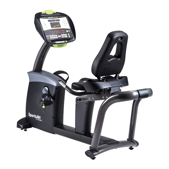
1. INTRODUCTION Congratulations on your purchase of one of the finest exercise products on the market today, the C575R recumbent exercise cycle Constructed of high quality materials and designed for years of reliable usage, this product was made to become an integral part of your commercial fitness venue. -
Page 3: Safety Precautions
2. SAfETy PRECAUTIONS Your SportsArt bike was designed and built for optimum safety. However certain precautions apply whenever you use your bike. Please read the entire manual before assembly and operation. Also, please note the following safety precautions: ● Please read the instructions carefully and install the bike as instructed. ●... - Page 4 2. SAfETy PRECAUTIONS (CONTINUED) Caution If you feel any pain or abnormal sensation, STOP YOUR WORKOUT and consult your physician immediately. Work within your recommended exer- cise level. DO NOT work to exhaustion. Before beginning any exercise program, you should consult with your doc- tor.
- Page 5 2. CONSIgNES DE SéCURITé...
- Page 6 2. CONSIgNES DE SéCURITé (SUITE)
-
Page 7: List Of Parts
3. LIST Of PARTS Assembly Parts Qty. No. Qty. Name Name Pedestal and display Seat carriage Main frame and body Seat back Pedals Seat bottom Handlebars (withcontact Support covers heart rate detection) Rear frame cover A11 Hardware kit Rear support... - Page 8 Components in the Hardware Kit Name Qty. Specification Notes L-shaped Allen wrench L-shaped Allen wrench Double open-end wrench (12*15) Screwdriver handle Green Screwdriver bit Flat and Phillips Components on the Product Name Specification Notes Mushroom top inner hex screw M8*L15 Flat washer D15.5*d8.1*t0.5 Inner hex screw...
-
Page 9: Assemble The Product
4. ASSEMBLE THE PRODUCT Follow instructions below to assemble this product. Note that in this manual the words “left” and “right” are used to refer to the product and its parts. As such, these designations correspond to the “left” and “right” sides of a person in position to exercise on this product. -
Page 10: Step 2 Support The Frame
STEP 2 Support the frame Before assembling the bike, please insert a piece of corrugated cardboard as shown to lift the main frame approximately 60 mm (about 2 11/32 inch). This will aid in the installation of the rear support. -
Page 11: Step 3 Install The Rear Support
STEP 3 Install the Rear Support... - Page 12 STEP 3 Install the Rear Support (Continued) Install the rear support as shown in steps (a) through (b) below. (a) Remove screws from the rear support (A6). Insert the stem of the rear support (A6) into the main frame (A2) as shown. (b) First, loosely secure screws (21) into the top of the main frame.
-
Page 13: Step 4 Secure The Seat Carriage
STEP 4 Install the Seat Carriage Secure the seat carriage and handlebars as shown in steps (a) through (d). (a) First, remove screws (22) from the rear support (A6). Then insert the end of the seat carriage (A7) into its mount on the rear support (A6). (b) Loosely secure screws (22) in area A before loosely securing screws in area B. - Page 14 STEP 4 Secure the Seat Carriage (Continued) (e) Push the seat carriage (A6) toward the rear support. Then fully secure screws in areas A, B and C in sequence, starting with those in area A. Connect the seat carriage (A7) cable to the connector in the seat post of the main frame (A2).
-
Page 15: Step 5 Secure The Seat Bottom And Back
STEP 5 Secure the Seat Bottom and Back... - Page 16 STEP 5 Secure the Seat Bottom and Back (Continued) Follow steps (a) through (c) to install the seat bottom and seat back. (a) Remove screws (24) from the seat bottom (A9). Place the seat bottom (A9) onto the seat carriage (A7). Align the screw holes. From the bottom, secure the screws (24) into place.
-
Page 17: Step 6 Install The Pedestal And Pedals
STEP 6 Install the Pedestal and Pedals... - Page 18 STEP 6 Install the Pedestal and Pedals (Continued) Follow steps (a) through (c) to install the pedestal assembly and the pedals. (a) Remove the front cover (28) and screws (26) from the main frame (A2). Connect the cable from the pedestal (A1) into the connector in the main frame (A2).
-
Page 19: Step 7 Install Covers
STEP 7 Install Covers Follow steps (a) through (b) to install the rear frame cover and the seat post covers. (a) Remove screws (27) from the main frame (A2). Slide the rear frame cover (A5) from the back toward the front on the main frame (A2). Use screws (27) to secure the cover into place. -
Page 20: Step 8 Move The Product
STEP 8 Move the Product Lift the rear support and push, rolling the bike into place for use. -
Page 21: Step 9 Level The Bike
STEP 9 Level the Bike For the user’s safety and the proper functioning of the product, this bike must sit level on a flat floor. If necessary, adjust the levelers by following instructions (a) through (c) below. (a) Loosen the leveler nut. (b) Rotate the leveler foot downward so it firmly touches the floor. -
Page 22: Step 10 How To Connect The Ground Wire
STEP 10 How to Connect the ground Wire Note: A ground wire and the following instructions are required by European safety standards. The ground wire is not required by North American safety standards. Installation instructions: Please use screws and washers to secure one end of the ground wire to the product frame as shown and the other end to the building electrical ground. -
Page 23: Understand The C575R Display
5. UNDERSTAND THE C575R DISPLAy DISPLAy Overview The C575R recumbent cycle is designed for user convenience. With better feedback about your workout, you get better results. The following explains the display key and window functions. Please read this manual, understand the display functions, and thereby get optimum enjoyment and benefit from this product. -
Page 24: Display Specifications
DISPLAy Specifications ● Workout level (resistance level): 1 - 40 ● METS: 0.0 - 99.0 ● Time: 0:00 - 300:00 ● Distance: 0.00 - 9999 km or mile ● Calories: 0.0 - 9999 kcal ● RPM: 5 – 150 (Range shown) ●... - Page 25 DISPLAy Keys (Continued) fAT BURN – This workout program provides 1 - 20 different difficulties to select from. fIT TEST – Press this key to enter a FIT TEST program and start the fitness test. CUSTOM HR – This heart rate control program allows you to set your own target heart rate.
-
Page 26: Operate The Product
DISPLAy Keys (Continued) CHANgE DISPLAy – This key controls the exercise feedback window, which has two rows: The top row shows CALORIES, LEVEL, TIME, DISTANCE; the bottom row shows RPM, METS, SPEED, HUMAN WATTS. Corresponding LEDs light to indicate the active row of exercise feedback. Press the CHANGE DISPLAY key to toggle between top and bottom feedback row views. -
Page 27: Operation Display
OPERATION Start a Workout Program (Continued) setting and proceed to input your age. Or press QUICK START key to start this program right away with default age and weight. ● The DISTANCE setting range is from 0.1 to 99.9 miles or kilometers, with a default value 2.0 miles (3.0 kilometers). -
Page 28: Operation Cool Down
OPERATION Display (Continued) ● Switch program is not allowed during FIT TEST program. OPERATION Cool Down Once the workout goal (time, distance, or calorie expenditure) has been obtained, the product will enter a two-minute cool down period. The display will count down from two to zero. When the countdown reaches zero, the cool down period will end. - Page 29 OPERATION Workout Programs (Continued) RANDOM This program provides a near infinite number of randomly generated workouts. A new workout illustration appears each time the RANDOM key is pressed. fAT BURN In this program, there are 1-20 different difficulty levels to select from. During program setting, before entering program mode, you must first select the STAGE, range from 1 - 20 (default value is STAGE 5).
- Page 30 OPERATION Workout Programs (Continued) CARDIO/WEIgHT LOSS/CUSTOM HR In these heart rate control programs, the resistance level will automatically change to keep the exerciser’s pulse at the optimum rate for achieving his or her fitness goals. Target heart rates are calculated based on a standard “maximum” heart rate for the exerciser’s age.
-
Page 31: Operation User Preferences And Component Versions
OPERATION User Preferences and Component Versions Basic settings determine units of measure and show total distance and time, along with display and drive board program version numbers. To access this information, at the startup banner screen, hold the CHANGE DISPLAY key for two seconds. -
Page 32: About Heart Rate Detection
7. ABOUT HEART RATE DETECTION Heart rate detection functions are selected at the time of purchase. Not every product has every type of heart rate detection. The following explains factors that influence the performance of two of the most common types of heart rate detection devices. -
Page 33: Guidelines For Exercise
Note that in dry areas in particular, static electricity can interfere with unit operation and shock people. To discharge static electricity from your body, touch something else before touching metal on the product. 8. gUIDELINES fOR EXERCISE HOW HARD SHOULD I EXERCISE? Studies show that to benefit from aerobic exercise, people need to maintain a certain heart rate during their workouts. -
Page 34: Accessories
9. ACCESSORIES There are accessories attached to this console; some are standard and some are optional. The following explains the details of each accessory and its function. USB CHARgER (Standard) The USB charger will provide 5V 500mA voltage for the smart phone or other devices charging. - Page 35 9. ACCESSORIES (CONTINUED) Entertainment Cap The functions of the Entertainment Cap of the display: (a) RFID member card slot: work with both optional SAFitDirector and ECOFIT member cards. (b) Bluetooth connection button: press this button to pair or unpair the smart phone SAFitDirector App.
-
Page 36: Maintenance
10. MAINTENANCE Maintenance topics are presented below in the following order: error messages, lubrication the seat carriage, maintenance schedule, task list, one-year maintenance log, and electronics block diagram. MAINTENANCE Messages The following message can appear on this product for diagnostic purposes. - - - - (four flashing lines) - Indication: The unit is entering the energy saving mode. -
Page 37: Maintenance Schedule
MAINTENANCE Schedule Area Day Week Month Quarter year Notes Exterior Clean Inspect and Screws secure loose parts Seat Wipe clean with back and a slightly damp bottom towel. Inspect and Pedals secure loose parts Seat Apply silicone carriage lubricant rail... -
Page 38: Maintenance Task List (Cycles)
MAINTENANCE Task List (Cycles) Like cars, fitness products require maintenance. Regular maintenance extends product life, and failure to maintain products can void the manufacturer’s warranty. Copy the maintenance log sheet, and record maintenance work for each fitness product. Daily tasks 1. -
Page 39: Maintenance One-Year Maintenance Log
MAINTENANCE One-year Maintenance Log Facility:_______________________ Supervisor:____________________ Product model number:__________ Serial number:_________________ Start date: ____________________ End date:_____________________ Daily Tasks Weeks 1-7 Weeks 8-14 Weeks 15-21 Week 22-28 Completed Daily Tasks Week 29-35 Week 36-42 Week 43-49 Week 50-52 Completed Weekly Tasks Weeks 1-7 Weeks 8-14 Weeks 15-21 Weeks 22-28... -
Page 40: Maintenance Electronics Block Diagram
MAINTENANCE Electronics Block Diagram Bluetooth Connection Key Control Board USB Board CSAFE Board HRC Board [Option] Key Board Contact HTR Plates :Connector HTR Board :Converge iPod Audio Board Head Phone Board HTR Hub Board Model No. Board Speed Sensor C575 Drive Board Fuse ○...
Need help?
Do you have a question about the C575R and is the answer not in the manual?
Questions and answers