Table of Contents
Advertisement
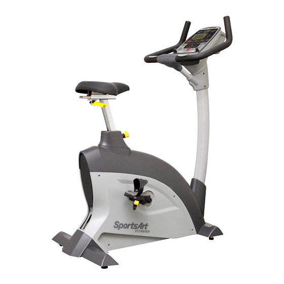
SPORTSART C532U UPRIGHT BIKE
TABLE OF CONTENTS
1. INTRODUCTION................................................................................................
2. IMPORTANT SAFETY PRECAUTIONS.............................................................
3. LIST OF PARTS................................................................................................
4.
ASSEMBLING YOUR BIKE
STEP1 Rear Support and Cover Installation....................................................
STEP3 Handlebar and Cover Installation.........................................................
STEP4 Pedal Installation..................................................................................
STEP6 Product Placement ..............................................................................
STEP7 Leveling the Product............................................................................
DISPLAY Overview.............................................................................................
DISPLAY Windows.............................................................................................
DISPLAY Keys....................................................................................................
DISPLAY Specifications.....................................................................................
6.
OPERATION Quick Start....................................................................................
OPERATION Start..............................................................................................
OPERATION Cool Down....................................................................................
OPERATION Workout Programs........................................................................
7. INTERNAL SETTINGS.......................................................................................
HEART RATE Telemetry.....................................................................................
CONTACT Heart Rate........................................................................................
HOW HARD SHOULD I EXERCISE?................................................................
HOW LONG SHOULD I EXERCISE?................................................................
HOW OFTEN SHOULD I EXERCISE?..............................................................
10. MAINTENANCE CHECK LIST..........................................................................
11. WIRING SCHEMATIC......................................................................................
..............................
..........................
..........................................................
.
.........................................................
...............................................
....................................................
1
2
6
9
11
14
16
17
18
19
.........
20
..
22
23
24
24
25
26
26
28
29
32
33
33
35
35
35
36
38
Advertisement
Table of Contents

Subscribe to Our Youtube Channel
Related Manuals for SportsArt Fitness C532U


Summary of Contents for SportsArt Fitness C532U
-
Page 1: Table Of Contents
STEP6 Product Placement ................STEP7 Leveling the Product................STEP8 Adjusting the Seat Position ..............STEP9 How To Connect The Ground Wire ............ 5. UNDERSTANDING THE C532U DISPLAY CONSOLE DISPLAY Overview..................... DISPLAY Windows..................... DISPLAY Keys....................DISPLAY Specifications..................OPERATING THE C532U EXERCISE BIKE OPERATION Quick Start.................. -
Page 2: Introduction
Congratulations on purchasing one of the finest pieces of exercise equipment on the market today, the C532U exercise bike. Constructed of high quality materials and designed for years of trouble-free usage, the C532U exercise bike will become an integral part of your fitness regimen. -
Page 3: Important Safety Precautions
IMPORTANT SAFETY PRECAUTIONS... -
Page 7: List Of Parts
LIST OF PARTS Assembly Parts Name Qty No. Description Pedestal Seat bottom Handlebar mount upper and Left/right pedals lower cover Rear support Handlebar Rear support cover Pedestal cover Hardware kit Main frame and body... - Page 8 Hardware Kit Name Name Specification Specification Notes Notes Screw socket M5*L12 Mushroom top Phillips screw BW5 3/16 Serrated washer (M5) L-shaped Allen wrench (M6) L-shaped Allen wrench (13*15) Double open-end wrench green Screwdriver handle Screwdriver bit Phillips and flat Components on the Product Part Name Specification M8*L20...
- Page 9 Follow steps A, B, and C to flatten the cardboard box and place the body of the bike on the flattened cardboard. A. First, remove the parts, and cut the four corners of the box to flatten them. B. Lift the front end of the box and remove the Styrofoam. C.
-
Page 10: Step1 Rear Support And Cover Installation
ASSEMBLING YOUR EXERCIS E BIKE STEP 1 Rear Support and Cover Installation... - Page 11 1. Follow steps (a~d) below to install the rear support and its cover. (a) Insert screw sockets (21) into the rear support (A8). Then remove screws (31) from the rear support (A8). (b) Use these screws (31) to secure the rear support (A8) to the main frame (A5). (c) Align the support cover (A9) with the left and right side covers.
-
Page 12: Step2 Pedestal Installation
STEP 2 Pedestal Installation... - Page 13 2. Follow steps (a~f) below to secure the pedestal onto the main frame. (a) First, remove screws (32) from the lower part of the pedestal (A1). Note: Areas A and B have elongated holes; Area C has round holes. (b) Insert the pedestal cover (A4) onto the pedestal (A1) as shown. (c) Insert the pedestal (A1) onto the pedestal base on the main frame (A5), aligning it with hole A.
- Page 14 (d) Once screws are loosely in place, lower the pedestal into place until B and C holes come into alignment. (e) First secure screws (32) in position C. Then secure screws in positions A and B. ( ) Connect cables at the pedestal base and tuck extra cabling into the pedestal for safety.
-
Page 15: Step3 Handlebar And Cover Installation
STEP 3 Handlebar and Cover Installation 3. Follow steps (a~e) below to secure the handlebar and handlebar mount upper and lower covers. (a) Remove screws (33) from the handlebar (A3) as shown. (b) Remove screws (34), and disconnect upper and lower mount covers (A2) from each other. - Page 16 (c) Hold the handlebar (A3) onto its mount on the pedestal, and (A1) secure the handlebar mounting screws. (d) After securing handlebar mount screws, connect wires in the pedestal and handlebars. Then tuck wires into the handlebar for safety. (e) Connect handlebar mount upper and lower covers (A2) onto the product, and secure screws (34).
-
Page 17: Step4 Pedal Installation
STEP 4 Pedal Installation 4. Be very careful in securing pedals to the pedal cranks. Otherwise, pedals and left and crank threads can easily become stripped and must be replaced. Note that right side designations for parts correlate to the exerciser's left and right sides as he or she exercises on the product. -
Page 18: Step5 Seat Installation
STEP 5 Seat Installation 5. First, remove nuts (35) from the seat bottom (A6). Set the seat bottom in place and secure it with the nuts (35). -
Page 19: Step6 Product Placement
STEP 6 Product Placement 6. Follow steps (a~c) to install the product in place for use. (a) Stand in front of the unit. Place one foot in front of the wheel. (b) Hold onto handlebars with both hands. (c) Press the handlebars down, placing the unit at a slant. Then roll the bike off the cardboard and into place for use. -
Page 20: Step7 Leveling The Product
Leveling the Product STEP 7 7. Test whether the product wobbles in use. It should rest flat on the floor. If necessary, follow steps (a,b,c) to level the unit. (a) Loosen the leveler nut. (b) Rotate the leveler foot so that it touches the floor. (c) Then secure the leveler nut against the product frame to secure this position. -
Page 21: Step8 Adjusting The Seat Position
Adjusting the Seat Position STEP 8 8-1. Follow steps (a~c) to adjust seat height. (a) Turn the seat adjustment knob counterclockwise. Then pull the knob. (b) Use your hand to adjust the seat position up or down. (c) When the seat is in the desired position, release the knob. Then turn the knob clockwise to lock the seat into place. - Page 22 8-2. Follow steps (d~f) to adjust seat fore and aft placement. (d) Press the fore/aft adjustment lever downward to release the seat. (e) Use your hand to move the seat fore or aft as desired. (f) Lift the fore/aft adjustment lever upward to secure this position.
-
Page 23: Step9 How To Connect The Ground Wire
STEP 9 How To Connect The Ground Wire Note: The installation of a ground wire is required by European safety standards. The ground wire is not required by North American safety standards. Ground wire installation: Use a screw to secure one end of the ground wire to the product frame as shown. -
Page 24: Understanding The C532U Display Console
UNDERSTANDING THE C532U DISPLAY CONSOLE DISPLAY Overview The C532U exercise bike is designed for user convenience. With better feedback about your workout, you get better results. The following explains the display key and window functions. Please read this manual, understand the display functions, and thereby get optimum enjoyment and benefit from this product. -
Page 25: Display Windows
DISPLAY Windows ■ - 65% HR TARGET shows the optimum heart rate zone for weight loss. ■ - HEART RATE shows actual heart rate. ■ - 80% HR TARGET shows the optimum heart rate for cardio conditioning workouts. ■ - WORKOUT ILLUSTRATION shows workout profiles and workout prompts. -
Page 26: Display Specifications
DISPLAY Specifications ˙ WORKOUT LEVEL (resistance): 1 ~ 20 ˙ : TIME: 00 ~ 99 59; setting range: 5:00 ~ 99:00. (After 99:00, 0 appears.) ˙ DISTANCE: 0.01 ~ 9999 Km/Mile ˙ CALORIES: 0 ~ 9999 K-CAL ˙ CAL/Hr (calories per hour): 0.0 ~ 999.9 K-CAL ˙... -
Page 27: Operating The C532U Exercise Bike
OPERATING THE C532U BIKE There are two ways to start operating the C532U bike. Either press the QUICK START key or press the START key. QUICK START mode allows you to start exercising immediately, without the benefit of a user ID. START mode allows you to use a user ID. - Page 28 Press WORKOUT LEVEL keys to toggle to different user IDs. <▲> <▼> Then press the ENTER key to confirm your choice. If you do not press any key, "SELECT YOUR ID PRESS ENTER OR PRESS QUICK START" appears. TO ESTABLISH AN ALPHA-NUMERIC USER ID Once a user ID has been established, you can personalize that user ID by giving it an alpha-numeric user name.
-
Page 29: Operation Cool Down
Note that the age setting range is 10 to 99 years; the default age is 35 years old. The weight setting range is 66 to 450 lb/30 to 205 kg. The default weight setting is 165 lb/75 kg. Once user settings are established, the display prompts you to select a workout program and time. -
Page 30: Operation Workout Programs
OPERATION Workout Programs The following explains features of the workout programs. TRACK The track workout program allows you to manually control resistance. It could be “ ” called manual. HILL The HILL program contains three hill patterns to choose from. A different pattern appears each time the HILL key is pressed: HILL-1, HILL-2, HILL-3. - Page 31 WEIGHT LOSS AND CARDIO WEIGHT LOSS and CARDIO workouts are heart rate control programs. In heart rate control programs, resistance automatically adjusts to keep your heart rate within an optimum range for your exercise goals. Target heart rates are calculated as follows: 1.
- Page 32 Please note the following characteristics of the ZONE TRAINER program: ˙ This program can only be activated from another workout program. (Pressing the ZONE TRAINER key before you start to exercise does not activate this program.) It also requires reception of a heart rate signal. ˙...
-
Page 33: Internal Settings
Internal settings determine basic feedback parameters, for example, units of measure. To access internal settings, at the start up banner screen, "SPORTSART- C532U", press and hold the CHANGE key for three seconds. Follow steps below to change and view internal settings. -
Page 34: About Heart Rate Detection And Presentation
ABOUT HEART RATE DETECTION AND PRESENTATION Heart rate detection functions are optional and may not be included in your particular model. If your bike is equipped with these functions, please note the following information. HEART RATE Telemetry The word "telemetry heart rate" refers to the detection of the heart rate, usually via a strap worn on the exerciser's chest and transmitted over the air for reception by a receiver built into the product. - Page 35 4.The vibration of treadmills at speeds over 4 mph/6.4 kph makes heart rate detection difficult. Also, if your hands move, heart rate detection becomes difficult. SUGGESTIONS For better heart rate detection, keep hands in one place on the contact plates. Or wear a telemetry heart rate strap on your chest.
-
Page 36: Guidelines For Exercise
GUIDELINES FOR EXERCISE HOW HARD SHOULD I EXERCISE? Studies show that to achieve the benefits of aerobic exercise, it is necessary to work within your training zone. Your training zone depends on your age and level of fitness. The above chart indicates the recommended Heart Rate training zones (darkened area of the chart). -
Page 37: Maintenance Check List
MAINTENANCE CHECK LIST Like cars, fitness products require maintenance. Regular maintenance extends the life of your fitness product, and failure to provide regular maintenance will void your warranty. Copy the maintenance log sheet and record maintenance work. DAILY TASKS 1. Check the product for proper operation and user safety. Make sure that pedal straps, pedals, cranks and other parts are secure and safe for operation. - Page 38 ONE- YEAR MAINTENANCE RECORD SHEET Facility Name: Maintenance Supervisor: Product Serial Number: Start Date: End Date: Daily Tasks Week1 Week2 Week3 Week4 1.Safe 2.Clean Daily Tasks Week5 Week6 Week7 Week8 1.Safe 2.Clean Week9 Week10 Week11 Week12 Daily Tasks 1.Safe 2.Clean Month 10-12 Months 1-3 Months 4-6...
-
Page 39: Wiring Schematic
WIRING SCHEMATIC C532U CON2 CTL Board HTR BOARD CON1 Telemetry heart rate receiver CON3 board Battery charger DRIVER BOARD Alternator Speed Sensor Electro-magnet Battery Your Authorized SPORTS ART Distributor...
Need help?
Do you have a question about the C532U and is the answer not in the manual?
Questions and answers