
Subscribe to Our Youtube Channel
Related Manuals for SportsArt Fitness C575R


Summary of Contents for SportsArt Fitness C575R
- Page 1 C575R Repair Manual (Electronics)
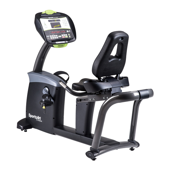
- Page 2 1-1. C575R Product pictures 1-1-1...
- Page 3 1-2. Display -C575R 1-2-1...
- Page 4 1-3.Component Placement- C575RDisplay USB board Display Polar wireless board Program board 1-3-1...
- Page 5 1-3.Component placement - C575R lower frame Drive board Alternator Model no. board Battery 6V Battery Speed sensor Electro-magnet 1-3-2...
- Page 6 1-3.Component placement - C575R Lower frame Drive board Alternator Electro-magnet 1-3-2...
-
Page 7: C-Safe Board
1-4. Block diagram -C575R Display USB Board keypad Board C-SAFE Board HR receiver Electronic Charge Magnet Alternator Speed Sensor Drive Battery Board HTR board Model board Sensor-L Transfer board Sensor-R 1-4-1... - Page 8 1-5.Block diagram-C575R 1-5-1...
- Page 9 1-5.Connections - C575R display To USB board To drive board To fan To drive board To USB board & CSAFE board To key pads Program board To USB board To POLAR board To HTR board 1-5-2...
- Page 10 1-5. Connections -C575R Display USB board To drive board Bluetooth pair To drive board button To program board (upgrade program software) 1-5-2...
- Page 11 1-5. Connections -C575R Drive board To drive board To electro-magnet To Speed sensor To model no. board To HTR handle To alternator & battery charger To battery To battery fuse 1-5-3...
- Page 12 1-6. Display board indicator LEDs -C575R display LED16 POWER LED18 COMM indicator 1-6-1...
- Page 13 1-6.Drive board indicator -C575R/U LED 2 Charger Lit = charging F2 battery fuse LED 3 VBB Lit= VBB voltage LED 6 VCC power Lit = VCC power F1alternator fuse LED 4 HTR (C575R) HTR signal indicator LED 1 CLK Speed sensor indicator...
- Page 14 1-7. Electronic component specification -C575R Description Note Specification AC alternator Main power Rechargeable Battery 6V *2 Battery Self-charging or charging from the outside power source Resistance control Electro-magnetic (current control) LEVEL 1 – LEVEL 40 Resistance range Speed sensor Infrared sensor...
- Page 15 2-1.Troubleshooting -C575R Faulty item Description Inspect and test procedures Suggesting replacement parts No power Display is not lit up 1.Check all wire connections 1. Drive board alternator fuse while pedaling the bike 2.Check drive board alternator fuse 2. Drive board 3.
- Page 16 No/bad contact No/bad HTR heart rate 1. Make sure palms are holding on the sensors. 1. HTR board heart rate signal 2.Check the HTR board signal status 2. HTR sensor reception 3.Check HTR wiring problem 3. HTR wiring Total distance Kph/mph/total 1.
- Page 17 Troubleshooting Model: C575R Malfunction item: Product will not turn on -alternator POWER1 Circumstance: Start pedaling, display will not turn on Possible causes: 1.Bad wire connections 2.Alternator fuse brunt 3.Bad drive board 4.Bad control board Troubleshooting: 1.Check the alternator fuse 2.Check all wire connections 3.Check drive board LED indicator or replace drive board...
- Page 18 Troubleshooting Model: C575R Malfunction item: Product will not start – rechargeable battery Circumstance: Press <Quickly start> on the console and no response Possible causes: 1.Bad wire connections 2.Wiring problem with rechargeable battery LED1 Troubleshooting: 1.Check the drive board and rechargeable battery fuse 2.Measure the battery voltage, it should be above 6V * 2...
-
Page 19: Troubleshooting
Troubleshooting Model: C575R Malfunction item: No RPM display Circumstance: There is no RPM display while pedaling the bike Possible causes: 1.Bad wire connections 2.Bad speed sensor signal Troubleshooting: 1.Check to see if the distance between sensor and its sticker < 5mm 2.Clean speed sensor... - Page 20 Troubleshooting Model: C575R Malfunction item: No resistance Circumstance: No resistance while pedaling the bike Possible causes: 1. No RPM signal on display 2. Bad drive board Troubleshooting: 1.Check CLK indicator on the drive board 2.Check all wire connections 3.Check alternator voltage 4.Measure the resistance voltage output or replace the drive board.
- Page 21 Troubleshooting Model: C575R Malfunction item: Resistance voltage output too much or not enough Circumstance: Resistance voltage output too much or not enough Possible causes: 1.Bad drive board Troubleshooting: 1.Measure the drive board voltage Blue-blue 2.Check flywheel if the voltage is normal Level Voltage(V)...
-
Page 22: Heart-Rate Receiver
Troubleshooting Model: C575R Malfunction item: Bad telemetry heart rate reception Circumstance: Bad telemetry heart rate reception Possible causes: 1.Telemetry transmitter battery too low 2. Bad HR receiver board 3. Interference issue, such as lights, speakers Troubleshooting 1.Replace the transmitter battery 2. - Page 23 Troubleshooting Model: C575R HTR board LED indicator Malfunction item: Bad HTR signal Indicator Name Description LED1 Telemetry Flashes to indicate incoming telemetry signal Circumstance: Holding to HTR and the reading is incorrect LED2 HTR contact Lights to indicate hands on the contact plates Possible causes: 1.
- Page 24 Troubleshooting Model: C575R Key pads Malfunction item: bad keys – soft key pads Circumstances: No response when pressing keys Possible causes: 1.Bad membrane key pads Troubleshooting: 1.Replace membrane key pads Display board Membrane Key pad Membrane Key pad 3-5-1...
- Page 25 Troubleshooting Model: C575R Tact switches Malfunction item: Bad key - display Circumstance: No response while pressing the display keys, such as pressing <STOP>,LEVEL <▲> , LEVEL <▼> Possible causes: 1. Bad display tact switches 2. Bad switch cushion placement Troubleshooting: 1.Check switch cushions 2.
- Page 26 Troubleshooting Model: C575R Malfunction item: Fan does not operate correctly Circumstance: 1.Press the fan key & fan is not responding Possible causes: 1.Bad control board 2.Bad fan wire connections or bad fan motor Troubleshooting 1.Check the fan key and wire connections 2.Measure control board fan voltage...
-
Page 27: Other Items
Other items Model:C575R Items:Other function descriptions Description: 1.Energy saving mode No key pressing or no rpm for more than 15 minutes in anytime, the product will enter energy saving mode. The display will show “----“ to indicate the mode. 2.Power On A). - Page 28 Other items Model: C575R Item: Error messages Description: 1. ERROR_8_1_ : Communication malfunction during power on 2. ERROR_8_2_ : Communication malfunction during normal operation 3-8-1...
- Page 29 Other items Model: C575R Item: KPH/MPH switch, total distance, total time and software version display Method: 1. Press <CHANGE DISPLAY” for 3 seconds to get into user reference and setting mode A. English and Metric setting The display will show “UNIT-MPH” for English setting or “UNIT-KPH” for metric setting. Press INCLINE <▲>...
- Page 30 Other items Model: C575R Item: Language setting Description: How to set up the language preference, such as German, French… Method: 1. Press <CHANGE DISPLAY> for 3 seconds to enter user preference and setting mode. Continuing pressing <ENTER> key, the display will show “UNIT-KPH, MPH;TIME LITMIT;ZZZ TIME-XXMIN”…...
- Page 31 Other item Model: C575R Item: Model no. board Function: 1. Use it for identifying model no. 2. C575 & E875 use the same control board & software, therefore using this board to identify the model no. for workout calculation Description: Model JP1,JP2,JP3,JP4,….JP16...
- Page 32 Inspection and measurement Item : Alternator Alternator Testing item : Alternator voltage measurement Method : 1.Visual inspection A) Check for alternator proper wire connections B) Check for drive belt interference 2. Power generating A) Check for alternator brunt fuse B) Use volt meter & set it at DC to check the voltage while pedaling the bike. Meanwhile, the LED 3 &...
- Page 33 Inspection and measurement Item : Drive board Testing item : Power source inspection Method : 1.LED indicator on the drive board will light up while pedaling A. Vbb voltage LED 3 lit up, voltage should be around 12V for control board usage B.
- Page 34 Inspection and measurement Item: Speed sensor LED 1 CLK indicator Testing item: Speed sensor inspection Method: 1. Inspect speed sensor A) speed sensor & optical label distance < 5mm B) Clean speed sensor surface C) LED5 will not light up when speed sensor is passing optical label in Black area LED5 will light up when speed sensor is passing optical label in Silver area D) RPM display should be 60 if pedal once per second.
- Page 35 Inspection and measurement Item: Drive board Testing item: Drive board communication status Method: 1. Turn on the power and visually inspect the LED5 indicator flashing status. Normally, it is flashing regularly. If irregular flashing occurs, it means there is a communication error; check wiring connections at this time. LED5 4-4-1...
- Page 36 Inspection and measurement Item: Drive board Testing item: Electro-magnet current and voltage Method: 1. Use volt meter and set it at current setting; put black & red leads to the blue wires on the electro-magnet to get reading. The current reading should be as below while pedaling above 30RPM - LEVEL Voltage Current...
- Page 37 Inspection and measurement Item: Electro-magnet Testing item: Electro-magnet circuit breaker inspection Method : 1. Turn off power, unplug the Electro-magnet wire from the drive board 2. Use the volt meter; set it at Ohms setting and test the electro-magnet connecting wires 3.
- Page 38 Inspection and measurement Item: Rechargeable battery Testing item: Drive board battery voltage measurement Method: 1. Set the volt meter to voltage setting at above 50V. Put the back & red leads to the drive board battery wiring housing, the reading should be >12V or one battery >6V. 2.
- Page 39 Inspection and measurement Item: Rechargeable battery Testing item: Drive board battery charging voltage measurement Method: 1. Set the volt meter to voltage setting at above 50V; put black and red leads to drive board battery wiring housing. 2. Pedaling above 60RPM, the LED2 charge indicator on drive board should light up and the volt meter reading should be >...
Need help?
Do you have a question about the C575R and is the answer not in the manual?
Questions and answers