Table of Contents
Advertisement
Quick Links
C574R-13'' OWNER'S MANUAL CONTENTS
DISCLAIMER ....................................................................................... 3
1. INTRODUCTION .............................................................................. 5
2. SAFETY PRECAUTIONS ................................................................. 6
3. WARNING LABEL POSITION ........................................................ 10
4. LIST OF PARTS ............................................................................. 11
5. ASSEMBLE THE PRODUCT .......................................................... 13
STEP 1 Install the Seat and Pedal ................................................. 13
STEP 2 Install the Handlebar/Saddle/Grip ...................................... 14
STEP 3 Install the Seat back and Bottle rack ................................. 15
STEP 4 Install the Console and Console Mast ............................... 16
STEP 5 Move the Bike in place ...................................................... 17
STEP 6 Level the Bike ................................................................... 18
STEP 7 Install the Power Cord ....................................................... 19
STEP 8 TV and Network Function .................................................. 20
STEP 9 Seat Back Adjustment ....................................................... 21
STEP 10 Seat Fore and Aft Adjustment ........................................... 22
STEP 11 Essential Functions Guide ............................................... 23
STEP 12 MAINTENANCE Circuit Breaker ...................................... 24
6. UNDERSTAND THE SENZA CONSOLE ........................................ 25
DISPLAY Overview ........................................................................ 25
DISPLAY Console Panel ................................................................ 25
DISPLAY Specifications ................................................................. 26
DISPLAY Button Function ............................................................... 26
7. OPERATE THE PRODUCT ............................................................ 27
OPERATION Safe Operating Area ................................................ 27
OPERATION Proper Workout Position ........................................... 28
OPERATION Safely Get On/Off ..................................................... 29
OPERATION Start Screen ............................................................. 30
OPERATION GO mode .................................................................. 31
OPERATION Workout Selection .................................................... 32
OPERATION Workout Status ......................................................... 34
OPERATION Select Entertainment ................................................ 36
OPERATION View Entertainment .................................................. 37
OPERATION Workout Summary ................................................... 37
OPERATION COOL DOWN .......................................................... 38
OPERATION Idle Mode ................................................................. 38
OPERATION Energy Smart Function ............................................. 38
OPERATION Precautions .............................................................. 38
OPERATION SA WELL+ ................................................................ 39
Advertisement
Table of Contents

Subscribe to Our Youtube Channel
Related Manuals for SportsArt Fitness ECO-NATURAL Elite C574R-13


Summary of Contents for SportsArt Fitness ECO-NATURAL Elite C574R-13
-
Page 1: Table Of Contents
C574R-13’’ OWNER’S MANUAL CONTENTS DISCLAIMER ..................3 1. INTRODUCTION ................5 2. SAFETY PRECAUTIONS ..............6 3. WARNING LABEL POSITION ............10 4. LIST OF PARTS ................11 5. ASSEMBLE THE PRODUCT ............13 STEP 1 Install the Seat and Pedal ..........13 STEP 2 Install the Handlebar/Saddle/Grip ........ - Page 2 C574R-13’’ OWNER’S MANUAL CONTENTS 8. ABOUT HEART RATE DETECTION ..........40 HEART RATE Telemetry ..............40 HEART RATE Contact ..............40 9. GUIDELINES FOR EXERCISE ............41 10. MAINTENANCE ................42 MAINTENANCE Safety Precautions ..........42 MAINTENANCE Error Messages ........... 43 MAINTENANCE Clean Schedule ...........
-
Page 3: Disclaimer
DISCLAIMER The information in this user manual is subject to change without prior notice. Sports Art Industrial Co., Ltd. makes no representation or warranty of any kind, express or implied, regarding the marketability of this manual, the suitability for a special purpose, or any other matters. SportsArt Industrial Co., Ltd. - Page 4 DISCLAIMER (CONT.) E1. This machine only supports viewing local free TV. E2. This machine may be affected by the local environment, climate, equipment, etc., which may cause poor quality in reception and definition. This machine does not support the installation of 3rd party APP. Standard USB charger: Supports charging of GOOGLE-certified Android mobile phones, and Apple iPhone, iPad, iPad air, and iPad mini.
-
Page 5: Introduction
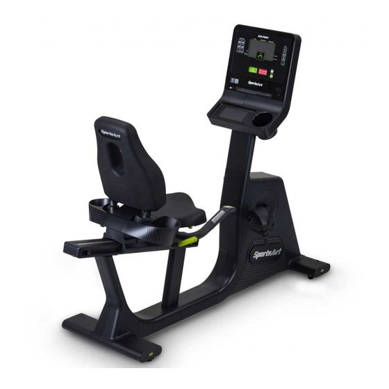
1. INTRODUCTION Congratulations on the purchase of a high quality SportsArt product, the C574R -13” recumbent exercise cycle. Constructed of high quality materials and designed for years of reliable performance, this product was made for full commercial use. Before this product is assembled or operated, we recommend that you familiarize yourself with this manual. -
Page 6: Safety Precautions
2. SAFETY PRECAUTIONS This product was designed and built for optimum safety. However certain precautions apply during the use of this product. Please note the following safety precautions: ● To reduce the risk of personal injury, read and understand all the instructions before using this product. - Page 7 2. SAFETY PRECAUTIONS (CONT.) ● Do not use accessories or parts that are not specifically recommended by the manufacturer (SportsArt). Such parts might cause injuries or cause the unit to fail and void the warranty. We will not be responsible for any safety issue that arises due to the misuse of accessories or parts.
- Page 8 2. SAFETY PRECAUTIONS (CONT.) ● This product must be grounded. If it should malfunction or breakdown, Improper grounding can increase the risk of electric shock. The product is equipped with a power cord having an equipment-grounding conductor and a grounding plug. The plug must be inserted into an appropriate outlet that is properly installed and grounded in accordance with all local codes and ordinances.
- Page 9 2. SAFETY PRECAUTIONS (CONT.) MARKINGS CAUTION: ● Read instruction manual before using. ● Do not let children on or near the product. WARNING: ● Heart rate monitoring system may be inaccurate. ● Over exercise may result in serious injury or death. ●...
-
Page 10: Warning Label Position
3. WARNING LABEL POSITION If you are in a Non-English speaking country, you can attach the warning label to the console panel as shown, otherwise, you can also stick it on a place where is clear and obvious. (please use the French version label in French-Speaking areas in North America, and the label will not be included in the other regions.) Note: Depending on the model, the appearance of the console is different,... -
Page 11: List Of Parts
4. LIST OF PARTS Assembly Parts Name Qty. No. Name Qty. A1 Main frame Left side bottle rack A2 Console Mast Right side bottle rack A3 Grip A10 Seat strut cover A4 Console A11 Power cord A5 Saddle A12 TV Terminal A13 Right pedal A6 Seat Back A14 Left pedal... - Page 12 4. LIST OF PARTS (CONTINUED) Hardware Kit Name Qty. Specification Notes Double open-end wrench 12mm*15mm Double open-end wrench 13mm*15mm*20 L-shaped Allen wrench M6*L70 L-shaped Allen wrench M5*L60mm L-shaped Allen wrench M5*L65mm Screwdriver Two Way Screwdriver + black bit (Philips/flat/ shank round) Round screw cap Philips screw...
-
Page 13: Assemble The Product
5. ASSEMBLE THE PRODUCT STEP 1 Install the Seat and Pedal Use the tool enclosed with the product to secure the left/right pedals (A13/A14) to the crank on the main frame, please note that pedal spindle threads are different from left side and right side. DO NOT install in reverse. -
Page 14: Step 2 Install The Handlebar/Saddle/Grip
STEP 2 Install the Handlebar/Saddle/Grip (a) Secure the handlebar(A7) with the screws (22), pull the cables out of the opening as shown and connect to the cables on the mainframe(A1). (b) Secure the saddle(A5) to the mainframe(A1) with the screws (23). (c) Turn the grip(A3) onto the mainframe(A1) to fix. -
Page 15: Step 3 Install The Seat Back And Bottle Rack
STEP 3 Install the Seat back and Bottle rack (a) Secure the seat back(A6) with the screws (25). (b) Install the seat strut cover (A10) for both side as shown. (Please note that when assembling the cover, the lower bevel is on the inside and the higher bevel is on the outside of the seat strut.) (c) Secure the left/right side bottle rack(A8/A9) to the mainframe(A1) with the screws (27). -
Page 16: Step 4 Install The Console And Console Mast
STEP 4 Install the Console and Console Mast (a) Remove the maintenance cover (60), then place the console mast (A2) in position and secure it with the screws (24). (b) Lift up the anti-slip pad (51) on the console (A4), then remove the screws (28) (11) and the rack (52), and secure the console(A4) to the console mast(A2) with the pre-installed screws (26). -
Page 17: Step 5 Move The Bike In Place
STEP 5 Move the Bike in Place Lift the seat carriage, then tilt the bike for moving. -
Page 18: Step 6 Level The Bike
STEP 6 Level the Bike Please apply force to the end of the bike to check if the leveling knob is stable on the ground. If not, adjust the levelers as follows: (a) Loosen the leveling knob. (b) Rotate the leveling knob downward to the ground to make it steady. (c) Tighten the leveling knob. -
Page 19: Step 7 Install The Power Cord
STEP 7 Install the Power Cord (1) Remove the screw (29) from the base of the bike. (2) Insert the power cord plug into the connector on the product. (3) Plug the power cord (A11) into the outlet and secure the power cord plug into place with the removed screw (29). -
Page 20: Step 8 Tv And Network Function
STEP 8 TV and Network Function (a) NETWORK: Connect to the Ethernet with the external network signal. (b) AV PORT: To support external DVD PLAYER or other multimedia players using AV output signal. (c) To support MYE Wireless TV Audio_Channel Receiver, and the other equipment that conform to the CSAFE specification. -
Page 21: Step 9 Seat Back Adjustment
STEP 9 Seat Back Adjustment Move the grip (A3) left and right to adjust the inclination of the seat back. -
Page 22: Step 10 Seat Fore And Aft Adjustment
STEP 10 Seat Fore and Aft Adjustment Pull up the handle right below the seat to move the seat forward and backward until you find the right position. -
Page 23: Step 11 Essential Functions Guide
STEP 11 Essential Functions Guide RESISTANCE: Adjust the weight or force you need to place on the pedals to move them. -
Page 24: Step 12 Maintenance Circuit Breaker
STEP 12 MAINTENANCE Circuit Breaker (a) A circuit breaker is an automatically operated electrical switch designed to protect an electrical circuit from damage caused by overcurrent/ overload or short circuit. A spring located under the push button causes the button at area D to lift up and the breaker to trip as shown. (b) After the fault is repaired by qualified technicians, press the push button to reset circuit breaker to resume normal operation as shown. -
Page 25: Understand The Senza Console
6. UNDERSTAND THE SENZA CONSOLE DISPLAY Overview C574R Series 13” Senza Console is designed to help users obtain their fitness goals in a simple and convenient way. Before using the cycle, please familiarize yourself with the features on the display so you can fully utilize the cycle and all it has to offer. -
Page 26: Display Specifications
DISPLAY Specifications Parameter Spec. RESISTANCE 1-40 SPEED 0.0-99.9 MPH or 0.0-99.9 KPH TIME 0:00-600:00 min HEART RATE 35-220 bpm DISTANCE 0.00-9999 Mile/Km CALORIES 0-9999 Cal 5-150 steps/ min Calories /Hour 0-9999 Cal/Hour Mets 0-99.99 QUICK START, GOALS, FAT BURN, INTERVAL, PROGRAM SENZA JOURNEYS, PLATEAU, HEART RATE, FITNESS TEST... -
Page 27: Operate The Product
7. OPERATE THE PRODUCT OPERATION Safe Operating Area (a) Safety clearance required as shown below. Do not allow people to be near this area when operating. (b) Noise emission under load is higher than without load. 600mm (23.6") -
Page 28: Operation Proper Workout Position
OPERATION Proper Workout Position (a) A good riding posture is illustrated below. (b) Always follow the directions for use and safety instructions given by the manufacturer. Over exercise or improper workout position may result in serious injury (c) Hold onto the handlebar while getting off the bike from left/right side. (d) This product is intended to build your leg and cardiovascular strength. -
Page 29: Operation Safely Get On/Off
OPERATION Safely Get On/Off Getting on the bike: Always be cautious when getting on the bike. Wait to get on until the pedals have come to a complete stop. Getting off the bike: Always be cautious when getting off the bike. Always wait until the pedals have come to a complete stop before taking your feet off of the pedals and dismounting. -
Page 30: Operation Start Screen
OPERATION Start Screen Turn on the power or press the wake-up key to go to start screen. Description of start screen buttons: Name of button Function Date and Time Displays the current time and date Touch this button to access workout pro- SELECT gram selection SA WELL+... -
Page 31: Operation Go Mode
OPERATION GO mode Press <GO> key, then the screen will start counting down by showing 3,2,1,0,GO on the display. The product will start with the default setting of 35 years old, weight 75 kg (165 lbs) and the PROGRAM will start in quick start – time mode, with resistance level 1. -
Page 32: Operation Workout Selection
OPERATION Workout Selection 1. At start screen, touch the Select icon to access“SELECT WORKOUT”. Select workouts on the screen: By swiping with your fingers, you can move between the workout options on the screen. The workout options are as follows: QUICK START, GOALS, FAT BURN, INTERVAL, SENZA JOURNEYS, PLATEAU, HEART RATE and FITNESS TEST. - Page 33 OPERATION Workout Selection (Cont.) 2. Workout selection can choose your own workout programs, here are some details explained below. QUICK START A workout mode option based on time, distance and calories that allows user to start a workout immediately. GOALS Set your own time, distance, and calorie goal.
-
Page 34: Operation Workout Status
OPERATION Workout Status During the workout, you can select the “VIEW Dashboard” page below the screen to check the exercise status of your workout process. There are a total of 9 status windows for various information views, and you can modify the information display format in the status windows by touching the▼symbol below the status windows. - Page 35 OPERATION Workout Status (Continued) Drop down Menu items Symbol Default Other Options Calories/Min Calories/Hour Calories Mets Set Target Calories Average RPM Change Speed...
-
Page 36: Operation Select Entertainment
OPERATION Select Entertainment You can select the “Select Entertainment” page below the screen, and the available multimedia features will be displayed. The features include TV, Internet, SENZA Journeys, Bluetooth Audio, USB Audio, USB Video, IPTV and AVIN, ANYCast, Youtube, Netflix, HDMI(optional) etc.: the small central window will display the selected multimedia screen immediately. -
Page 37: Operation View Entertainment
OPERATION View Entertainment The display mode that maximizes the selected multimedia capabilities; in addition to the multimedia display, a sidebar workout information display is also included, so the user can check their current workout status instantly while using the multimedia features. Description of icons in the “View Entertainment”... -
Page 38: Operation Cool Down
OPERATION COOL DOWN When finishing your target program (time, distance, calories) or when pressing the key “CoolDown Workout”, display will pop up “GOING TO COOL DOWN”, then the machine will enter a two-minute cool down period and count down from 2:00 to 0:00. OPERATION Idle Mode When the cycle stops running with no other activity for 2 minutes, the machine... -
Page 39: Operation Sa Well
OPERATION SA WELL+ Tap SA WELL+ to enter SA WELL+ Login page. First time user must create an user account with SA WELL+ App. After signing up, user information will be saved into the account. Login to your SA Well+ account to track your workouts. This will also allow you to download a created custom workout to the machine. -
Page 40: About Heart Rate Detection
8. ABOUT HEART RATE DETECTION Heart rate detection functions are selected at the time of purchase. Not every product has every type of heart rate detection. The following explains factors that influence the performance of two of the most common types of heart rate detection devices. -
Page 41: Guidelines For Exercise
9. GUIDELINES FOR EXERCISE HOW HARD SHOULD I EXERCISE? Studies show that to benefit from aerobic exercise, people need to maintain a certain heart rate during their workouts. Your heart rate training zone depends on your age and fitness level. The darkened area in the chart to the right represents the recommended heart rate training zone for people of various ages. -
Page 42: Maintenance
10. MAINTENANCE This section covers maintenance topics, including instructions on replacing a fuse, along with the presentation of a maintenance schedule, maintenance task list, one-year maintenance log, and Wiring diagram. MAINTENANCE Safety Precautions ● Please follow standard safety precautions when servicing on this product. ●... -
Page 43: Maintenance Error Messages
MAINTENANCE Error Messages Error messages can appear on this console as a troubleshooting aid. Error messages appear in the following format: “ERROR _8_x” to represent the communication abnormality with the drive board. Error code explanations are as follows: ERROR_8_1_: Startup communication abnormality. Resume operation when communication is normal. -
Page 44: Maintenance Lubrication
MAINTENANCE Lubrication If the seat does not move fore and aft easily, please follow the indication as below to lubricate the seat carriage. Push the seat forward until it stops. Add a few drops of silicone lubricant to the rear end of the sliding track on both sides, then move the seat forward and backward to allow the lubricant completely fill the entire sliding track. -
Page 45: Accessories
11. ACCESSORIES ACCESSORIES Standard USB CHARGER 1. Provides up to 5V, 1.5A of power for charging 2. Let you update all required software drivers for the product. 3. When plug an USB flash drive that contains music or video files in MP3/ MP4 format, the media player will be activated and the playlist will be displayed. -
Page 46: Accessories Option
ACCESSORIES Option SA WELL+ Member System This is designed specially by SportsArt to assist the user in managing their workout history. There are three ways to get connected with the member site: 1. Using a smartphone, connect to the unit via Bluetooth/WIFI and use the SA WELL+ App. -
Page 47: Appendixes
12. APPENDIXES APPENDIXES Specifications Model C574R 13’’ L : 1725 mm (68”) Dimensions W : 660 mm (26”) H : 1404 mm (55.2”) Overall Weight 96.5 kg (213 lbs) Maximum User 205 kg (450 lbs) Weight 100 - 120 V , 60Hz , 0.7A (USA) Power Requirement 200 - 240 V , 50Hz , 0.35A (EUROPE) Circuit Breaker... -
Page 48: Appendixes Wiring Diagram
APPENDIXES Wiring Diagram SA WELL Option SA WELL+ Connection SA WELL Board Display Board USB Board Control Board WIFI Board TV Board USB Board Bluetooth Board NFC Board EUP Board Headphone Board Contact HTR plates HTR Board RESISTANCE (Left) RESISTANCE (Right) HTR Hub Board Drive Board AC Console power board... -
Page 49: Appendixes Exploded Diagrams
APPENDIXES Exploded Diagrams Note: We reserve the right to revise the following diagrams at any time without notice to notify any person of such revisions. Please visit our official website www.gosportsart.com for the latest version. -
Page 50: Appendixes Product Disassembly
APPENDIXES Product Disassembly Follow sequence of index numbers 1 through 4 assigned to the figure below to disassemble the product, and be sure to remove all the retaining screws before performing disassembly. - Page 51 Your Authorized Distributor...
Need help?
Do you have a question about the ECO-NATURAL Elite C574R-13 and is the answer not in the manual?
Questions and answers