
Related Manuals for Viper 330V


Summary of Contents for Viper 330V
- Page 1 M M o o d d e e l l 3 3 3 3 0 0 V V I I n n s s t t a a l l l l a a t t i i o o n n G G u u i i d d e e ©...
- Page 2 The Bitwriter (p/n 998T) ® requires chip version 2.0 or newer to program this unit. N N O O T T E E : : This product is intended for installation by a professional installer only! Any attempt to install this product by any person other than a trained professional may result in severe damage to a vehicle’s electrical system and components.
-
Page 3: Table Of Contents
contents what is included ....3 data port—Bitwriter ..22 ® control module ....3 four-pin optional sensor harness .23 RED wire . - Page 4 © 2005 directed electronics, inc.
-
Page 5: What Is Included
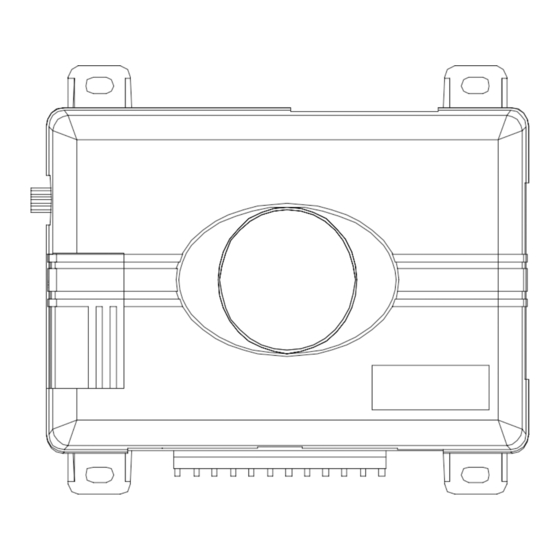
what is included Control module 4-pin sensor harness 12-pin main harness Valet switch 7-pin door monitor/Aux harness Siren 3-pin door lock harness Dual-diode light flash adapter Door lock pulse adapter control module DEALER OPTIONAL MASTER RECEIVER CONTROL (NOT USED) BITWRITER LOOP ®... -
Page 6: Before Beginning The Installation
Do not disconnect the battery if the vehicle has an anti-theft coded radio. If equipped with an airbag, avoid disconnecting the battery if possible. I I M M P P O O R R T T A A N N T T ! ! Please read this entire installation guide before beginning the installa- tion. -
Page 7: Deciding On Component Location
Solderless terminal crimpers Drill bit set Cordless power drill Phillips head screwdriver Torx driver set Work light deciding on component location control module Never put the control module in the engine compartment! The first step in hot-wiring a vehicle is removing the driver's side underdash panel to access the starter and ignition wires. -
Page 8: Valet/Program Switch
valet/program switch Ensure that the location you pick for the switch has sufficient clearance to the rear. The switch should be well hidden. It should be placed so passengers or stored items (such as in a glove box or center console) cannot accidentally hit it. -
Page 9: Connecting Your Wires
connecting your wires Now that you have decided where each component will be located, you’re going to find the wires in the car that the security system will be connected to. I I M M P P O O R R T T A A N N T T ! ! Do not use a 12V test light to find these wires! All testing described in this manual is described using a digital multimeter. -
Page 10: Finding A Parking Light Wire
1. Set to DCV or DC voltage (12V or 20V is fine). 2. Attach the (-) probe of the meter to chassis ground. 3. Probe the wire you suspect of being the ignition wire. The steering column harness or ignition switch harness is an excellent place to find this wire. -
Page 11: Finding The Door Pin Switch Circuit
changes more than a volt when using the dimmer, look for another wire. If it stays relatively close to (+)12V, you have found your parking light wire. (-) parking light wire Use the following procedure to find (-) parking light wire with your multimeter. Set to DCV or DC voltage (12V or 20V is fine). -
Page 12: Connection Guide
In most cars, fasten the (+) probe of your meter to (+)12V constant. Probe the wire you suspect of being the door trigger wire. If the meter reads (+)12V when any door is opened and the meter goes to 0 with the door closed, you have found a trigger wire. -
Page 13: Main Harness Wiring Guide
(-) 10A output. This is suitable for driving (-)parking light wires. N N O O T T E E : : A dual diode harness assembly is provided (Viper model only) for European vehicles which have parking light capability for illumination of only the parking lights on the side of the vehicle to the road when parked. - Page 14 LIGHT BULB WHITE H1/2 (+) 12V (-) LIGHT FLASH OUTPUT PARKING LIGHT RELAY OR SWITCH H H 1 1 / / 3 3 W W H H I I T T E E / / B B L L U U E E n n o o f f u u n n c c t t i i o o n n . . H H 1 1 / / 4 4 B B L L A A C C K K / / W W H H I I T T E E ( ( - - ) ) 2 2 0 0 0 0 m m A A d d o o m m e e l l i i g g h h t t - - s s u u p p e e r r v v i i s s i i o o n n o o u u t t p p u u t t : : Connect this wire to the optional domelight supervision relay.
- Page 15 H H 1 1 / / 5 5 G G R R E E E E N N ( ( - - ) ) d d o o o o r r t t r r i i g g g g e e r r i i n n p p u u t t : Most vehicles use negative door trigger circuits. Connect the green wire to a wire which shows ground when any door is opened.
- Page 16 H H 1 1 / / 8 8 B B L L A A C C K K ( ( - - ) ) c c h h a a s s s s i i s s g g r r o o u u n n d d c c o o n n n n e e c c t t i i o o n n : : Connect this wire to bare metal, preferably with a factory bolt rather than your own screw.
- Page 17 H H 1 1 / / 1 1 0 0 B B R R O O W W N N ( ( + + ) ) s s i i r r e e n n o o u u t t p p u u t t : : Connect this to the red wire of the siren. Connect the black wire of the siren to (-) chassis ground, preferably at the same point you con- nected the control module’s black ground wire.
-
Page 18: Auxiliary Harness Wire Connection Guide
auxiliary harness wire connection guide auxiliary harness wiring diagram BROWN (-) Horn Honk Output H2/1 GREEN Arm Input H2/2 Disarm Defeat Input H2/3 BLUE Disarm Input H2/4 GRAY (+) Trunk Release/Sensor Shunt Input H2/5 VIOLET/BLACK No Function H2/6 YELLOW/BLACK Light Flash Monitor Input H2/7 auxiliary harness wiring guide H H 2 2 / / 1 1 B B R R O O W W N N ( ( - - ) ) h h o o r r n n h h o o n n k k o o u u t t p p u u t t : : This wire supplies a 200 mA (-) output that can... - Page 19 vehicles operate this way. If this is the case connect the RED wire to the passenger unlock motor wire. When testing this wire be sure that it shows 12V (+) ONLY when the unlock button on the factory transmitter is pressed the second time to unlock the passenger doors.
-
Page 20: Keyless Entry Systems
BLUE wire then the alarm zones are bypassed (See Feature menu 1/8) and will remain bypassed until the ground input is removed. This means that when the trunk is open with the factory transmitter the only triggers that remain active while the trunk is open are the doors and ignition. - Page 21 external relays—driver’s door unlock This system is used in many four-door GM sedans. To test for this type of system, probe the unlock wire from the interior switch (black or white). Unlock the driver’s door, by itself, using the factory remote. If the switch wire shows (+) 12V, then use the follow- ing diagram: N N O O T T E E : : It is often easy to access the passenger unlock wire going to the rear door motor on the driver’s side.
- Page 22 no priority—driver’s door unlock This type of keyless entry system is common in import vehicles as well as many Jeep vehicles. When unlocking the doors with the transmitter all doors unlock at the same time. It is recommended to use H2/7 YELLOW/BLACK wire for Disarm Defeat instead of the H2/3 RED wire.
-
Page 23: Door Lock Harness Wire Connection Guide
door lock harness wire connection guide These door lock outputs are for Passive arming control of the factory door locks. They can also be used to control the door locks with the ignition switch for vehicle that do not have this feature in the factory RKE system. GREEN (-) Lock, (+) Unlock Output H3/A... -
Page 24: Valet/Program Button, 2-Pin
valet/program button, 2-pin BLUE plug The Valet/Program button should be accessible from the driver’s seat. It plugs into the BLUE port on the side of the unit. Since the system features Valet® by using the remote transmitter, the button can be well hidden. Consider how the button will be used before choosing a mounting location. -
Page 25: Four-Pin Optional Sensor Harness
four-pin optional sensor harness RED wire The red wire supplies constant power to the optional sensor. BLACK wire The black wire supplies ground to the optional sensor. BLUE, GREEN wires The blue and green wires are multiplex inputs. They are both tied to the same zone. If an input of less than 0.8 seconds is supplied to either wire the Warn-Away ®... -
Page 26: To Learn Lock
to learn lock: N N O O T T E E : : Make sure the doors, hood and trunk are closed so the factory RKE system oper- ates as it would when the user is using it. 1 1 . . W W i i t t h h a a l l l l t t h h e e d d o o o o r r s s , , h h o o o o d d a a n n d d t t r r u u n n k k c c l l o o s s e e d d : : Press and HOLD the Valet button. -
Page 27: To Exit The Learn Routine
N N O O T T E E : : If the Unlock learn was unsuccessful, the Unlock procedure can be repeated by using the LOCK learn procedure, except that at step 4 press and release the Valet ® button TWICE. (The LED will flash in groups of two flashes.) to exit the learn routine: Do one of the following: Turn the ignition on. -
Page 28: Internal Programming Jumper
internal programming jumper A 10A fuse is used as both a fuse and a program jumper. This jumper determines the light flash output polarity. In the (+) position, the on-board relay is enabled and the unit will output (+)12V on the WHITE wire, H1/2. In the (-) position, the on-board relay is enabled for (-) output on the WHITE wire, H1/2. -
Page 29: Long Term Event History
long term event history The control module will store the last 2 triggers in memory that are not erased when the ignition is turned on. This can be helpful for trouble shooting false alarm reports. To access the event history use the following procedure. 1. -
Page 30: Feature Programming
feature programming The feature programming routine is used to access and change any of the feature set- tings in the two menus below. The feature settings can be accessed and changed by using one of the following: The Valet button to enter the feature programming routine. ®... -
Page 31: Once A Feature Is Programmed
once a feature is programmed Another feature(s) can be programmed. The other feature menu can be selected. The Learn Routine can be exited. accessing another feature Release, then press and release the Valet button the number of times to advance ®... -
Page 32: Bitwriter Only Features
Bitwriter ® ONLY features Due to memory limitations for this system, the following features can only be pro- grammed using Directed’s Bitwriter programmer. Factory default settings are shown ® in b b o o l l d d . Forced passive arming ON Forced passive arming OFF NPC ON NPC OFF... -
Page 33: Features #1 Menu
features #1 menu Factory default settings are shown in b b o o l l d d . Feature Lock Button (one chirp) Unlock Button (two chirps) Step Active arming Passive arming Chirps ON Chirps OFF Door Trigger Error Chirp ON Door Trigger Error Chirp OFF Ignition-Controlled Domelight ON Ignition-Controlled Domelight OFF Panic Enabled (OEM upgrade) -
Page 34: Features #2 Menu
features #2 menu Factory default settings are shown in b b o o l l d d . N N O O T T E E : : Feature step number 6 and 7 are not applicable to the this model. Feature Lock Button (one chirp) Unlock Button (two chirps) -
Page 35: Features Description
features description bitwriter ® B-1 FORCED PASSIVE ARMING ON/OFF: These settings control whether the system arms passively in the event a door is left open accidentally by the user. Passive arming must be programmed on for this feature to work. •... -
Page 36: Menu #1
menu #1 1-1 ACTIVE/PASSIVE ARMING: These settings control the systems mode of arming. • Active arming mode (default): the system will only arm when the transmitter is used. • Passive arming mode: the system will arm automatically 30 seconds after the last door is closed or can be armed anytime using the transmitter. - Page 37 1-6 AUXILIARY/DELAYED ACCESSORY OUTPUT: These settings change Red/white auxiliary output operation. • Auxiliary output (default): in this setting if the system sees the vehicle doors lock 2 times rapidly the red/wht auxiliary channel will activate for 800mS. This is useful for adding trunk release option. •...
-
Page 38: Menu #2
1-11 HORN PULSE HONK DURATION: These settings adjust the pulse length of the optional horn honk output and allow for connection to more and less efficient vehicle horns without annoyingly loud arm/disarm honks. • 20mS (default): for more efficient vehicle horns •... - Page 39 2-4 DOOR LOCK PULSE DURATION: These settings control the pulse length of the door lock output. • 0.8seconds (Default): in this setting the output length is 800mS and can con- trol the majority of vehicle door lock systems. • 3.5 seconds: in this setting the output length is 3.5 seconds and is usually used in European vehicles with vacuum pump operated door locks.
-
Page 40: Troubleshooting
troubleshooting starter kill does not work: Is the correct starter wire being interrupted? If the car starts when the starter kill relay is completely disconnected, the wrong starter wire has been cut and interrupted. • Is the yellow wire connected to “true” ignition? Make sure this wire is connected to a wire that has power in the run and start positions. - Page 41 Door Lock Learn Routine does not learn door locks. • Check connections to be sure everything is properly connected. Refer to the Keyless Entry Systems—Three Types section of this guide for correct wire connections. Check the Door Lock Learn Routine section of this guide to ensure the correct pro- •...
- Page 42 © 2005 directed electronics, inc.
-
Page 43: Wiring Quick Reference Guide
wiring quick reference guide © 2005 directed electronics, inc.
Need help?
Do you have a question about the 330V and is the answer not in the manual?
Questions and answers