
Related Manuals for Charnwood W619


Summary of Contents for Charnwood W619
-
Page 1: Operating Instructions
8” TABLE SAW OPERATING INSTRUCTIONS MODEL: W619 Charnwood, Cedar Court, Walker Road, Bardon, Leicestershire, LE67 1TU Tel. 01530 516 926 Fax. 01530 516 929 email; sales@charnwood.net website; www.charnwood.net... -
Page 2: General Safety Rules
GENERAL SAFETY RULES WARNING: Do not attempt to operate the machine until you have read thoroughly and understood completely all instructions, rules, etc. contained in this manual. Failure to comply may result in accidents involving fire, electric shock, or serious personal injury. - Page 3 12.Wear proper apparel. Avoid loose clothing, gloves, ties, rings, bracelets, and jewellery which could get caught in moving parts. Non-slip footwear is recommended. Wear protective hair covering to contain long hair. 13.Always use safety glasses. Normal spectacles only have impact resistant lenses.
-
Page 4: Specification
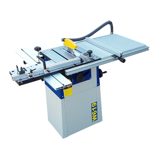
6.ALWAYS USE A PUSH STICK WHEN IT IS NECESSARY TO PUSH ANY PIECE OF MATERIAL OF SUCH SIZE THAT IT WOULD BRING YOUR HANDS WITHIN 30 CM OF THE BLADE. 7.Do not cut material that is badly warped or which has screws or nails in it 8.Be extra vigilant when cutting stock which has loose knots in it as these my fly out of the saw. - Page 5 Features Precision ground, cast iron table Precision ground cast iron sliding carriage Adjustable guide hells on sliding carriage to ensure accurate travel 0 to 45 blade tilt Quick stop for 90 position of crosscut fence Dust extraction for crown guard as well as body of saw Adjustable feet for easy levelling Tungsten carbide tipped blade Unpacking...
- Page 6 Assembly While the machine is on its side, take the four feet from the bag of parts and screw them into the four holes in the base. These feet can be adjusted by means of a spanner so that saw table is level after the machine has been put in place.
- Page 7 Loosen the nuts and lifting each bolt head in turn, slide one of the two longest aluminium extrusions over them The extrusion with the scale should be fitted to the front of the table, scale uppermost and in both cases the wide groove should face outwards. If they are difficult to slide on, make sure that you have slackened the nuts sufficiently and rock the extrusions gently as you move them along.
- Page 8 Now take the first of the extension tables, loosen the nuts and bolts and slide it onto the guide rails. Follow it with the second one and tighten all the locking nuts and bolts. If the tables do not slide into place easily, check that the front and back guide rails are really parallel and adjust the rear one if necessary.
- Page 9 With the plastic end to the right, slide the two clamping block onto the crosscut/mitre fence. The Work clamp passes though its block and locates in the large hole at the front of the carriage. The block with the Kipp handle has its tee headed bolt slid into the keyway on the carriage.
-
Page 10: Blade Removal And Replacement
Small cross cut and mitre fence. This may be used on either side of the blade. Adjustments to tilt and depth of cut should be made only when the saw is not running. Never force timber through the saw, always let it cut at its own speed. Always switch off and unplug the saw before removing or replacing the blade. - Page 11 PARTS DIAGRAM A...
- Page 12 Circlip Rail support bracket Angle bracket...
- Page 13 Eccentric nut Hand grip Plastic moulding Threaded spindle...
- Page 14 Washer V belt Circlip Circlip Circlip Riving knife...
- Page 15 Rubber washer Washer...
- Page 16 Earth NVR switch...
Need help?
Do you have a question about the W619 and is the answer not in the manual?
Questions and answers