Charnwood W650 Owner's Manual
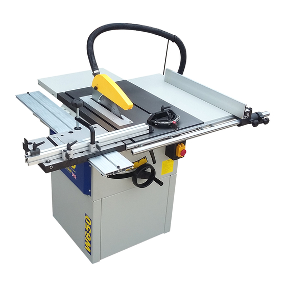
10” table saw
Hide thumbs
Also See for W650:
- Operating instructions manual (12 pages) ,
- Instructions (2 pages) ,
- Adjustment (3 pages)
Table of Contents
Advertisement
Quick Links
Advertisement
Table of Contents

Related Manuals for Charnwood W650


Summary of Contents for Charnwood W650
- Page 1 10” TABLE SAW OWNERS MANUAL MODEL: W650 Updated June 2018 Charnwood, Cedar Court, Walker Road, Hilltop Industrial Estate, Bardon Hill, Leicestershire, LE67 1TU Tel. 01530 516 926 Fax. 01530 516 929 email: sales@charnwood.net website: www.charnwood.net...
-
Page 2: General Safety Rules
GENERAL SAFETY RULES WARNING: Do not attempt to operate the machine until you have read thoroughly and understood completely all instructions, rules, etc. contained in this manual. Failure to comply may result in accidents involving fire, electric shock, or serious personal injury. Keep this owner's manual and review frequently for continuous safe operation. - Page 3 18. Always wear a face or dust mask if operation creates a lot of dust and/or chips. Always operate the tool in a well ventilated area and provide for proper dust removal. Use a suitable dust extractor. ADDITIONAL RULES FOR CIRCULAR SAWS 1.
-
Page 4: Specification
Specification Main table size 480(w) x 720(d) mm Rear table size 480(w) x 280 (d) mm Side Table size 270(w) x 720(d) mm Table height 830mm Motor (induction) 2200W (3hp), 240v single phase 254mm (10”) x 30mm Blade diameter and bore Blade rotation speed (no load) 4000 rpm Maximum depth of cut at 90... - Page 5 You will find these parts packed at the sides and inside the machine base. Using a cross-head screwdriver remove the blue cover to access the parts inside the base of the saw. Familiarise yourself with the parts Assembly Tilt the machine to one side and prop it up securely.
- Page 6 Using the long fence as a guide, level up the tables before tightening the bolts. Take the time to get this right as it is important to the accuracy of the saw. Take the rear extension table and remove these two bolts.
- Page 7 Prise out the plastic end cap from the guide rail extrusion. Feed the rail over the bolt heads, front bracket first, then on to the rear. Align the rear end of the rail with the rear edge of the cast table and re-tighten the four bolts.
- Page 8 The locking block has a T-shaped foot which slides in to the slot in the sliding carriage table. Fit the flip-over length stop by feeding the head of the bolt into the T-shaped slot on the top side of the fence. The ratchet handle locks the stop in place.
- Page 9 Place one hand wheel on the spindle protruding from the front of the saw. Rotate it so that the locking screw is in line with the flat on the spindle and tighten the screw. This wheel controls the rise and fall of the blade. Turn clockwise to raise the blade.
- Page 10 Connect one end of the extraction hose to the crown guard and the other end to the branch on the dust outlet using the hose clamps. Using the two screws and nuts provided, attach the hose hook through the two holes in the side of the extension table.
- Page 11 This double nut arrangement can be used to fine tune the alignment of the rip fence, so that it runs parallel to the blade. Slide the rip fence onto the guide rail. The fence can be locked into position with this locking knob.
-
Page 12: Changing The Blade
Changing the Blade Unplug the saw from the power source. Raise the blade height to its maximum and remove the crown guard. Undo the five screws securing the table insert and remove it. By hand, rotate the blade until the hole in the collar on the right hand side of the blade can be accessed. -
Page 13: Riving Knife Adjustment
Riving Knife Adjustment It is possible that the factory setting of the riving knife restricts the maximum cutting depth of the saw. If this is the case, the riving knife can be adjusted as follows: Ensure that the machine is isolated from the power supply. -
Page 14: Maintenance
Maintenance The following adjustments are all factory set when you buy a new saw. During the life of the machine it may be necessary to make some minor adjustments using the following guidance. Aligning The Blade To The Table Mitre T-Slot Disconnect the saw from the power supply and remove the blue panel from side of the saw base. - Page 15 Adjust the alignment of the sawblade to the table mitre T slot by moving the cast iron table over the base. Measure the distance between the blade and the table T slot at both the front and rear of the blade.
-
Page 16: Troubleshooting
When pressing start, nothing happens Check power supply, fuse in plug and switch. Declaration of Conformity for CE Marking Charnwood Declare that Woodworking Circular Saw, Model W650 Conforms with the following Directives: Machinery Directive 2006/42/EC Low Voltage Directive 2006/95/EC And further conforms to the machinery example for which the EC type examination Certificate No. - Page 17 CHARNWOOD W650 PARTS DIAGRAM A CHARNWOOD W650 PARTS LIST A Part No. Description Part No. Description A001 Underprop A002 Lower Leg A003 Hex Bolt M6 x 16mm A004 Washer M6 A005 Hex Nut M6 A006 Cover Board A010 Guide Rail...
- Page 18 A012 Washer M8 A013 Screw M8 x 10mm A016 Sliding Table Assembly. A017 Protective Cover A018 Hex Nut M6 A019 Washer M6 A020 Hex Bolt M6 x 16mm A021 Screw M6 x 10mm A022 Washer M6 A023 Large Washer M6 A024 Box Assembly A025...
- Page 19 CHARNWOOD W650 PARTS DIAGRAM B CHARNWOOD W650 PARTS LIST B Part No. Description Part No. Description ‘C’ Wire Ring B001 B002 Sliding Axle B003 Eccentric Bush B004 Thin Hex Nut M8 B005 Grub Screw M8 x 25mm B006 Eccentric Nut...
- Page 20 CHARNWOOD W650 PARTS DIAGRAM C CHARNWOOD W650 PARTS LIST C Part No. Description Part No. Description C001 Thread Nut C002 Thread Spindle C003 Bush Washer C004 Bush ‘C’ Ring 8mm C005 C006 Hex Locking Nut M6 C007 Large Washer M6...
- Page 21 C031 Large Washer M4 C032 Screw M4 x 12mm C033 Motor C034 Sliding Bolt C035 Large Washer M8 C036 Sliding Bush C037 Large Washer M8 C038 Hex Bolt M6 x 30mm C039 Spring Washer M6 C040 Large Washer M6 C041 Motor supporting Plate C042 Large Washer M8...
Need help?
Do you have a question about the W650 and is the answer not in the manual?
Questions and answers