Table of Contents

Related Manuals for Charnwood W625


Summary of Contents for Charnwood W625
- Page 1 TABLE SAW OPERATORS MANUAL MODEL: W625 Charnwood, Cedar Court, Walker Road, Hilltop Industrial Estate, Bardon Hill, Leicestershire, LE67 1TU Tel. 01530 516 926 Fax. 01530 516 929 email: sales@charnwood.net website: www.charnwood.net...
-
Page 2: General Safety Rules
GENERAL SAFETY RULES WARNING: Do not attempt to operate the machine until you have read thoroughly and understood completely all instructions, rules, etc. contained in this manual. Failure to comply may result in accidents involving fire, electric shock, or serious personal injury. Keep this owner's manual and review frequently for continuous safe operation. - Page 3 16. Disconnect the machine from power source before servicing and when changing the blade. 17. Never leave the machine running unattended. Turn the power off. Do not leave the machine until it comes to a complete stop. 18. Do not use any power tools while under the effects of drugs, alcohol or medication. 19.
-
Page 4: Specification
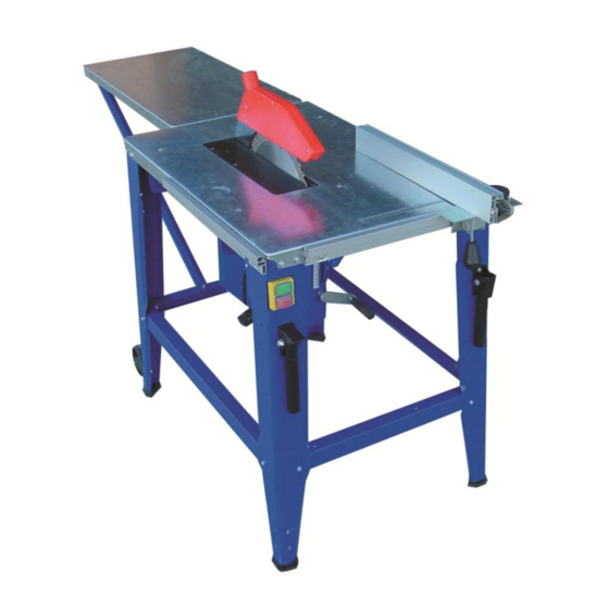
Specification Table size 550(w) x 1600(d)mm Table size with optional table extension 950(w) x 1600(d)mm Table height 800mm Motor (carbon brush) 1600W, 240v single phase 300mm (12”) 30mm Blade diameter and bore Blade rotation speed (no load) 3000 rpm Maximum depth of cut at 90 60mm Maximum depth of cut at 45 40mm... - Page 5 Unpacking This saw is best unpacked on the floor as it is quite heavy. Open the carton, carefully unpack all of the contents and lift the body of the saw onto a bench, leaving it inverted. Familiarise yourself with the parts and take the time to sort out the various types of nuts and bolts.
- Page 6 Bolt the four rails together as shown, using three M6 x 16mm bolts with washers and nuts in each corner. It does not matter which pair, the long or the short are on top but please keep this symmetrical. Place the four black rubber feet on the legs. True up the assembly and tighten all the bolts.
- Page 7 Offer up the NVR switch and fix it in place with the two self tapping screws provided. Bolt on the dust extractor port noting that the side entry faces away from the motor. Use four M3 x10mm long bolts. Fit the wheels using four M6 x 16mm bolts with washers and nuts.
- Page 8 Fit one end of the dust collection hose to the spigot on the back of the crown guard, fit the other end to the side inlet of the dust extractor port and clip the middle into the support bracket you have just fitted. Bolt on the two lifting handles, using two M6 x 16mm bolts, washers and nuts for each one.
- Page 9 Rip fence Mitre fence Optional Side Extension Table If you have purchased the optional right hand extension table; Bolt the two support braces to the right hand side floor stand rail. This gives support to the table while you are attaching it.
- Page 10 Optional Sliding Carriage Note: If installed, remove the mitre fence guiderail which is bolted to the left hand side of the table. Unpack the components and familiarise yourself with them. Identify the front and rear guide rail carriers. Fit one to each end of the left hand side of the table, as shown.
- Page 11 Setting The Sliding Table Firstly set the height: These holes are slotted so that the carrier may be adjusted up or down to bring the sliding carriage to the correct height. Ideally it will be just proud of the table (0.5mm to 1mm) to allow the work piece to easily slide over the main table.
- Page 12 There is an adjustable, flip-over length stop on the fence, to speed up repetitive work. Use a set square to set the mitre fence extrusion at 90 degrees to the blade. The mitre scale has two fixing screws which can be loosened to make an adjustment to the scale if necessary.
-
Page 13: Blade Removal And Replacement
Cutting Depth Adjustments to the cutting depth should be made only when the saw is not running. Turn the crank handle to set the blade to the required depth. Turn anticlockwise to lower the blade, turn clockwise to raise the blade. The blade height should always be set so that only the carbide tips of the blade (approx. -
Page 14: Troubleshooting
When pressing start, nothing happens Check power supply, fuse in plug and switch. Declaration of Conformity for CE Marking Charnwood Declare that Woodworking Circular Saw, Model W625 Conforms with the following Directives: Machinery Directive 2006/42/EC Low Voltage Directive 2006/95/EC... - Page 15 Charnwood W625 Exploded Diagram...
- Page 16 W625 Parts List Item Part Item Part Table Motor, Induction 240v, 1600w NVR switch Rail - long Depth of cut adjustment handle Rail - short Tilt locking knob Rear extension table Hinge Brace for extension table Pivot bolt (M6 x 8mm special)
- Page 17 Charnwood W625SC Exploded Diagram - Sliding Carriage Assembly W625SC Parts List Item Part Item Part Cap head bolt M6 x 16mm Cap head bolt Guide rail carrier – rear Self tapping screw End cap End cap Wing nut M6 Mitre fence extrusion...
Need help?
Do you have a question about the W625 and is the answer not in the manual?
Questions and answers