Advertisement
Quick Links
Advertisement

Related Manuals for Charnwood W629PSF


Summary of Contents for Charnwood W629PSF
- Page 1 10” TABLE SAW WITH PRECISION RIP FENCE OWNERS MANUAL MODEL: W629PSF Charnwood, Cedar Court, Walker Road, Hilltop Industrial Estate, Bardon Hill, Leicestershire, LE67 1TU Tel. 01530 516 926 Fax. 01530 516 929 email: sales@charnwood.net website: www.charnwood.net...
- Page 3 GENERAL SAFETY RULES WARNING: Do not attempt to operate the machine until you have read thoroughly and understood completely all instructions, rules, etc. contained in this manual. Failure to comply may result in accidents involving fire, electric shock, or serious personal injury. Keep this owner's manual and review frequently for continuous safe operation.
-
Page 4: Specification
8. Be extra vigilant when cutting stock which has loose knots in it as these my fly out of the saw. 9. NEVER remove the table insert when the saw is running. 10. To avoid exposure to hazardous dust, do not use this saw without connecting it to a suitable dust extractor. - Page 5 Remove the plastic cover and the items packed loosely around the base. Use a cross head screwdriver to remove 4 screws, then remove the blue side panel which has the tilt arbor shaft protruding through it. Remove items packed inside The machine is fixed to the base with two bolts.
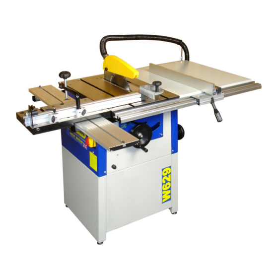
- Page 6 Identify the Loose Parts Fence Carrier Owner’s Manual Rear Table Cross Cut Extension Sliding Carriage Support Rail Fence Extrusion & Tools Tables Guide Rail Hose Clips Allen Keys Crown Guard Push Stick Tilt Handwheel Feet Rip Fence Dust Hose Rip Fence Bracket Mitre Fence Hose Support Rail Supports Hold Down Clamp Clamp/Fence Bracket Sliding Table with Rollers...
- Page 7 Assembly To assemble the base. Locate: 4 Panels 4 Feet 16 x M6 Bolt, Washer and nut Screw the 4 feet into the threaded holes in the 2 side panels of the base. Use a 17mm spanner to tighten them. After full assembly of the machine, the feet can be adjusted to level up the machine.
- Page 8 Invert the assembled base and mount it onto the upturned body of the machine. Use the remaining 4 x M6 bolt, washer and nut to attach the base to the saw body. Tighten with a 10mm spanner. Now tighten up the remaining 12 nuts and bolts of the base with a 10mm spanner.
- Page 9 There are two brackets at the rear of the saw. Each one has two hex headed bolts and nuts passing through it. Loosen the nuts and lifting each bolt head in turn, slide the 100cm long square aluminium extrusion over them. The rear table support extrusion should be fitted to the rear with the open side facing outwards.
- Page 10 Slide the front rail over the three bolt heads and hand tighten the nuts ensuring that the rail can still slide. Identify the Rip Fence Carrier and the Fence Extrusion. Undo the 2 wing nuts on the fence carrier until the fence extrusion can slide over the square head bolts as shown.
- Page 11 Set the rip fence onto the front rail so that the scale reads Zero. Press down the front handle to lock it in place. Slide the front rail, with the rip fence attached, so that the vertical face of the fence is touching the saw blade.
- Page 12 Add the second extension and, ensuring the tops of the tables are all level, re- tighten the eight bolts. Clip the saw guard to the riving knife and tighten the bolt sufficiently to hold it the set position while still allowing adjustment.
- Page 13 Fit the two support arms which will carry the guide rail for the sliding carriage. These are bolted to the left hand side of the table with four countersunk bolts Fit the wide guide rail extrusion by sliding it over the heads of the eight securing bolts.
- Page 14 The guide rail is fitted with front and rear travel stops. Move the rear travel stop to the back of the slot. Remove the front stop completely and fit the sliding carriage onto the guide rail so that the four bearing guides are located in the matching grooves along the sides of the rail.
-
Page 15: Riving Knife Adjustment
Check the Sliding carriage table is level to the main table. It should be level or slightly higher (up to 1mm) than the main table to allow a clamped work piece to move across the main table. If necessary, loosen and adjust the four silver support brackets to lift or level the sliding carriage. - Page 16 4) The two bolts holding the riving knife can now be loosened using a 13mm spanner 5) Raise the riving knife and crown guard assembly, so that the crown guard is situated just above the top of the saw blade. If necessary adjust the riving knife so that there is an even gap between the curved front of the knife and the radius of the blade.
- Page 17 Using the Table Saw Work Sliding Work Blade Mitre Stop Carriage Clamp Guard Fence Fence On/Off Blade Angle Blade Height Adjustable Blade Angle Switch Lock Adjuster Feet Adjuster On/Off Switch Slide the red section upwards and then lift the hinged cover. This will give you access to the green start and red stop buttons.
-
Page 18: Making A Cut
Blade Angle Adjustments to the angle of cut should be made only when the saw is not running. To tilt the blade for making bevel cuts, undo the blade angle lock, rotate the hand wheel to the required angle using the scale provided for guidance. Lock the angle by pressing down the locking lever. Making A Cut Ensure there is enough space around the table for the work piece before starting the cut. - Page 19 Cross Cutting With Sliding Carriage The sliding carriage is more suitable when working with large flat panels. To use the sliding carriage: Pull the table all the way forward. Set the flip over stop to the desired width of cut when required. If an angle is to be cut, undo the 2 thumb screws and ratchet lever, swing the fence to the desired angle and lock them both off...
-
Page 20: Maintenance
Blade Removal and Replacement Unplug the saw from the power source. Raise the blade to its maximum height and remove the saw guard from the riving knife. Remove the right hand table insert, using a 4mm Hex key to remove the two screws. Use the special spanner supplied, lock the spindle by fitting it over the black locking washer. - Page 21 4) Measure the distance between the blade and the T slot in the table at both the front and rear of the blade, ensuring that both measurements are the same. Also, ensure that the blade will clear the table and insert when fully tilted.
- Page 22 Using a suitable square, accurately adjust the blade to 90 degrees. Ensure that the square is positioned between teeth and is flat against the plate of the blade. Hold the limiting collar firmly against the Threaded Nut and retighten the grub screw. 45 Degree Stop Using a 4mm Allen Key, loosen the 45 degree limiting collar situated at the...
-
Page 23: Troubleshooting Guide
Troubleshooting Guide Problem Cause Remedy Machine does not start Blown Fuse Replace Fuse Loose switch terminal Inspect back of switch Faulty switch Replace switch Doors not closed (The machine is fitted with a safety interlock switch, it will not run if a door is open) Only starts when Green Faulty switch Replace switch... -
Page 24: Declaration Of Conformity
Declaration of Conformity Charnwood Declare that Woodworking Circular Saw Bench, Model W629 & W629PSF Conforms with the following EU Directives: Machinery Directive 2006/42/EC Low Voltage Directive 2006/95/EC Conforms with the following UK Regulations: Supply of Machinery (Safety) Regulations 2008 Electrical Equipment (Safety) Regulations 2016 And further conforms to the machinery example for which the type examination Certificate No. - Page 25 CHARNWOOD W629 PARTS DIAGRAM A...
- Page 26 CHARNWOOD W629 PARTS LIST A Foot Left / Right Base Panel Hex Nut M6 Washer M6 Base Panel Front Base Panel Rear Hex Bolt M6 x 16mm Hex Nut M5 Washer M5 Screw M5 x 12mm Dust Outlet 100mm diameter...
- Page 27 CHARNWOOD W629 PARTS DIAGRAM B CHARNWOOD W629 PARTS LIST B C Shaped Ring Sliding Axle Eccentric Bush Hex Thin Nut M8 Set Screw M8 x 25mm Eccentric Nut Trolley Washer M6 T-Shape Bolt Set Screw M8 x 10mm Eccentric Nut...
- Page 28 CHARNWOOD W629 PARTS DIAGRAM C CHARNWOOD W629 PARTS LIST C Screw M6 x 16 Dust Collector Hex Bolt M8 x 16mm Washer M8 Blade Locking Washer Saw Blade Driven Pulley Circlip M20 Bearing 6204 Circlip M47 Saw Axis Parallel Plate...
- Page 29 Bolt Shaft Hex Nut M8 Hand Wheel Washer M12 Hex Nut M12 SPAN Blade Lock Spanner Capacitor 20uf 450Vac M8 Stud CHARNWOOD W629 PARTS DIAGRAM E CHARNWOOD W629 PARTS LIST E T Shaped Runner Mitre Gauge Washer M8 Long Handle...
- Page 30 CHARNWOOD W629 PARTS DIAGRAM F CHARNWOOD W629 PARTS LIST F Scale – Self-Adhesive Fence Carrier Extrusion Hex Bolt M6 x 20mm Washer M6 Carrier End Cap – Left Nut M6 Carrier End Cap – Right Self-Tapping Screw Pip Fence Extrusion...
- Page 32 Updated October 2020 Charnwood, Cedar Court, Walker Road, Hilltop Industrial Estate, Bardon Hill, Leicestershire, LE67 1TU Tel. 01530 516 926 Fax. 01530 516 929 email: sales@charnwood.net website: www.charnwood.net...
Need help?
Do you have a question about the W629PSF and is the answer not in the manual?
Questions and answers