Table of Contents
Advertisement
Quick Links
Advertisement
Table of Contents

Related Manuals for Charnwood W618


Summary of Contents for Charnwood W618
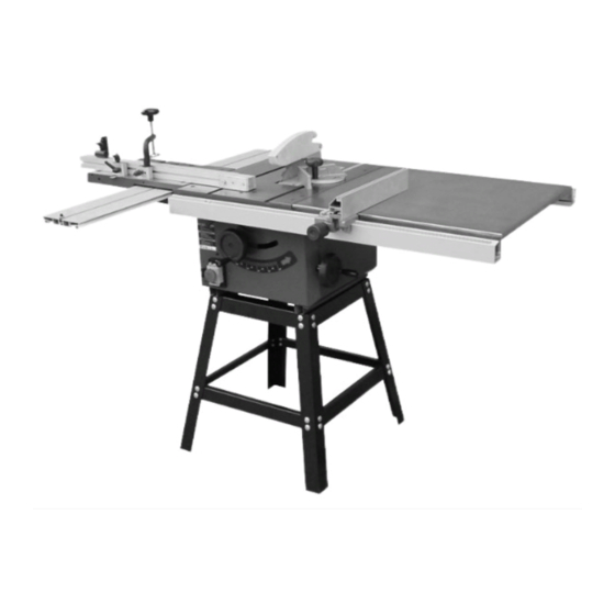
- Page 1 8” CAST IRON SAWBENCH WITH SLIDING CARRIAGE OPERATING INSTRUCTIONS MODEL: W618 Charnwood, Cedar Court, Walker Road, Bardon Hill, Leicestershire, LE67 1TU Tel. 01530 516926 Fax. 01530 516929 email; sales@charnwood.net website; www.charnwood.net...
-
Page 2: Technical Data
Introduction To get the most out of your new table saw, please read through this manual and safety instructions before use. Please also save the instructions in case you need to refer to them at a later date. Technical data Voltage/frequency 230 V ~ 50 Hz Motor (Induction) - Page 3 Safety Rules As with all machines, there is a certain amount of hazard involved with the use of this circular saw- bench. Use the machine with the respect and caution demanded where safety precautions are con- cerned. When normal safety precautions are overlooked or ignored, personal injury to the operator can result.
- Page 4 Large stock. Do not attempt to saw long or wide boards unsupported where spring or weight could cause the board to shift position. Job completion. If the operator leaves the machine area for any reason, he should turn “off” the power to the table saw motor and wait until the saw blade comes to a complete stop before his departure.
- Page 5 While working Wood must be hand fed uniformly and without jerking into the sawing tool, slightly more slowly when processing hard wood or work pieces, which produce large amounts of dust. Never move the work piece during a processing operation. Avoid uncomfortable working stances to reduce the risk of contacting the rotating sawing tool.
- Page 6 ASSEMBLY INSTRUCTIONS - Using M8 X 12mm coach bolts and M8 nuts bolt together two ‘A’ frames using two legs, one long strut in the middle and a short strut at the top (Fig.1 and Fig.2). Fig.1 Fig.2 - Join the two ‘A’ frames together using the remaining long bars in the middle and two short bars at the top (Fig.3).
- Page 7 - Attatch the two sliding carriage support arms to the Fig.6 underside of the cast iron saw table using 4 off M6 x 50mm countersunk bolts and 4 off M6 nut and washer (Fig.6) - Place an M6 x 16mm hexagen head bolt in each of the 4 clearance holes on the two support arms and loosely put an M6 nut and washer on the bottom of each (Fig.7)
- Page 8 Fig.13 - Fit an end stop in each end of the extruded carriage arm (Fig,13). - Slide the two connecting blocks into the T-slot on the angled fence making sure the clamp block is slid in first (Fig.14). Fig.14 - Slide the T-bolt of the left hand connecting block into the T-slot of the sliding carriage table (Fig.15).
- Page 9 - If the angle fence is not set at 90 degrees then undo the grub screw in the side of the sliding carriage table and using a flat screwdriver turn the eccentric bush until the angle is correct then tighten the grub screw (Fig21 & 22). Fig.21 Fig.22 - To set the angle fence to angles between...
- Page 10 - Place an M6 x 30mm domed pozi head screw and washer in the 3 holes in the front and rear of the main table. Attatch an M6 square nut to each. Slide the extruded support arms onto the nuts so that the nut sits in the T-slot (Fig.26, 27, 28, 29). Fig.26 Fig.28 Fig.27...
- Page 11 OPERATING INSTRUCTIONS Mounting and adjusting the Riving Knife Fig.35 Fig.34 Loosen the flange base with a 13 mm wrench and insert the riving knife. Adjust the riving knife and be sure to maintain a distance of approx. 3mm to the saw blade (Fig. 34). Securely fasten the riving knife with screw.
- Page 12 Adjusting the cutting height Adjust the height with the hand wheel (Fig. 41) Select a cutting height such that the saw blade teeth still protrude from the work piece to be cut. (Fig.42) Fig.42 Fig.41 Adjusting the Blade Angle Release the lock knob A (Fig.43). The saw blade can be tilted by up to 45º by rotating hand wheel B (Fig.43).
- Page 13 Fig.46 Fig.45 Sliding Mitre guide The mitre guide can be mounted on the left or right hand side of the saw blade in the T-groove. Diagonal cuts between 90ºand 45º can be exactly made.( Fig.47) Diagonal positioning is made possible by the 90ºorientation of the two supporting surface of the limit stop.
- Page 14 Malfunctions Machine vibrates Clamping levers for height and diagonal adjustment are not locked. Sawing tool is not tightly screwed. Cuts are not clean/wood is burned Sawblade is dull or incorrectly mounted. Rip fence is not parallel to the sawblade. Rapid sawing tool wear Sawing tool is incorrectly sharpened.
-
Page 15: Part List
Part List Part No Description Q’TY Part No Description Q’TY Set screw Shaft Washer Hand wheel Sawing base Sharp Setscrew Screw Plate Motor C-Spring Motor guidance plate Screw Arbor Screw Washer Handwheel Set screw Screw M20 Set screw Nut M20 Washer Threaded shaft Long plate... -
Page 16: Exploded View
EXPLODED VIEW... -
Page 18: Sliding Carriage
SLIDING CARRIAGE Part No Description Q’TY Part No Description Q’TY C-shaped ring Hex bolt M6X25 sliding axle Angle fence Eccentric bush “E” ring f16 Hex thin nut M8 Press handle Set screw M8X25 Square toes nut Eccentric nut Angle.ruler Trolley Sliding table Washer f6 Locking nut M10... - Page 19 Extension Table Floor Stand Sliding Carriage...
- Page 20 Charnwood, Cedar Court, Walker Road, Bardon Hill, Leicestershire, LE67 1TU Tel. 01530 516926 Fax. 01530 516929 email; sales@charnwood.net website; www.charnwood.net...
Need help?
Do you have a question about the W618 and is the answer not in the manual?
Questions and answers