Table of Contents

Related Manuals for Charnwood W629


Summary of Contents for Charnwood W629
- Page 1 10” TABLE SAW OPERATORS MANUAL MODEL: W629 Charnwood, Cedar Court, Walker Road, Hilltop Industrial Estate, Bardon Hill, Leicestershire, LE67 1TU Tel. 01530 516 926 Fax. 01530 516 929 email: sales@charnwood.net website: www.charnwood.net...
-
Page 2: General Safety Rules
GENERAL SAFETY RULES WARNING: Do not attempt to operate the machine until you have read thoroughly and understood completely all instructions, rules, etc. contained in this manual. Failure to comply may result in accidents involving fire, electric shock, or serious personal injury. Keep this owner's manual and review frequently for continuous safe operation. - Page 3 14. Disconnect the machine from power source before servicing and when changing the blade. 15. Never leave the machine running unattended. Turn the power off. Do not leave the machine until it comes to a complete stop. 16. Do not use any power tools while under the effects of drugs, alcohol or medication. 17.
- Page 4 Specification Table size 635 x420mm Table size with extensions 635 x 1000mm Motor (Induction) 2200W, 240v, 3hp Blade diameter x bore 250mm x 30mm Blade rotation speed (no load) 4000 rpm Maximum depth of cut at 90/45 degrees 70mm /45mm Cutting width with table extension 720mm Dust extractor hose connection...
- Page 5 Assembly While the machine is on its side, take the four feet from the bag of parts and screw them into the four holes in the base. These feet can be adjusted by means of a spanner to level the saw table after the machine has been put into place.
- Page 6 The extrusion with the measuring scale (Rip Fence Guide Rail) should be fitted to the front of the table, scale uppermost and in both cases the open side should face outwards. If they are difficult to slide on, make sure that you have slackened the nuts sufficiently and rock the extrusions gently as you move them along.
- Page 7 Slide the hose support clip onto the rear guide rail and lock it into place. Fit the dust collection hose to the saw guard and the spigot on the rear extraction point. Secure in place with the two hose clamps provided. Clip the hose into the support arm to hold it clear of the table.
- Page 8 Identify the crosscut fence. Place it with the open side, face down and the plastic tip to the right. Slide the pivot block and the locking block onto the back side of the fence with the head of the bolt in the T-slot. The Locking block has a T-shaped foot plate, slide it into the slot in the sliding carriage table.
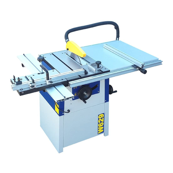
- Page 9 Using the Table Saw Rip Fence Mitre Fence Blade Angle Adjuster Blade Angle Lock Blade Height Adjuster Work clamp Sliding Carriage On/Off Switch Work Stop Adjustable Feet On/Off Switch Slide the red section upwards and then lift the hinged cover. This will give you access to the green start and red stop buttons.
- Page 10 Making a cut Ensure there is enough space around the table for the work piece before starting the cut. Position your feet in a stable and balanced stance. When feeding the timber, place your hands on the section of timber being kept. Never hold the waste part of the timber.
- Page 11 If an angle is to be cut, undo the thumb screw and ratchet lever, swing the fence to the desired angle and lock them both off. If necessary, undo both thumb screws and adjust the fence so that the plastic tip is just clear of the blade.
-
Page 12: Troubleshooting
Troubleshooting Problem Cause Remedy Machine does not start Blown Fuse Replace Fuse Loose switch terminal Inspect back of switch Faulty switch Replace switch Only starts when Green Faulty switch Replace switch button is held down Machine does not run but Failed capacitor Replace the motor start buzzing noise heard from... - Page 13 Declaration of Conformity for CE Marking Charnwood Declare that Circular Saw Bench, Model W629 Conforms with the following Directives: Machinery Directive 2006/42/EC Low Voltage Directive 2006/95/EC And further conforms to the machinery example for which the EC type examination Certificate No. BM 50259867 and AN 50259868 have been issued by TUV Rheinland LGA Products GmbH, Tillystrasse 2, 90431 Nurnberg, Germany.
- Page 14 CHARNWOOD W629 PARTS DIAGRAM A...
- Page 15 CHARNWOOD W629 PARTS LIST A Foot Left / Right Base Panel Hex Nut M6 Washer M6 Base Panel Front Base Panel Rear Hex Bolt M6 x 16mm Hex Nut M5 Washer M5 Screw M5 x 12mm Dust Outlet 100mm diameter...
- Page 16 CHARNWOOD W629 PARTS DIAGRAM B CHARNWOOD W629 PARTS LIST B C Shaped Ring Sliding Axle Eccentric Bush Hex Thin Nut M8 Set Screw M8 x 25mm Eccentric Nut Trolley Washer M6 T-Shape Bolt Set Screw M8 x 10mm Eccentric Nut...
- Page 17 CHARNWOOD W629 PARTS DIAGRAM C CHARNWOOD W629 PARTS LIST C Screw M6 x 16 Dust Collector Hex Bolt M8 x 16mm Washer M8 Blade Locking Washer Saw Blade Driven Pulley Circlip M20 Bearing 6204 Circlip M47 Saw Axis Parallel Plate...
- Page 18 Hand Wheel Washer M12 Hex Nut M12 SPAN Blade Lock Spanner Capacitor 20uf 450Vac M8 Stud CHARNWOOD W629 PARTS DIAGRAM D CHARNWOOD W629 PARTS LIST D Locking Handle Hex Bolt M6 x 25mm Washer M6 Fixing Plate Rip Fence Bracket...
- Page 19 CHARNWOOD W629 PARTS DIAGRAM E CHARNWOOD W629 PARTS LIST E T Shaped Runner Mitre Gauge Washer M8 Long Handle...
- Page 20 Charnwood, Cedar Court, Walker Road, Hilltop Industrial Estate, Bardon Hill, Leicestershire, LE67 1TU Tel. 01530 516 926 Fax. 01530 516 929 email: sales@charnwood.net website: www.charnwood.net...
Need help?
Do you have a question about the W629 and is the answer not in the manual?
Questions and answers