
Related Manuals for Intek TM-200S


Summary of Contents for Intek TM-200S
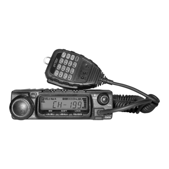
- Page 1 TM-200S PROFESSIONAL MOBILE TRANSCEIVER 136-175 MHz VHF FM 10W PC PROGRAMMABLE TM-400S PROFESSIONAL MOBILE TRANSCEIVER 400-490 MHz UHF FM 10W PC PROGRAMMABLE OWNER'S MANUAL...
- Page 2 Any modification to the product, alteration of the internal circuit, of the external structure of the radio or any programming in violation of the current regulations will automatically void the product certification and your right to use the product. INTEK S.R.L. declines any responsibility concerning any modification of the product, made by the user or by a third party, after delivery of the product.
-
Page 3: General Information
The use of VHF and UHF FM transceivers is subject to the regulations applied in the country where the product has to be used. As regulations are usually subject to possible modifications, please check the current regulations in your country with your dealer or local supplier. INTEK does not take any responsibility for illegal use and operation of this product not in accordance with the regulation of the country where the product is used. - Page 4 The use of VHF and UHF FM transceivers is subject to the regulations applied in the country where the product has to be used. As regulations are usually subject to possible modifications, please check the current regulations in your country with your dealer or local supplier. INTEK does not take any responsibility for illegal use and operation of this product not in accordance with the regulation of the country where the product is used.
-
Page 5: Table Of Contents
CONTENTS Shortcut Operations.............12 ..........1 Squelch Off/Squelch Off Momentary..........12 Supplied Accessories/Optional Accessories .....2 Squelch Level Setup ................ 12 Supplied Accessories............... 2 Channel Scan .................. 12 Optional Accessories ............... 2 CTCSS/DCS Encode and Decode Setup ........12 ..............3 CTCSS Scan..................13 Mobile Installation ................ - Page 6 Pilot Frequency ................22 1024 groups DCS Code..............28 PIN Setup ..................22 Declarations of Conformity ..........30 Address List ..................22 Declaration of Conformity TM-200S ..........30 Microphone Operation ............23 Declaration of Conformity TM-400S ..........30 Keypad Lock ................... 23 Notes ..................31 Transmitting DTMF by Microphone Keypad ........23...
-
Page 7: New And Innovative Features
New and Innovative Features INTEK Mobile Radios has nice housing, stoutness & stability, advanced and reliable functions, perfect & valuable. More functions as follows : Display on a large LCD with adjustable brightness, convenient for nighttime use. Distribute buttons reasonably, convenient for operation. Adopt superior quality material, better technology and high quality radiator to ensure stable and durable operation. -
Page 8: Supplied Accessories/Optional Accessories
Supplied Accessories/Optional Accessories Supplied Accessories After carefully unpacking the transceiver, identify the items listed in the table below. We suggest you keep the box and packaging. Transceiver Microphone Mobile Mounting DC Power Cable with Hardware Kit for Bracket Black screws Tapping screws (with DTMF keyboard) Bracket... -
Page 9: Mobile Installation
Initial Installation Determine the appropriate angle of the transceiver, using the 3 screw Mobile installation hole positions on the side of the mounting bracket. To install the transceiver, select a safe, convenient location inside your vehicle that minimizes danger to your passengers and yourself while the vehicle is in motion. -
Page 10: Dc Power Cable Connection
Initial Installation DC Power Cable Connection Locate the power input connector as close to the transceiver as possible. Mobile Operation The vehicle battery must have a nominal rating of 12V. Never connect the transceiver to a 24V battery. Be sure to use a 12V Black vehicle battery that has sufficient current capacity. - Page 11 Initial Installation Fixed Station Operation need a separate 13.8V DC power supply (not included), power supply ( SPA-8230) as optional accessories. Please contact local Regulated Power Supply dealer to require. (SPA-8230) The recommended current capacity of your power supply is 12A. Connect the DC power cable to the regulated DC power supply and ensure that the polarities are correct.
-
Page 12: Power Supply Voltage Display
Initial Installation Replacing Fuses If the fuse blows, determine the cause, then correct the problem. After the problem is resolved, replace the fuse. If newly installed fuses continue to blow, disconnect the power cable and contact your autho- rized dealer or an authorized service center for assistance. The range of displayed voltage is only from 7V to16V DC, because the displayed value is estimated, please use a voltmeter when a more precise reading is desired. -
Page 13: Accessories Connections
The wrong connecting way as the following picture. transceiver to your PC then using the optional programming cable (via Data socket ). Please use the free software for programming. Error www.intek-radios.com FSP-30 Ground Ask your dealer about purchasing the optional Programming Cable. -
Page 14: Front Panel
Getting Acquainted Front Panel Press key until key. NO. KEY FUN/SET V/M/MW Stores data into channels MHz/SHIFT NOT AVAILABLE ON THIS MODEL TS/DCS/LOCK Sets Keypad lock function Switches between HI, MID and LOW power CAL/ H/L transmission SQL/D Compander mode on/off Press NO. -
Page 15: Rear Panel
Getting Acquainted Rear Panel NO. KEY Squelch level. NOT AVAILABLE ON THIS MODEL NOT AVAILABLE ON THIS MODEL Decimal point NOT AVAILABLE ON THIS MODEL Decimal point NOT AVAILABLE ON THIS MODEL Indicates the channel number Signal is being received or monitor. NO. -
Page 16: Microphone
Getting Acquainted Microphone MIC Connector Diagram(in the front view of connector) NO. KEY Increase channel number or setting value. DOWN Decrease channel number or setting value. Press the PTT (Push-TO-Talk) key to transmit. Number Key Input DTMF dial out etc. D T M F O N / Switches between DTMF dialing or function operating. -
Page 17: Basic Operations
Basic Operations Switching the Power On/Off Receiving PWR KEY When the channel you are operating is called, the LCD display according to the option selected during shows and the signal intensity; in this way you can hear the installation Press the switch or turn the communication for transmitting party. -
Page 18: Shortcut Operations
Shortcut Operations Squelch OFF / Squelch OFF momentary Channel Scan key programmed as Squelch Off or Squelch Off Momentary to This function is designed to monitor signal in every channel. monitor the weak signal. Press key for 1s to enter into channel scan Squelch Off: Press key to disable squelch ,press again to resume squelch. -
Page 19: Ctcss Scan
Shortcut Operations When LCD appears iron, it means current channe can be set HIGH/MID/LOW Power Switch (*) with DCS encode and decode together, turn selector knob or press Press key until LCD display iron, Microphone's [ ] to select desired DCS encode and decode. -
Page 20: Keypad Lockout
Shortcut Operations Keypad Lockout Turn selector knob to choose group you Avoiding unintentional operation, this function will lock main keys, all desired. Total:16 group,01-16. keys except key are invalid. Press key to enter into editing of Press key until LCD displays current group,press MIC's numeric icon, then press key until, LCD... -
Page 21: General Setting
General Setting Turn selector knob to select the desired setup. The Setting of the radio can be modified only when the MENU function is enabled. In the default setting, the MENU function is disabled, it can "DTMFî : the channel will be mute by a DTMF signal. The be enabled by using the PC programming software. -
Page 22: Sending 2-Tone Call
General Setting Sending 2-Tone Call Content and name of 5TONE will be edited by programming Press and hold key for over 2s to enter general setting menu. software.This radio only query edited group or name.If there is corresponding name for 5TONE,this operation will display 5TONE P r e s s k e y t o c h o o s e corresponding name. -
Page 23: High/Mid/Low Power Selection
General Setting HIGH/MID/LOW Selection (*) If select "SQ",it indicates you can hear the calling from caller when receive a matching carrier. Press and hold key for over 2s to enter general setting menu. If LCD displays "CTC",it indicates you can hear the calling from caller Press key to choose No.07 when receive a matching carrier and... -
Page 24: Tx Off Setup
General Setting BU: Enable BCLO, Carrier lockout, transmitting is inhibited when TX OFF Setup current channel receives a matching carrier;press [PTT] to emit Disable this function,it is invalid to press PTT,current channel only error voice prompt and back to receiving status. works in RX mode. -
Page 25: Talk Around
General Setting Press key to choose No.14 Press key to choose No.12 menu, LCD displays "COMP--OFF". menu, LCD displays "REV--OF". Turn selector knob to select the desired Turn selector knob to select the desired setting. setting. ON:Enable compander ON:Enable Frequency Reverse OFF:Disable compander OFF:Disable Frequency Reverse. -
Page 26: Voice Prompt
General Setting Voice Prompt Press The prompting tone provides confirmation of entry, error status or malfunctions of the transceiver. You can enable or disable this function. Once APO is activated, the radio will be automatically switched off Press and hold key for over 2s to when the pre-set timer is running to end. -
Page 27: Squelch Level Setup
General Setting Scan Dwell Time Setup Squelch level Setup Setting the radio to a tight squelch level, you can avoid unwanted There are 3 kinds of Scan Dwell Time for option. signals or noise, but you may not receive a weak signal. Therefore, it will Press and hold key for over 2s to be better for you to select the normal squelch level... -
Page 28: Pilot Frequency
General Setting Pilot Frequency Address list You store desired ID and corresponding ID name in address list.The This function uses to start repeater .It needs a certain intensity Pilot LCD displays ID corresponding name if radio received ANI calling and Frequency to start dormant repeater.As usual,no need to send pilot frequency again once repeater started. -
Page 29: Microphone Operation
Microphone Operation DOWN Short Calling In standby,press to transmit the selected DTMF/2TONE/5TONE in current channel. Transmi tt ing DTMF Cod e:In standby,press ,LCD displays DTMF data and group.Press [ ] key to select the Numeric Keys desired transmitting DTMF group,then Press PTT to transmit. If no DTMF data in current group,LCD displays "EMPTY",press key again and input desired DTMF code by keypad,press PTT to DTMF ON/OFF... -
Page 30: Scan Skip
Microphone Operation Scan Skip In Channel mode,press then press ,decimal point displayed between frequency's ten digit and unit digit,it means current channel is This function can be temporarily used. When radio is turned off or scan skip. Repeat above operation to set scan or scan skip in current switched to another channel, the setting will back to default value. -
Page 31: Ctcss/Dcs Encode And Decode
Microphone Operation Voice Prompt CTCSS/DCS Encode and Decode The prompting tone provides confirmation of entry, error status or In standby,press ,then press to enter into CTCSS/DCS malfunctions of the transceiver. You can enable or disable this function. Encode and Decode. In standby,press ,then press ,LCD displays "BEEP--XXî. -
Page 32: Programming Software Installing And Starting (In Windows Xp System)
Install USB Cable Driver Program Click start menu in computer, under "ALL PROGRAMS" menu, choose and click "USB To Com port" on INTEK program, install "USB To Com port" driver by indication. Connect the optional USB Programming cable to USB port on PC anc connect the transceiver (see pic 1). -
Page 33: Specifications
70 dB (Wide) / 60 dB (Narrow) Intermodulation >65dB (Wide) / >60dB (Narrow) Audio output Transmitter RF output power 25W / 10W (VHF) (TM-200S) (*) 25W / 10W (UHF) (TM-400S) (*) Modulation Spurious & Harmonics in compliance with the R&TTE regulations ≤ 5 %... -
Page 34: Attached Chart
Attached Chart 50 groups CTCSS Tone Frequency (Hz) 1024 groups DCS Code 67.0 79.7 94.8 110.9 131.8 156.7 171.3 186.2 203.5 229.1 69.3 82.5 97.4 114.8 136.5 159.8 173.8 189.9 206.5 233.6 71.9 85.4 100.0 118.8 141.3 162.2 177.3 192.8 210.7 241.8 74.4 88.5 103.5 123.0 146.2 165.5 179.9 196.6 218.1 250.3 77.0 91.5 107.2 127.3 151.4 167.9 183.5 199.5 225.7 254.1... - Page 35 Attached Chart N is positive code, I is negative code, total: 232groups.
-
Page 36: Declarations Of Conformity
Declarations of Conformity Declaration of Conformity TM-200S Declaration of Conformity TM-400S EC Certificate of Conformity EC Certificate of Conformity (to EC Directive 2006/95, 2004/108, 99/5) (to EC Directive 2006/95, 2004/108, 99/5) DECLARATION OF CONFORMITY DECLARATION OF CONFORMITY With the present declaration, we certify that the following products :... -
Page 37: Notes
Notes... - Page 38 Notes...
- Page 39 Notes...
Need help?
Do you have a question about the TM-200S and is the answer not in the manual?
Questions and answers