
Related Manuals for DeLonghi DEF1407S


Summary of Contents for DeLonghi DEF1407S
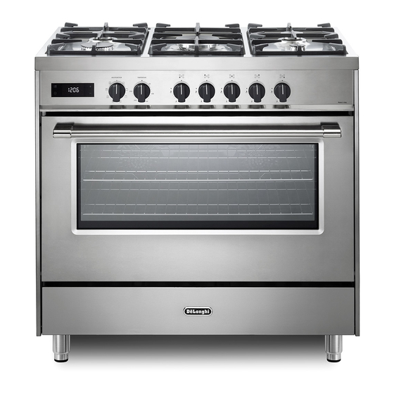
- Page 1 D E’ LO N G HI C OO KIN G INSTALLATION and SERVICE INSTRUCTIONS USE and CARE INSTRUCTIONS D EF1 407 S D UA L F U EL C OO K ER distributed by ELBA Appliances Australia (a Division of Fisher&Paykel Australia)
-
Page 2: Product Label
Dear Customer, Thank you for having purchased and given your preference to our product. The safety precautions and recommendations reported below are for your own safety and that of others. They will also provide a means by which to make full use of the features offered by your appliance. -
Page 3: Important Safety Precautions And Recommendations
IMPORTANT SAFETY PRECAUTIONS AND RECOMMENDATIONS IMPORTANT: This appliance is designed and manufactured solely for the cooking of domestic (household) food and is not suitable for any non domestic application and therefore should not be used in a commercial environment. The appliance guarantee will be void if the appliance is used within a non domestic environment i.e. - Page 4 ■ CAUTION: this appIiance must only be installed in a permanently ventilated room in compliance with the applicable regulations. ■ Do not operate your appliance by means of an external timer or separate remote-control system. ■ Do not carry out cleaning or maintenance operations on the appliance without having previously disconnected it from the electric power supply.
- Page 5 ■ WARNING: During use the appliance and its accessible parts become hot; they remain hot for some time after use. Care should be taken to avoid touching heating elements (on – the hob and inside the oven). The door is hot, use the handle. –...
- Page 6 Disconnect the appliance from the electrical power supply, let – the oven cool down and clean the interior of the oven with a cloth soaked in water and neutral detergent; then dry carefully. ■ CAUTION: Do not use harsh abrasive cleaners or sharp metal scrapers to clean the oven door glass since they can scratch the surface, which may result in shattering of the glass.
-
Page 7: Installation
INSTALLATION CAUTION: ■ This appliance must be installed according to AS/NZS 5601.1 (latest edition). ■ This appliance must be installed in accordance with these installation instructions. ■ This appliance shall only be serviced by authorized personnel. ■ This appliance is to be installed only by an authorised person in compliance with the current electrical regulations and in observation of the instructions supplied by the manufacturer. - Page 8 CLEARANCES Installation clearances and protection of combustible surfaces shall comply with the current local regulations eg. AS/NZS5601.1 (latest edition) Gas Installations code. Installation shall comply with the dimension in fig. 1a bearing in mind that. Overhead Clearances In no case shall the clearances between the highest part of the cooker be less than 650 mm or for an overhead exhaust fan 750 mm.
-
Page 9: Fitting The Adjustable Feet
GAS AND ELECTRIC CONNECTION Dotted line showing the position of the cooker when Figure 2 installed Area for gas connection 18.5 mm 18.5 mm Area for electrical connection (*) Depending on feet adjustment FITTING THE ADJUSTABLE FEET The adjustable feet must be fitted to the base of the cooker before use (figs. 3, 4). Rest the rear of the cooker on a piece of the polystyrene packaging exposing the base for the fitting of the feet. - Page 10 MOVING THE COOKER Figure 6a WARNING: When raising cooker to upright position always ensure two people carry out this manoeuvre to prevent damage to the adjustable feet (fig. 6a). WARNING - Be carefull: Do not lift the cooker by the door handle when raising to the upright position (fig.
-
Page 11: Anti-Tilt Bracket
ANTI-TILT BRACKET Figure 7 Important! To restrain the appliance and prevent it tipping accidentally, fit a bracket to its rear to fix it securely to the wall. Make sure you also fit the supplied lock pin to the anti-tilt bracket. If installing the cooker above a plinth (without fitting the adjustable feet), + 25... -
Page 12: Gas Supply
GAS SUPPLY ■ The connection must be performed by an authorised person according to the relevant standards. ■ Before connecting the appliance to the gas main, mount the brass conical adaptor onto the gas inlet pipe, upon which the gasket has been placed (figs. 10 - 11). Conical adaptor and gasket are supplied with the appliance (packed with conversion kit for use with Natural gas or ULPG). -
Page 13: Natural Gas
Gas connection for Gas connection for NATURAL GAS ULPG Gas inlet pipe Gas inlet pipe Nipple Nipple Gasket Gasket Brass conical adaptor Test Brass conical adaptor point (Thread tight: use (Thread tight: use suitable seal) suitable seal) Test point adaptor Gas regulator Test point... - Page 14 Adjust the test point pressure or supply pressure to the value which is appropriate for the gas type. The operation of the appliance must be tested when installation is completed. ■ Turn on the appliance gas controls and light each burner individually and in combination.
- Page 15 Auxiliary, Triple-ring Semi-rapid burner and Rapid burners Figure 14a Figure 14b MINIMUM BURNER SETTING ADJUSTMENT Check whether the flame spreads to all burner ports when the burner is lit with the gas tap set to the minimum position. If some ports do not light, increase the minimum gas rate setting.
- Page 16 TABLE FOR THE CHOICE OF THE INJECTORS Natural gas ULPG Test Point Pressure [kPa] 2.75 Injector Injector Orifice Dia. Orifice Dia. BURNER Consumption Consumption [mm] [MJ/h] [mm] [MJ/h] 0.92 3.90 3.90 Auxiliary (A) 0.56 Semi-rapid (SR) 1.17 6.50 0.70 6.30 0.98 Rapid (R) 1.54...
-
Page 17: Using The Oven For The First Time
USE AND CARE CAUTION: ■ This appliance must be used only for the task it has explicitly been designed for, that is for domestic cooking of foodstuffs. Any other form of usage is to be considered as inappropriate and therefore dangerous. ■... - Page 18 Figure 18 GREASE FILTERS (OPTIONAL COMPONENT, CAN BE PURCHASED SEPARATELY) ■ A special screen can be fitted at the back of the oven to catch grease particles, mainly when meat is being roasted. Slide in the grease filters on the back of the oven as in fig. 19 (one for each fan). ■...
- Page 19 TELESCOPIC SLIDING SHELF SUPPORTS The telescopic sliding shelf supports make it safer and easier to insert and remove the oven shelves and trays. They stop when they are pulled out to the maximum position. Important! When fitting the sliding shelf supports, make sure that you fit: ■...
-
Page 20: Control Panel
CONTROL PANEL Figure 21 Controls description Front right burner control knob Rear right burner control knob Central burner control knob Rear left burner control knob Front left burner control knob Oven temperature control knob Oven function selector control knob Electronic clock/programmer “Touch-controls” Oven temperature indicator 10. -
Page 21: Gas Burners
GAS HOB Figure 22 GAS BURNERS Natural Gas ULPG MJ/h MJ/h 3.90 3.90 1. Auxiliary burner (A) 2. Semi-rapid burner (SR) 6.50 6.30 3. Rapid (R) 11.75 11.75 3. Triple-ring burner (TR) 14.40 14.40 Notes: ■ The electric ignition is incorporated in the knobs. ■... - Page 22 GAS BURNERS (Auxiliary, Semi-rapid, Rapid and Triple ring) Gas flow to the burners is adjusted by turning the knobs (illustrated in fig. 24) which control the valves. Turning the knob, so that the indicator on itself points to the symbols printed on the control panel, achieves the following functions: AUXILIARY, Knob...
- Page 23 LIGHTING GAS BURNERS FITTED Figure 23 WITH FLAME FAILURE SAFETY DEVICE ELECTRONIC IGNITION (Auxiliary, Semi-rapid, Rapid and Triple ring) Check that the electricity is switched on to allow spark ignition. The gas flow to the burner is controlled by taps with safety cut-out device. If the burner flame should go out, the safety cut-off valve will automatically stop the gas flow.
- Page 24 CHOICE OF BURNER The burner must be chosen according to the diameter of the pans and energy required. For optimum efficiency uso a wok or pan no smaller than 230 mm diameter. Figure 25 do not use pans with concave or convex bases Burners Pan diameter Auxiliary...
- Page 25 (figs. 27, 28) CORRECT USE OF THE TRIPLE-RING BURNER ■ The flat-bottomed pans are to be placed directly onto the pan-support. ■ To use the WOK, you must place the wok stand in the CORRECT position as shown in figs. 27 - 28. IMPORTANT The special grille for wok pans (fig.
-
Page 26: Operating Principles
COOKING WITH MULTIFUNCTION OVEN OPERATING PRINCIPLES Attention: The oven door becomes Heating cooking very hot during operation. MULTIFUNCTION oven are obtained in the Keep children away. following ways: by normal convection GENERAL FEATURES The heat is produced by the upper and As its name indicates, this is an oven lower heating elements. -
Page 27: Thermostat Knob
Figure 29 Figure 30 (fig. 30) THERMOSTAT KNOB To turn on the heating elements of the oven, set the function selector knob on the desired program and the thermostat knob onto the desired temperature. To set the temperature, it is necessary to make the knob indicator meet the chosen number. The elements will turn On/Off automatically according to the energy need which is determined by the thermostat. -
Page 28: Defrosting Frozen Foods
GRILLING The infra-red heating element is switched on. The heat is diffused by radiation. Use with the oven door closed and the thermostat knob must be regulated between 50°C and 225°C maximum. Note: It is recommended that you do not grill for longer than 60 minutes at any one time. Attention: The oven door becomes very hot during operation. -
Page 29: Cooking Advice
SLOW HEATING AND KEEPING FOOD WARM The upper element and the circular element connected in series, are switched on; also the fan is on. The heat is diffused by forced convection with the most heat being produced by the upper element. The temperature must be regulated between 50°C and 140°C with the thermostat knob. -
Page 30: Use Of The Grill
possible, with a maximum difference OVEN COOKING of 20°C - 25°C. To cook, before introducing the food, preheat • The introduction of the different dishes the oven to the desired temperature. in the oven must be done at different When the oven has reached the desired times in relation to the cooking times temperature, introduce the food, control of each one. - Page 31 RECOMMENDED COOKING TEMPERATURE Shelf Cooking Food °C °F Mark Position* Time (approx) CAKES Victoria sandwich 2 or 3 20-25 mins Small cakes/buns 1 and 2 15-20 mins Maidera cake 2 or 3 20 mins Fruit cake hours Rich fruit cake 3 or 4 hours 8 - 9...
- Page 32 ELECTRONIC CLOCK “TOUCH-CONTROL” 10 9 8 7 6 Figure 31 2 3 4 Description of display symbols: Oven on Cooking time End of cooking time Timer Oven temperature AM/PM time format Screen brightness Acoustic signal volume Time of day setting 10.
-
Page 33: Setting The Clock
“TOUCH-CONTROL” KEYS The “touch-control” keys shall be operated by the fingers (just by touching the key). When using touch controls it is best to use the ball of your finger rather than the tip. Program and menu selection: after starting the procedure, the selection is automatically deactivated after approx. -
Page 34: Semi-Automatic Cooking
SEMI-AUTOMATIC COOKING This is used to automatically switch off the oven after the desired cooking time has elapsed. Check the clock shows the correct time. The semi-automatic cooking program can be set for a maximum period of 10 hours. Select the function and temperature (function and temperature knobs). The oven will come on. - Page 35 To cancel the automatic cooking program at any time, proceed as described in the “SEMI- AUTOMATIC COOKING” chapter. Turn the temperature and function knobs to the off position, otherwise continue cooking and then remember to turn the oven off manually. ATTENTION - VERY IMPORTANT (AUTOMATIC OR SEMI-AUTOMATIC COOKING): If a very short power interruption occurs, the oven keeps the programming.
-
Page 36: Screen Brightness Setting
SCREEN BRIGHTNESS SETTING It is possible to select three brightness levels. • Touch the " " key for more than 2 seconds, then touch the same key several times " symbol flashes. until the " • Touch the “+” or “―”; key; the display shows the brightness set (“d-01”, “d-02” or “d-03”). -
Page 37: Cleaning And Maintenance
CLEANING AND MAINTENANCE Maintenance Period Description ■ Daily Clean gas cooktop as per instructions below ■ Remove burner caps, burner rings & base and clean using non abrasive detergent & rinse in cold water & dry thoroughly before replacing back on hob Monthly ■... - Page 38 ENAMELLED PARTS All the enamelled parts must be cleaned with a sponge and soapy water or other non- abrasive products. Dry preferably with a microfibre or soft cloth. Acidic substances like lemon juice, tomato sauce, vinegar etc. can damage the enamel if left too long.
- Page 39 BURNERS ■ They can be removed. These parts must be cleaned using a sponge and soapy water or other suitable non-abrasive products. Dry with a soft cloth. Warning! Not dishwasher safe. ■ If left on the surface for a length of time, acidic substances such as lemon juice, tomato sauces and passata, vinegar and other similar products will damage the surface and dull its shine.
- Page 40 TRIPLE RING BURNER The triple ring burner must be correctly positioned (figs. 34 - 35); the burner rib must be located in position as shown by the arrow (fig. 34). The burner correctly positioned must not rotate (fig. 36). Then position the cap “A” and the ring “B” (figs. 35 - 36). Figure 34 Figure 35 Figure 36...
-
Page 41: Replacing The Oven Lights
REPLACING THE OVEN LIGHTS WARNING: Ensure the appliance is switched off before replacing the lamp to avoid the possibility of electric shock. WRONG ■ Let the oven cavity and the heating elements cool down. Figure 37 ■ Switch off the electrical supply. ■... -
Page 42: Removing The Oven Door
REMOVING THE OVEN DOOR Figure 39a The oven door can easily be removed as follows: ■ Open the door to the full extent (fig. 39a). ■ Open the lever “A” completely on the left and right hinges (fig. 39b). ■ Hold the door as shown in fig. - Page 43 REFIT THE DOOR Figure 40a Hold the door firmly (fig. 40a). Insert the hinge tongues into the slots, making sure that the groove drops into place as shown in the figure 40b. Open the door to its full extent. Fully close the levers “A” on the left and right hinges, as shown in the figure 40c.
-
Page 44: Service And Maintenance
SERVICE AND MAINTENANCE If the ignition spark fails to ignite or does not light the gas, check the following items before calling our Customer Service Centre to obtain the nearest Authorised Service Agent: ■ Burner is reassembled and located correctly. ■... -
Page 45: Electric Diagram
ELECTRIC DIAGRAM OKIDA Figure 41 (NO) ELECTRIC DIAGRAM KEY Oven fan motor Oven switch Oven bottom heating element Oven thermostat Ignition switches group TMS Safety thermostat Ignition coil Oven lamp Thermal overload (normally open) Cooling fan motor Terminal block Oven programmer Earth connection Oven top heating element Testing block... - Page 48 D esc ri pt i o n s an d i ll ustrations i n this book let are gi ven a s s im p ly i nd ica ti ve . T he m an u f ac t u re r re serves the right, considering th e ch a ra cter is tics o f the model s d es c ri be d he re, at any ti me and wi thout notice, to ma ke even tua l n ecess a ry modifi c at i o n s f o r t he i r construction or for co mm erci al n eed s.
Need help?
Do you have a question about the DEF1407S and is the answer not in the manual?
Questions and answers