
Related Manuals for Avalue Technology EAX-Q45


Summary of Contents for Avalue Technology EAX-Q45
- Page 1 EAX-Q45 Intel® Q45 LGA775 socket for Intel® Core™2 Quad ATX Motherboard User’s Manual Ver. 1.00...
-
Page 2: Table Of Contents
DV7560-Q45 Contents Safety information ......................4 About this guide ........................5 Typography ........................6 EAX-Q45 specifications summary..................7 1.1 Welcome!........................9 1.2 Package contents ......................10 1.3 Special features ......................11 1.3.1 Product highlights .....................11 1.4 Before you proceed ....................14 1.5 Motherboard overview....................15 1.5.1 Placement Direction....................15 1.5.2 Screw Holes......................15 1.5.3 Motherboard Layout....................16... - Page 3 2.2.1 Legend Box ......................44 2.2.2 List Box........................45 2.2.3 Sub-menu ......................45 2.3 Main Setup........................46 2.4 Advanced BIOS Setup ....................47 2.5 Advanced PCI/PnP Settings..................63 2.6 Boot Setting Configuration ..................67 2.7 Security Setup......................72 2.8 Chipset Setup......................73 2.9 Exit Menu........................78 EAX-Q45 User’s Manual 3...
-
Page 4: Safety Information
DV7560-Q45 Safety information Electrical safety To prevent electrical shock hazard, disconnect the power cable from the electrical outlet before relocating the system. When adding or removing devices to or from the system, ensure that the power cables for the devices are unplugged before the signal cables are connected. If possible, disconnect all power cables from the existing system before you add a device. -
Page 5: About This Guide
CAUTION: Information to prevent damage to the components when trying to complete a task. IMPORTANT: Instructions that you MUST follow to complete a task. NOTE: Tips and additional information to help you complete a task. EAX-Q45 User’s Manual 5... -
Page 6: Typography
DV7560-Q45 Typography Bold text Indicates a menu or an item to select Italics Used to emphasize a word or a phrase <Key> Keys enclosed in the less-than and greater-than sign means that you must press the enclosed key Example: <Enter> means that you must press the Enter or Return key <Key1>+<Key2>+<Key3>... -
Page 7: Eax-Q45 Specifications Summary
5V dual), 1 x COM header(RS-232/422/485), 1 x CPU Fan connector, 1 x Internal I/O Chassis Fan connector, 1 x System Fan connector, 1 x Front panel header, 1 x Chassis Intrusion header, 1 x 24-pin ATX Power connector, 1 x 4-pin ATX 12V EAX-Q45 User’s Manual 7... - Page 8 DV7560-Q45 Power connector Mechanical & Environment Power Type ATX mode Operating Temperature 0~60°C (32~140°F) Operating Humidity 0%~90% relative humidity, non-condensing 12" x 9.6" (304.8 mm x 243.84 mm) Size (L x W) * Specifications are subject to change without notice. 8 DV7560-Q45 User’s Manual...
- Page 9 User’s Manual This chapter describes the motherboard features and the new technologies it supports. Product Introduction EAX-Q45 User’s Manual 9...
-
Page 10: Welcome
DV7560-Q45 1.1 Welcome! Thank you for buying an ® EAX-Q45 motherboard! The motherboard delivers a host of new features and latest technologies, making it another standout in the long line of quality motherboards! Before you start installing the motherboard, and hardware devices on it, check the items in your package with the list below. -
Page 11: Special Features
With integrated dual display support, performance and support for Microsoft DirectX* 10, Shader Model 4.0 and OpenGL* 2.0, Intel GMA 4500 delivers excellent video and 3D graphics with outstanding graphics responsiveness. These enhancements deliver the performance and compatibility needed EAX-Q45 User’s Manual 11... - Page 12 DV7560-Q45 for today’s and tomorrow’s business applications. The Intel Q45 Express Chipsets include support for the latest PC operating systems, including Windows Vista*. Intel® Stable Image Platform Program Reducing the variety of supported hardware greatly simplifies enterprise and small medium business PC management, which is reflected in a lower total cost of ownership.
- Page 13 The CPU temperature is monitored by the ASIC (integrated in the Winbond Super I/O) to prevent overheating and damage. The system fan rotations per minute (RPM) is monitored for timely failure detection. The ASIC monitors the voltage levels to ensure stable supply of current for critical components. EAX-Q45 User’s Manual 13...
-
Page 14: Before You Proceed
DV7560-Q45 1.4 Before you proceed Take note of the following precautions before you install motherboard components or change any motherboard settings. Unplug the power cord from the wall socket before touching any component. Use a grounded wrist strap or touch a safely grounded object or a metal object, such as the power supply case, before handling components to avoid damaging them due to static electricity... -
Page 15: Motherboard Overview
The edge with external ports goes to the rear part of the chassis as indicated in the image below. 1.5.2 Screw Holes Place ten (10) screws into the holes indicated by circles to secure the motherboard to the chassis. Place this side towards the rear of the chassis EAX-Q45 User’s Manual 15... -
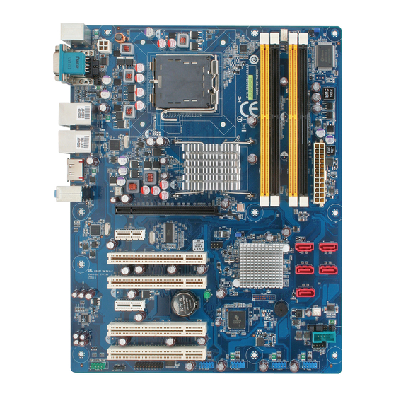
Page 16: Motherboard Layout
DV7560-Q45 1.5.3 Motherboard Layout 16 DV7560-Q45 User’s Manual... -
Page 17: Central Processing Unit (Cpu)
PnP cap. 1.6.1 Installing the CPU 1. Locate the CPU socket on the motherboard. Before installing the CPU, make sure that the socket box is facing towards you and the load lever is on your left. EAX-Q45 User’s Manual 17... - Page 18 DV7560-Q45 2. Press the load lever with your thumb (A), then move it to the left (B) until it is released from the retention tab. To prevent damage to the socket pins, do not remove the PnP cap unless you are installing a CPU. 3.
- Page 19 CPU! The motherboard supports Intel® LGA775 processors with the Intel® Enhanced Memory 64 Technology (EM64T), Enhanced Intel SpeedStep® Technology (EIST), and Hyper-Threading Technology. EAX-Q45 User’s Manual 19...
-
Page 20: Installing The Cpu Heatsink And Fan
DV7560-Q45 1.6.2 Installing the CPU Heatsink and Fan The Intel® Core™ 2 Quad/ Intel® Core™ 2 Duo LGA775 processor requires a specially designed heatsink and fan assembly to ensure optimum thermal condition and performance. Install the motherboard to the chassis before you install the CPU fan and heatsink assembly. - Page 21 Connect the CPU fan cable to the connector on the motherboard labeled CPU_FAN. Do not forget to connect the CPU fan connector! Hardware monitoring errors can occur if you fail to plug this connector. EAX-Q45 User’s Manual 21...
-
Page 22: Uninstalling The Cpu Heatsink And Fan
DV7560-Q45 1.6.3 Uninstalling the CPU Heatsink and Fan To uninstall the CPU heatsink and fan: 1. Disconnect the CPU fan cable from the connector on the motherboard. 2. Rotate each fastener counterclockwise. 3. Pull up two fasteners at a time in a diagonal sequence to disengage the heatsink and assembly... - Page 23 User’s Manual 5. Rotate each fastener clockwise to ensure correct orientation when reinstalling. The narrow end of the groove should point outward after resetting. (The photo shows the groove shaded for emphasis.) EAX-Q45 User’s Manual 23...
-
Page 24: System Memory
DV7560-Q45 1.7 System memory 1.7.1 Overview The motherboard comes with two 240-pin Double Data Rate 2 (DDR2) Dual Inline Memory Modules (DIMM) sockets. A DDR2 module has the same physical dimensions as a DDR DIMM but has a 240-pin footprint compared to the 184-pin DDR DIMM. DDR2 DIMMs are notched differently to prevent installation on a DDR DIMM socket. -
Page 25: Memory Configurations
Refer to the memory Qualified Vendors List on the next page for details. Due to CPU limitation, DIMM modules with 128 Mb memory chips or double-sided x16 memory chips are not supported in this motherboard. EAX-Q45 User’s Manual 25... -
Page 26: Installing A Dimm
DV7560-Q45 1.7.3 Installing a DIMM Make sure to unplug the power supply before adding or removing DIMMs or other system components. Failure to do so may cause severe damage to both the motherboard and the components. 1. Unlock a DIMM socket by pressing the retaining clips outward 2. -
Page 27: Removing A Dimm
DIMM. Support the DIMM lightly with your fingers when pressing the retaining clips. The DIMM might get damaged when it flips out with extra force. 2. Remove the DIMM from the socket. EAX-Q45 User’s Manual 27... -
Page 28: Expansion Slots
DV7560-Q45 1.8 Expansion slots In the future, you may need to install expansion cards. The following sub-sections describe the slots and the expansion cards that they support. Make sure to unplug the power cord before adding or removing expansion cards. Failure to do so may cause you physical injury and damage motherboard components. -
Page 29: Pci Slots
Express x1 network cards, SCSI cards and other cards that comply with the PCI Express specifications. The figure shows the type of network card that can be installed on the PCI Express x1 slot. EAX-Q45 User’s Manual 29... -
Page 30: Jumpers
DV7560-Q45 1.9 Jumpers 1.9.1 Clear RTC RAM (CLRTC) This jumper allows you to clear the Real Time Clock (RTC) RAM in CMOS. You can clear the CMOS memory of date, time, and system setup parameters by erasing the CMOS RTC RAM data. -
Page 31: Com1/2 Voltage Select (Jcompwr5, Jcompwr6)
User’s Manual 1.9.2 COM1/2 Voltage Select (JCOMPWR5, JCOMPWR6) This jumper allows you to select COM 1/2 Voltage power. 1.9.3 RS232/422/485 Select (JSETCOM1, JSETCOM2) This jumper allows you to select RS232/422/485. EAX-Q45 User’s Manual 31... -
Page 32: Intruder Select (Chassis1)
DV7560-Q45 1.9.4 Intruder Select (CHASSIS1) This jumper allows you to select Intruder. 32 DV7560-Q45 User’s Manual... -
Page 33: Connectors
USB 2.0 devices. 10. USB 2.0 ports 3 and 4. These two 4-pin Universal Serial Bus (USB) ports are available for connecting USB 2.0 devices. 11. VGA port. This 15-pin VGA port connects to a VGA monitor. EAX-Q45 User’s Manual 33... -
Page 34: Internal Connectors
DV7560-Q45 12. PS/2 keyboard port (purple). This port is for a PS/2 keyboard. 1.10.2 Internal connectors 1. Front panel audio connector (10-pin AAFP1) This connector is for a chassis-mounted front panel audio I/O module that supports either HD Audio or legacy AC’97 audio standard. It is recommended that you connect a high-definition front panel audio module to this connector to avail of the motherboard’s high‑definition audio capability. - Page 35 2. Serial Port connector (COM2) This connector is for a serial (COM) port. Connect the serial port module cable to this connector, then install the module to a slot opening at the back of the system chassis. EAX-Q45 User’s Manual 35...
- Page 36 DV7560-Q45 3. Fan Connectors (3-pin SYS_FAN, 3-pin, 4-pin CPU_FAN, CHA_FAN) The fan connectors support cooling fans of 350mA~740mA (8.88W max.) or a total of 1A~2.22A (26.64W max.) at +12V. Connect the fan cables to the fan connectors on the motherboard, making sure that the black wire of each cable matches the ground pin of the connector.
- Page 37 This connector is for USB 2.0 ports. Connect the optional USB module cable to any of these connectors, then install the module to a slot opening at the back of the system chassis. This USB connector comply with USB 2.0 specification that supports up to 480 Mbps connection speed. EAX-Q45 User’s Manual 37...
- Page 38 DV7560-Q45 5. ATX power connectors (20-pin EATXPWR, 4-pin ATX12V) These connectors are for ATX power supply plugs. The power supply plugs are designed to fit these connectors in only one orientation. Find the proper orientation and push down firmly until the connectors completely fit. Do not forget to connect the 4-pin ATX +12 V power plug;...
- Page 39 The system panel connector is color-coded for easy connection. Refer to the connector description below for details. Power/Soft-off button (Black 2-pin PWRSW) This connector is for the system power button. Pressing the power button turns the system EAX-Q45 User’s Manual 39...
- Page 40 DV7560-Q45 ON or puts the system in SLEEP or SOFT-OFF mode depending on the BIOS settings. Pressing the power switch for more than four seconds while the system is ON turns the system OFF. System Power LED connector (2-pin PWRLED) This 2-pin connector is for the system power LED.
- Page 41 It is a point-to-point interface standard, allows network equipment designers to develop an array of next-generation multi-service switches and routers to support multi-service traffic with aggregate bandwidths up to OC-192 (10 Gb/s) and beyond, enabling them to dramatically increase system performance. 10. Digital IO Connector (12-pin JDIO) EAX-Q45 User’s Manual 41...
-
Page 42: Bios Setup
DV7560-Q45 This chapter tells how to change the system settings through the BIOS Setup menus. Detailed descriptions of the BIOS parameters are also provided. BIOS Setup 42 DV7560-Q45 User’s Manual... -
Page 43: Managing And Updating Your Bios
Click Start, then select Run. d. From the Open field, type D:\bootdisk\makeboot a: assuming that D: is your optical drive. d. Press <Enter>, then follow screen instructions to continue. Copy the original or the latest motherboard BIOS file to the bootable floppy disk. EAX-Q45 User’s Manual 43... -
Page 44: Bios Setup Program
DV7560-Q45 2.2 BIOS setup program The main BIOS setup menu is the first screen that you can navigate. Each main BIOS setup menu option is described in this user’s guide. The Main BIOS setup menu screen has two main frames. The left frame displays all the options that can be configured. -
Page 45: List Box
Practice navigating through the various menus and submenus. While moving around through the Setup program, note that explanations appear in the Item Specific Help window located to the right of each menu. This window displays the help text for the currently highlighted field. EAX-Q45 User’s Manual 45... -
Page 46: Main Setup
DV7560-Q45 2.3 Main Setup When you first enter the Setup Utility, you will enter the Main setup screen. You can always return to the Main setup screen by selecting the Main tab. There are two Main Setup options. They are described in this section. The Main BIOS Setup screen is shown below. System Time/System Date Use this option to change the system time and date. -
Page 47: Advanced Bios Setup
Setup option by highlighting it using the <Arrow> keys. All Advanced BIOS Setup options are described in this section. The Advanced BIOS Setup screen is shown below. The sub menus are described on the following pages. EAX-Q45 User’s Manual 47... - Page 48 DV7560-Q45 2.4.1 CPU Configuration Setting You can use this screen to select options for the CPU Configuration Settings. Use the up and down <Arrow> keys to select an item. Use the <Plus> and <Minus> keys to change the value of the selected option. A description of the selected item appears on the right side of the screen.
- Page 49 User’s Manual Core Multi-Processing The item is to enable or disable the Core Multi-processing function. Intel® SpeedStep™ tech The choices of Execute-Disable Bit Capability are Enabled, Disabled. EAX-Q45 User’s Manual 49...
- Page 50 DV7560-Q45 2.4.2 IDE Configuration Setting You can use this screen to select options for the IDE Configuration Settings. Use the up and down <Arrow> keys to select an item. Use the <Plus> and <Minus> keys to change the value of the selected option. A description of the selected item appears on the right side of the screen.
- Page 51 35 is the default value. It is the recommended setting when all IDE connectors are set to AUTO in the AMIBIOS setting. Note: Different IDE disk drives take longer for the BIOS to locate than others do. EAX-Q45 User’s Manual 51...
- Page 52 DV7560-Q45 AHCI Configuration AHCI BIOS Support Enables for supporting AHCI BIOS. The choices are Enabled or Disabled. AHCI CD/DVD Boot Time Out Select the time out value for detecting AHCI CD/DVD device(s). 52 DV7560-Q45 User’s Manual...
- Page 53 When this option is set to Disabled, the serial port physically becomes unavailable. 3F8/IRQ4 Set this value to allow the serial port to use 3F8 as its I/O port address and IRQ4 for the interrupt address. This is the default setting. The majority of serial EAX-Q45 User’s Manual 53...
- Page 54 DV7560-Q45 port 1 or COM1 ports on computer systems use IRQ4 and I/O Port 3F8 as the standard setting. The most common serial device connected to this port is a mouse. If the system will not use a serial device, it is best to set this port to Disabled.
- Page 55 This shows the current System FAN operating speed. CHA_FAN Speed This shows the current Chassis FAN operating speed. Vcore/ 3VCC/ +12V/ +5V/ 5VSB/ 3VSB/ VBAT This shows the voltage of VCORE, 3VCC, +12V, +5V, 5VSB(V), 3VSB(V) and VBAT(V). EAX-Q45 User’s Manual 55...
- Page 56 DV7560-Q45 2.4.5 ACPI Configuration You can use this screen to select options for the ACPI settings. Use the up and down <Arrow> keys to select an item. Use the <Plus> and <Minus> keys to change the value of the selected option. The settings are described on the following pages. The screen is shown below.
- Page 57 User’s Manual Chipset ACPI Configuration This item allows you to set South Bridge ACPI Configuration. High Performance Event Timer This item allows you to enable or disable the High Performance Event Timer. EAX-Q45 User’s Manual 57...
- Page 58 DV7560-Q45 2.4.6 APM Configuration You can use this screen to select options for the APM settings. Use the up and down <Arrow> keys to select an item. Use the <Plus> and <Minus> keys to change the value of the selected option. The settings are described on the following pages. The screen is shown below.
- Page 59 <Arrow> keys to select an item. Use the <Plus> and <Minus> keys to change the value of the selected option. The settings are described on the following pages. The screen is shown below. DTAM Support The Choices are enabled or disabled the DTAM support. EAX-Q45 User’s Manual 59...
- Page 60 DV7560-Q45 2.4.8 Intel TXT (LT) Configuration You can use this screen to select options for the Intel TXT (LT) settings. Use the up and down <Arrow> keys to select an item. Use the <Plus> and <Minus> keys to change the value of the selected option.
- Page 61 <Arrow> keys to select an item. Use the <Plus> and <Minus> keys to change the value of the selected option. The settings are described on the following pages. The screen is shown below. Intel VT-d The Choices are enabled or disabled the Intel VT-d. EAX-Q45 User’s Manual 61...
- Page 62 DV7560-Q45 2.4.10 Trusted Computing You can use this screen to select options for the Intel Trusted Computing settings. Use the up and down <Arrow> keys to select an item. Use the <Plus> and <Minus> keys to change the value of the selected option. The settings are described on the following pages. The screen is shown below.
-
Page 63: Advanced Pci/Pnp Settings
Set this value to allow the system to modify the settings for Plug and Play operating system support. The default setting is No. Option Description The No setting is for operating systems that do not meet the Plug and Play EAX-Q45 User’s Manual 63... - Page 64 DV7560-Q45 specifications. It allows the BIOS to configure all the devices in the system. This is the default setting. The Yes setting allows the operating system to change the interrupt, I/O and DMA settings. Set this option if the system is running Plug and Play aware operating systems.
- Page 65 Use this setting only if there is an IDE adapter card installed in PCI Slot 6. This option is available even if the motherboard does not have a PCI Slot 6. If the motherboard does not have a PCI Slot 6, do not use this EAX-Q45 User’s Manual 65...
- Page 66 DV7560-Q45 setting. 2.5.8 IRQ Set this value to allow the IRQ settings to be modified. The default setting is available. Interrupt Option Description IRQ3 Available This setting allows the specified IRQ to be used by a PCI/PnP IRQ4 device. This is the default setting. IRQ5 IRQ7 IRQ9...
-
Page 67: Boot Setting Configuration
Select the Boot tab from the setup screen to enter the Boot Setup screen. You can display a Boot Setup option by highlighting it using the <Arrow> keys. All Boot BIOS Setup options are described in this section. The Boot BIOS Setup screen is shown below. EAX-Q45 User’s Manual 67... - Page 68 DV7560-Q45 2.6.1 Boot Settings Configuration You can use this screen to select options for the Boot settings. Use the up and down <Arrow> keys to select an item. Use the <Plus> and <Minus> keys to change the value of the selected option. The settings are described on the following pages. The screen is shown below.
- Page 69 Hit “DEL” Message Display Set this value to allow the Hit “DEL” to enter Setup Message Display to be modified. The default setting is Enabled. Option Description Disabled This prevents the to display Hit Del to Enter Setup EAX-Q45 User’s Manual 69...
- Page 70 DV7560-Q45 during memory initialization. If Quiet Boot is enabled, the Hit “DEL” message will not display. Enabled This allows the to display Hit Del to Enter Setup during memory initialization. This is the default setting. 2.6.2 Boot Device Priority Use this screen to specify the order in which the system checks for the device to boot from. To access this screen, select Boot Device Priority on the Boot Setup screen and press <Enter>.
- Page 71 Use this screen to view the hard disk drives in the system. To access this screen, select Hard disk drives on the Boot Setup screen and press <Enter>. The following screen displays examples of hard disk drives: 1st Drive This item specifies the boot sequence from the available device. EAX-Q45 User’s Manual 71...
-
Page 72: Security Setup
DV7560-Q45 2.7 Security Setup Select Security Setup from the Setup main BIOS setup menu. All Security Setup options, such as password protection and virus protection, are described in this section. To access the sub menu for the following items, select the item and press <Enter>: Change Supervisor Password The Security Setup screen is shown below. -
Page 73: Chipset Setup
You can display a Chipset BIOS Setup option by highlighting it using the <Arrow> keys. All Chipset BIOS Setup options are described in this section. The Chipset BIOS Setup screen is shown below. EAX-Q45 User’s Manual 73... - Page 74 DV7560-Q45 2.8.1 North Bridge Configuration You can use this screen to select options for the North Bridge Configuration. Use the up and down <Arrow> keys to select an item. Use the <Plus> and <Minus> keys to change the value of the selected option. Note: The North Bridge Configuration setup screen varies depending on the supported North Bridge chipset.
- Page 75 Disabled, Enabled 32MB, Enabled 64MB, and Enabled 128MB. PEG Port The choices are Auto or Disabled. Video Function Configuration DVMT Mode Select Use this field to select the memory to allocate for video memory. The choice is “DVMT”. EAX-Q45 User’s Manual 75...
- Page 76 DV7560-Q45 DVMT/Fixed Memory Size Specify the size of DVMT/system memory to allocate for video memory. 2.8.2 South Bridge Configuration You can use this screen to select options for the South Bridge Configuration. South Bridge is a chipset on the motherboard that controls the basic I/O functions, USB ports, audio functions, modem functions, IDE channels, and PCI slots.
- Page 77 Auto, Enabled, and Disabled. PCIE High Priority Port This setting allows to select the PCIE High Priority Port. The choices are Disabled, Port 0, Port 1, Port 2, Port 3, Port 4, and Port 5. EAX-Q45 User’s Manual 77...
-
Page 78: Exit Menu
DV7560-Q45 2.9 Exit Menu Select the Exit tab from the setup screen to enter the Exit BIOS Setup screen. You can display an Exit BIOS Setup option by highlighting it using the <Arrow> keys. All Exit BIOS Setup options are described in this section. The Exit BIOS Setup screen is shown below. 78 DV7560-Q45 User’s Manual... - Page 79 Setup and reboot the computer so the new system configuration parameters can take effect. Select Exit Saving Changes from the Exit menu and press <Enter>. Save Configuration Changes and Exit Now? [Ok] [Cancel] appears in the window. Select Ok to save changes and exit. EAX-Q45 User’s Manual 79...
- Page 80 DV7560-Q45 2.9.2 Discard Changes and Exit Select this option to quit Setup without making any permanent changes to the system configuration. Select Exit Discarding Changes from the Exit menu and press <Enter>. Discard Changes and Exit Setup Now? [Ok] [Cancel] appears in the window.
- Page 81 User’s Manual 2.9.3 Discard Changes Select Discard Changes from the Exit menu and press <Enter>. Discard Changes ? [Ok] [Cancel] appears in the window. Select Ok to discard changes. EAX-Q45 User’s Manual 81...
- Page 82 DV7560-Q45 2.9.4 Load Setup Default Automatically sets all Setup options to a complete set of default settings when you Select this option. The Optimal settings are designed for maximum system performance, but may not work best for all computer applications. In particular, do not use the Optimal Setup options if your computer is experiencing system configuration problems.
Need help?
Do you have a question about the EAX-Q45 and is the answer not in the manual?
Questions and answers