
Related Manuals for Avalue Technology EAX-R680FP


Summary of Contents for Avalue Technology EAX-R680FP
- Page 1 EAX-R680FP Intel® 12/13/14th Gen Core™ i9/i7/i5/i3 Processor ATX Motherboard with Intel® R680E Chipset User’s Manual Ed –04 March 2024 Part No. E2047FP6800R...
- Page 2 Disclaimer Avalue Technology Inc. reserves the right to make changes, without notice, to any product, including circuits and/or software described or contained in this manual in order to improve design and/or performance. Avalue Technology assumes no responsibility or liability for the...
- Page 3 Applications that are described in this manual are for illustration purposes only. Avalue Technology Inc. makes no representation or warranty that such application will be suitable for the specified use without further testing or modification.
- Page 4 A product returned without proof of the purchase date is not eligible for warranty service. Write the RMA number visibly on the outside of the package and ship it prepaid to your dealer. 4 EAX-R680FP User’s Manual...
-
Page 5: Table Of Contents
2.3.21 USB connector 1 (JUSB1) ......................31 2.3.22 USB connector (JUSB2) ........................ 31 2.3.23 USB connector 4 (JUSB4) ......................32 2.3.24 J1RS2 connector (J1RS2) ......................32 2.3.25 J1RS3 connector (J1RS3) ......................33 2.3.26 Auxiliary Fan connector (AUXFAN1) ..................... 33 EAX-R680FP User’s Manual... - Page 6 3.6.2.6.4 Serial Port 4 Configuration ....................53 3.6.2.6.5 Serial Port 5 Configuration ....................53 3.6.2.6.6 Serial Port 6 Configuration ....................54 3.6.2.7 CT6126D HW Monitor ......................54 3.6.2.7.1 Smart Fan Configuration ....................... 55 3.6.2.8 S5 RTC Wake Settings ......................56 6 EAX-R680FP User’s Manual...
- Page 7 3.6.6.3 Restore Defaults ........................79 3.6.6.4 Launch EFI Shell from filesystem device ................... 79 3.6.7 MEBx .............................. 79 4. Drivers Installation....................... 80 Install Chipset Driver ....................81 Install Graphics Driver ..................... 82 Install ME Driver ...................... 83 EAX-R680FP User’s Manual...
- Page 8 Install LAN Driver ....................86 Install RST Driver for RAID Mode ................88 Install Serial IO Driver ..................... 90 Install AscendingSortNetworkAdapterByMac ............91 5. Mechanical Drawing ....................92 Mechanical Drawing ....................93 Recommended Rubber Location................94 8 EAX-R680FP User’s Manual...
-
Page 9: Getting Started
1.2 Packing List Before you begin installing your single board, please make sure that the following materials have been shipped: 1 x EAX-R680FP Motherboard 2 x SATA Cables (for 2 x PCIex8 SKU, one additional SATA cable is ... -
Page 10: Document Amendment History
EAX-R680FP User’s Manual 1.3 Document Amendment History Revision Date Comment March 2024 Avalue Initial Release 10 EAX-R680FP User’s Manual... -
Page 11: Manual Objectives
User’s Manual 1.4 Manual Objectives This manual describes in details Avalue Technology EAX-R680RP Single Board. We have tried to include as much information as possible but we have not duplicated information that is provided in the standard IBM Technical References, unless it proved to be necessary to aid in the understanding of this board. -
Page 12: System Specifications
Onboard I/O COM1: by DB9 connector at rear IO support RS232 1 x 2 x 3 pin, pitch 2.00mm connector for COM1 pin9 RI/5V/12V, 0.9A jumper select (JRI1) COM2: by onboard pin-header support RS232/422/485 selected by BIOS 12 EAX-R680FP User’s Manual... - Page 13 1 x 2 x 5 pin, pitch 2.54mm pin-header for JME (JME1) Other 1 x 5 pin, pitch 2.54mm pin-header for +3.3S Level SMBus (JSMB1) 1 x 2 x 3pin, pitch 2.54mm pin-header for power f/w adjustment (JPC1) (not for user EAX-R680FP User’s Manual 13...
- Page 14 Power Mode AT / ATX mode Switchable Through Jumper No 10G LAN 0~55°C (32~131°F), 0.5m/s airflow Operating Temp. Dual 10G LAN 0~50°C (32~122°F), 0.5m/s airflow Storage Temp. -40~ +75°C Operating 40°C @ 95% Relative Humidity, Non-condensing 14 EAX-R680FP User’s Manual...
- Page 15 User’s Manual Humidity 12" x 9.6" (304.8mm x 243.84mm) Size (L x W) PCB material: NPG-170DZ Weight 1.54lbs (0.7kg) BIOS Support: OS Information Win11 64bit UEFI Linux Note: Specifications are subject to change without notice. EAX-R680FP User’s Manual 15...
-
Page 16: Architecture Overview-Block Diagram
EAX-R680FP User’s Manual 1.6 Architecture Overview—Block Diagram The following block diagram shows the architecture and main components of EAX-R680FP. 16 EAX-R680FP User’s Manual... -
Page 17: Hardware Configuration
User’s Manual 2. Hardware Configuration EAX-R680FP User’s Manual 17... -
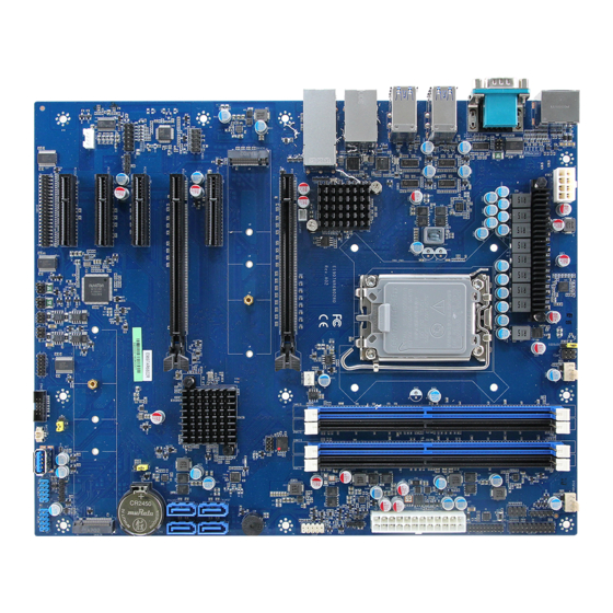
Page 18: Product Overview
EAX-R680FP User’s Manual 2.1 Product Overview 18 EAX-R680FP User’s Manual... -
Page 19: Jumper And Connector List
CPU fan connector 4 x 1 wafer, pitch 2.54mm CPUFAN1 System fan connector 1 SYSFAN1 4 x 1 wafer, pitch 2.54mm (with smart fan function supported) JFP1 Front Panel connector 5 x 2 header, pitch 2.54 mm EAX-R680FP User’s Manual 19... - Page 20 FAUD1 connector 5 x 2 header, pitch 2.54mm JESPI1 JESPI1 connector 6 x 2 header, pitch 2.00 mm REAR1 REAR1 connector 6 x 2 header, pitch 2.54mm 10GFAN1 10GFAN1 connector 2 x 1 wafer, pitch 2.00mm 20 EAX-R680FP User’s Manual...
-
Page 21: Setting Jumpers & Connectors
User’s Manual 2.3 Setting Jumpers & Connectors 2.3.1 Serial port 3 pin9 signal select (JRI3) Ring* +12V * Default 2.3.2 Serial port 2 pin9 signal select (JRI2) Ring* +12V * Default EAX-R680FP User’s Manual 21... -
Page 22: Serial Port 1 Pin9 Signal Select (Jri1)
EAX-R680FP User’s Manual 2.3.3 Serial port 1 pin9 signal select (JRI1) Ring* +12V * Default 2.3.4 BIOS ME function configuration (JME1) Enable ME * Disable ME * Default 22 EAX-R680FP User’s Manual... -
Page 23: Clear Cmos (Jcmos1)
CPU TDP (Watts) (JCFGID1) 2.3.6 **The original setting is not allowed to be changed by user** Config ID1 * Config ID0 * Default Note: Config ID0: JCFGID1(1-2) (For debug only) Config ID1: JCFGID1(2-3) For CPU Power FW setting (Default). EAX-R680FP User’s Manual 23... -
Page 24: At/Atx Power Mode Select (Jsatx1)
EAX-R680FP User’s Manual 2.3.7 AT/ATX Power Mode Select (JSATX1) ATX* * Default 2.3.8 General purpose I/O connector (DIO1) Signal PIN PIN Signal Au/6 5V_SMB_CLK 17 18 5V_SMB_DATA 24 EAX-R680FP User’s Manual... -
Page 25: Atx Power Connector (Atxpwr1)
User’s Manual 2.3.9 ATX Power connector (ATXPWR1) Signal PIN PIN Signal +V3P3S +V3P3S +V3P3S ATX_PSON# 16 ATX24_PWROK +V5A_SB +12V +12V +V3P3S 2.3.10 Power connector (ATX12V1) Signal PIN PIN Signal +V12S_CPU +V12S_CPU +V12S_CPU +V12S_CPU ATX_2X4_DET EAX-R680FP User’s Manual 25... -
Page 26: Smbus Connector (Jsmb1)
EAX-R680FP User’s Manual 2.3.11 SMBus connector (JSMB1) Signal SMB_CLK SMB_DATA SMB_ALERT# +V3P3S 2.3.12 Battery connector (BAT2) Signal +3.3V 26 EAX-R680FP User’s Manual... -
Page 27: Miscellaneous Setting Connector (Spi1)
User’s Manual 2.3.13 Miscellaneous setting connector (SPI1) Signal PIN PIN Signal + V3P3A_SPI SPI_CS0# SPI_CLK SPI_MISO SPI_MOSI SPI_HOLD# 2.3.14 Front Panel connector (JFP1) Signal PIN PIN Signal HDD_LED+ PWR_LED+ HDD_LED- PWR_LED- SYS_RST# PWRBTN# EAX-R680FP User’s Manual 27... -
Page 28: Cpu Fan Connector (Cpufan1)
EAX-R680FP User’s Manual 2.3.15 CPU fan connector (CPUFAN1) Signal +12V CPU_ FANIN CPU_FANOUT 2.3.16 System fan connector 1 (SYSFAN1) Signal +12V SYS_ FANIN SYS_FANOUT 28 EAX-R680FP User’s Manual... -
Page 29: External Speaker Connector (Jbz1)
User’s Manual 2.3.17 External Speaker connector (JBZ1) Signal 2.3.18 Auxiliary Panel connector (JAUXP1) Signal PIN PIN Signal SMB_CLK CASEOPEN# SMB_DATA ERROR_LED# FRONT_LAN1_ FRONT_LAN1_ACT 13 LINK100_1000# FRONT_LAN1_ LINK2500# FRONT_LAN2_ FRONT_LAN2_ACT 17 LINK100_1000# FRONT_LAN2_ LINK2500# EAX-R680FP User’s Manual 29... -
Page 30: Auxiliary Panel Connector (Jauxp2)
Auxiliary Panel connector (JAUXP2) Signal PIN PIN Signal FRONT_LAN3B_ACT FRONT_LAN3A_ACT FRONT_LAN3B_ FRONT_LAN3A_ LINK100_5G# LINK100_5G# FRONT_LAN3B_ FRONT_LAN3A_ LINK10G# LINK10G# 2.3.20 Serial port 2 connector (COM2) Signal PIN PIN Signal NRIB# NCTSB# NRTSB# NDSRB# NDTRB# NTXDB NRXDB NDCDB# 30 EAX-R680FP User’s Manual... -
Page 31: Usb Connector 1 (Jusb1)
User’s Manual 2.3.21 USB connector 1 (JUSB1) Signal Signal USB_14P USB_13P USB_14N USB_13N +V5A_USBD-E +V5A_USBD-E 2.3.22 USB connector (JUSB2) Signal USB_P6 USB_N6 +V5A_USB5-6 EAX-R680FP User’s Manual 31... -
Page 32: Usb Connector 4 (Jusb4)
EAX-R680FP User’s Manual 2.3.23 USB connector 4 (JUSB4) Signal Signal USB_12P USB_11P USB_12N USB_11N +5A_USBB-C +5A_USBB-C 2.3.24 J1RS2 connector (J1RS2) Signal PIN PIN Signal A422RX- A422RX+ A485TX+ A485TX- 32 EAX-R680FP User’s Manual... -
Page 33: J1Rs3 Connector (J1Rs3)
User’s Manual 2.3.25 J1RS3 connector (J1RS3) Signal PIN PIN Signal B422RX- B422RX+ B485TX+ B485TX- 2.3.26 Auxiliary Fan connector (AUXFAN1) Signal +12V AUX_R_FANIN EAX-R680FP User’s Manual 33... -
Page 34: Jpc1 Connector (Jpc1) **The Original Setting Is Not Allowed To Be Changed By User
EAX-R680FP User’s Manual 2.3.27 JPC1 connector (JPC1) **The original setting is not allowed to be changed by user** Signal PIN PIN Signal VCCCORE_nPMALERT VCCCORE_PMSDA VCCCORE_PMSCL +V3P3_EXT 2.3.28 Speaker connector (SPK1) Signal LSPK+ LSPK- RSPK+ RSPK- 34 EAX-R680FP User’s Manual... -
Page 35: S/Pdif Connector (Jspdif1)
User’s Manual 2.3.29 S/PDIF connector (JSPDIF1) Signal SPDIF_OUT 2.3.30 FAUD1 connector (FAUD1) Signal PIN PIN Signal MIC2_L MIC2_R +V3P3A LINE2_R MIC2_JD SENSE_B_JD3 LINE2_L LINE2_JD EAX-R680FP User’s Manual 35... -
Page 36: Jespi1 Connector (Jespi1)
2.3.31 JESPI1 connector (JESPI1) Signal PIN PIN Signal ESPI_ALERT# ESPI_RST# ESPI_CS1# ESPI_DEG_CLK ESPI_IO3 ESPI_CS# ESPI_IO2 PLT_RST#_BUF ESPI_IO1 +V3P3A ESPI_IO0 2.3.32 REAR1 connector (REAR1) Signal PIN PIN Signal MIC1_JD LINE1_JD AMP_DIS_JD MIC1_LIN MIC1_RIN LINE1_LIN LINE1_RIN FRONT_LIN FRONT_RIN 36 EAX-R680FP User’s Manual... -
Page 37: Serial Port Connector (4Com1)
NTXDC NDTRC# NDSRC# NRTSC# NCTSC# NRIC# NDCDD# NRXDD NTXDD NDTRD# NDSRD# NRTSD# NCTSD# NRID# NDCDE# NRXDE NTXDE NDTRE# NDSRE# NRTSE# NCTSE# NRIE# NDCDF# NRXDF NTXDF NDTRF# NDSRF# NRTSF# NCTSF# NRIF# 2.3.34 10GFAN1 connector (10GFAN1) Signal +12V EAX-R680FP User’s Manual 37... -
Page 38: Bios Setup
EAX-R680FP User’s Manual 3.BIOS Setup 38 EAX-R680FP User’s Manual... -
Page 39: Introduction
If you do not press the keys at the correct time and the system does not boot, an error message will be displayed and you will again be asked to. Press F1 to Continue, DEL to enter SETUP EAX-R680FP User’s Manual 39... -
Page 40: Using Setup
Note: Some of the navigation keys differ from one screen to another. To Display a Sub Menu Use the arrow keys to move the cursor to the sub menu you want. Then press <Enter>. A “” pointer marks all sub menus. 40 EAX-R680FP User’s Manual... -
Page 41: Getting Help
BIOS Vendor and your systems manufacturer to provide the absolute maximum performance and reliability. Even a seemingly small change to the chipset setup has the potential for causing you to use the override. EAX-R680FP User’s Manual 41... -
Page 42: Bios Setup
<Enter> to accept and enter the sub-menu. 3.6.1 Main Menu This section allows you to record some basic hardware configurations in your computer and set the system clock. 42 EAX-R680FP User’s Manual... -
Page 43: System Language
Visit the Avalue website (www.avalue.com.tw) to download the latest product and BIOS information. 3.6.2 Advanced Menu This section allows you to configure your CPU and other system devices for basic operation through the following sub-menus. EAX-R680FP User’s Manual 43... -
Page 44: Cpu Configuration
Number of E-cores to enable in each processor All[Default], package. Note: Number of Cores and E-cores are Active Efficient-cores 15/14/13/12/11/10/9/8 looked at together. When both are {0,0}, Pcode will /7/6/5/4/3/2/1/0 enable all cores. Disabled Hyper-Threading Enable or Disable Hyper-Threading Technology. Enabled[Default], 44 EAX-R680FP User’s Manual... -
Page 45: Efficient-Core Information
User’s Manual 3.6.2.1.1 Efficient-core Information 3.6.2.1.2 Performance-core Information EAX-R680FP User’s Manual 45... -
Page 46: Cpu - Power Management Control
P-states. Disabled Enable/Disable processor Turbo Mode (requires Turbo Mode Enabled[Default], EMTTM enabled too). AUTO means enabled. Disabled Enable/Disable CPU Power Management. Allows CPU C states Enabled[Default], to go to C states when it’s not 100% utilized. 46 EAX-R680FP User’s Manual... -
Page 47: Pch-Fw Configuration
MEBx Setup. Note: This Features Enabled[Default], option does not disable Manageability Features in FW. 3.6.2.3 AMT Configuration Item Description Unconfigure ME Unconfigure ME with resetting MEBx password to default on next boot. EAX-R680FP User’s Manual 47... -
Page 48: Firmware Update Configuration
Selects TPM device: PTT or dTPM. PTT - Enables PTT in TPM Device dTPM[Default], SkuMgr dTPM 1.2 - Disables PTT in SkuMgr Warning ! Selection PTT/dTPM will be disabled and all data saved on it will be lost. 48 EAX-R680FP User’s Manual... -
Page 49: Trusted Computing
3.6.2.4 Trusted Computing Item Options Description Enables or Disables BIOS support for security device. Security Device Disabled O.S. will not show Security Device. TCG EFI protocol Support Enabled[Default], and INT1A interface will not available. 3.6.2.5 ACPI Settings EAX-R680FP User’s Manual 49... -
Page 50: Super Io Configuration
Set Parameters of Serial Port 3 (COMC). Serial Port 4 Configuration Set Parameters of Serial Port 4 (COMD). Serial Port 5 Configuration Set Parameters of Serial Port 5 (COME). Serial Port 6 Configuration Set Parameters of Serial Port 6 (COMF). 50 EAX-R680FP User’s Manual... -
Page 51: Serial Port 1 Configuration
3.6.2.6.1 Serial Port 1 Configuration Item Option Description Disabled Serial Port Enable or Disable Serial Port (COM). Enabled[Default], 3.6.2.6.2 Serial Port 2 Configuration Item Option Description Disabled Serial Port Enable or Disable Serial Port (COM). Enabled[Default], EAX-R680FP User’s Manual 51... -
Page 52: Serial Port 3 Configuration
Set COM Port as RS232, RS422 or RS485 mode. RS485 3.6.2.6.3 Serial Port 3 Configuration Item Option Description Disabled Serial Port Enable or Disable Serial Port (COM). Enabled[Default], RS232[Default] UART 232 422 485 RS422 Set COM Port as RS232, RS422 or RS485 mode. RS485 52 EAX-R680FP User’s Manual... -
Page 53: Serial Port 4 Configuration
3.6.2.6.4 Serial Port 4 Configuration Item Option Description Disabled Serial Port Enable or Disable Serial Port (COM). Enabled[Default], 3.6.2.6.5 Serial Port 5 Configuration Item Option Description Disabled Serial Port Enable or Disable Serial Port (COM). Enabled[Default], EAX-R680FP User’s Manual 53... -
Page 54: Serial Port 6 Configuration
EAX-R680FP User’s Manual 3.6.2.6.6 Serial Port 6 Configuration Item Option Description Disabled Serial Port Enable or Disable Serial Port (COM). Enabled[Default], 3.6.2.7 CT6126D HW Monitor 54 EAX-R680FP User’s Manual... -
Page 55: Smart Fan Configuration
/Mode 08/Mode 09 Avalue Smart Fan Mode Select: Mode 01 to Mode 20 SYS FAN Mode /Mode 10/Mode 11 Or Manual (No Smart Fan) /Mode 12/Mode 13 /Mode 14/Mode 15 /Mode 16/Mode 17 /Mode 18/Mode 19 /Mode 20 EAX-R680FP User’s Manual 55... -
Page 56: S5 Rtc Wake Settings
Enable or disable System wake on alarm event. Select Disabled[Default], FixedTime, system will wake on the hr::min::sec Wake system from S5 Fixed Time specified. Select Dynamic Time, System will wake on Dynamic Time the current time + Increase minute(s). 3.6.2.9 Serial Port Console Redirection 56 EAX-R680FP User’s Manual... -
Page 57: Usb Configuration
Mass storage device emulation type. ‘AUTO’ Floppy enumerates devices according to their media format. Mass Storage Devices Forced FDD Optical drives are emulated as ‘CDROM’, drives with Hard Disk no media will be emulated according to a drive type. CD-ROM EAX-R680FP User’s Manual 57... -
Page 58: Network Stack Configuration
EAX-R680FP User’s Manual 3.6.2.11 Network Stack Configuration Item Options Description Disabled[Default], Network Stack Enable/Disable UEFI Network Stack. Enabled 3.6.2.12 NVMe Configuration 58 EAX-R680FP User’s Manual... -
Page 59: Chipset
User’s Manual 3.6.3 Chipset 3.6.3.1 System Agent (SA) Configuration Item Option Description Disabled VT-d VT-d capability Enabled[Default] EAX-R680FP User’s Manual 59... -
Page 60: Memory Configuration
EAX-R680FP User’s Manual 3.6.3.1.1 Memory Configuration 3.6.3.1.2 Graphics Configuration Item Option Description Auto[Default] Select which of IGFX/PEG Graphics device should be Primary Display IGFX Primary Display. PEG/PCIE GTT Size Select the GTT Size 8MB[Default] 60 EAX-R680FP User’s Manual... -
Page 61: Dmi/Opi Configuration
User’s Manual 3.6.3.1.3 DMI/OPI Configuration 3.6.3.1.4 VMD Configuration Item Option Description Disabled[Default] Enable VMD controller Enable/Disable Intel(R) RST VMD controller Enabled EAX-R680FP User’s Manual 61... -
Page 62: Pci Express Configuration
Disabled M.2 KeyM 2 Control the PCI Express Root Port. Enabled[Default], Disabled[Default] Set the ASPM Level: Force L0s - Force all links to L0s ASPM State AUTO - BIOS auto configure DISABLE - Disables ASPM L0sL1 62 EAX-R680FP User’s Manual... -
Page 63: Pci Express Slot 1 (Peg1)
State AUTO - BIOS auto configure DISABLE - Disables ASPM L0sL1 Disabled PCI Express L1 Substates settings.L1SS cannot be L1 Substates L1.1 enabled when CLKREQMSG is disabled L1.1 & L1.2[Default] Auto[Default] PCIe Speed /Gen1/Gen2 Configure PCIe Speed /Gen3/Gen4/Gen5 EAX-R680FP User’s Manual 63... -
Page 64: Pci Express Slot 2 (Peg2)
PCIe Speed /Gen1/Gen2 Configure PCIe Speed /Gen3/Gen4/Gen5 The number of milliseconds reference code will wait for link to exit Detect state for enabled ports before Detect Timeout assuming there is no device and potentially disabling the port. 64 EAX-R680FP User’s Manual... -
Page 65: Pch-Io Configuration
User’s Manual 3.6.3.2 PCH-IO Configuration 3.6.3.2.1 PCI Express Configuration EAX-R680FP User’s Manual 65... -
Page 66: Pci Express Slot 1 (Pci-E Port 21~24)
PCIe Speed /Gen1/Gen2 Configure PCIe Speed /Gen3/Gen4 The number of milliseconds reference code will wait for link to exit Detect state for enabled ports before Detect Timeout assuming there is no device and potentially disabling the port. 66 EAX-R680FP User’s Manual... -
Page 67: Pci Express Slot 2 (Pci-E Port 25~28)
PCIe Speed /Gen1/Gen2 Configure PCIe Speed /Gen3/Gen4 The number of milliseconds reference code will wait for link to exit Detect state for enabled ports before Detect Timeout assuming there is no device and potentially disabling the port. EAX-R680FP User’s Manual 67... -
Page 68: Pci Express Slot 3 (Pci-E Port 1~4)
PCIe Speed /Gen1/Gen2 Configure PCIe Speed /Gen3/Gen4 The number of milliseconds reference code will wait for link to exit Detect state for enabled ports before Detect Timeout assuming there is no device and potentially disabling the port. 68 EAX-R680FP User’s Manual... -
Page 69: Pci Express Slot 4 (Pci-E Port 5~6)
PCIe Speed /Gen1/Gen2 Configure PCIe Speed /Gen3/Gen4 The number of milliseconds reference code will wait for link to exit Detect state for enabled ports before Detect Timeout assuming there is no device and potentially disabling the port. EAX-R680FP User’s Manual 69... -
Page 70: Intel I225/I226 Lan Chip (Pci-E Port 7)
PCIe Speed /Gen1/Gen2 Configure PCIe Speed /Gen3/Gen4 The number of milliseconds reference code will wait for link to exit Detect state for enabled ports before Detect Timeout assuming there is no device and potentially disabling the port. 70 EAX-R680FP User’s Manual... -
Page 71: Intel I225/I226 Lan Chip (Pci-E Port 8)
PCIe Speed /Gen1/Gen2 Configure PCIe Speed /Gen3/Gen4 The number of milliseconds reference code will wait for link to exit Detect state for enabled ports before Detect Timeout assuming there is no device and potentially disabling the port. EAX-R680FP User’s Manual 71... -
Page 72: Intel X550-At2 Lan Chip (Pci-E Port 9~12)
PCIe Speed /Gen1/Gen2 Configure PCIe Speed /Gen3/Gen4 The number of milliseconds reference code will wait for link to exit Detect state for enabled ports before Detect Timeout assuming there is no device and potentially disabling the port. 72 EAX-R680FP User’s Manual... -
Page 73: Keym 1 (Pci-E Port 13~16)
PCIe Speed /Gen1/Gen2 Configure PCIe Speed /Gen3/Gen4 The number of milliseconds reference code will wait for link to exit Detect state for enabled ports before Detect Timeout assuming there is no device and potentially disabling the port. EAX-R680FP User’s Manual 73... -
Page 74: Sata Configuration
Test Mode Enable/Disable (Loop Back). Disabled[Default], Disabled SATA Port Enable or Disable SATA Port Enabled[Default], Hard Disk Identify the SATA port is connected to Solid State Drive SATA Device Type Drive[Default], or Hard Disk Drive Solid State Drive 74 EAX-R680FP User’s Manual... -
Page 75: Hd Audio Configuration
User’s Manual 3.6.3.2.3 HD Audio Configuration Item Options Description Control Detection of HD-Audio device. Disabled = Disabled HD Audio HDA will be unconditionally disabled Enabled = HDA Enabled[Default], will be unconditionally enabled. 3.6.3.3 Board Configuration EAX-R680FP User’s Manual 75... -
Page 76: Security
Enabled[Default], Amplifier Gain 36db Amplifier Gain Disabled USB Standby Power Enable/Disable USB Standby Power during S3/S4/S5 Enabled[Default], Disabled[Default], Case Open Warning Enable/Disable Case Open Warning. Enabled Disabled[Default], SHOW DMI INFO SHOW DMI INFO Enabled 3.6.4 Security 76 EAX-R680FP User’s Manual... -
Page 77: Secure Boot
The mode change requires platform reset Secure Boot mode options: Standard or Custom. In Standard Custom mode, Secure Boot Policy variables can be Secure Boot Mode Custom[Default], configured by a physically present user without full authentication EAX-R680FP User’s Manual 77... -
Page 78: Boot
Setup Prompt Timeout 65535(0xFFFF) means indefinite waiting. On[Default] Bootup NumLock State Select the keyboard NumLock state. Disabled[Default] Quiet Boot Enable or disable Quiet Boot option. Enabled Boot Option Sets the system boot order 3.6.6 Save & Exit 78 EAX-R680FP User’s Manual... -
Page 79: Save Changes And Reset
BIOS setting. 3.6.6.4 Launch EFI Shell from filesystem device Attempts to Launch EFI Shell application (Shellx64.efi) from one of the available filesystem devices. 3.6.7 MEBx Item Description Intel(R) ME Password MEBx Login EAX-R680FP User’s Manual 79... -
Page 80: Drivers Installation
EAX-R680FP User’s Manual 4. Drivers Installation Note: Installation procedures and screen shots in this section are for your reference and may not be exactly the same as shown on your screen. 80 EAX-R680FP User’s Manual... -
Page 81: Install Chipset Driver
Windows 10 operation system. If the warning message appears while the installation process, click Continue to go on. Step1. Click Next. Step 3. Click Install. Step 2. Click Accept. Step 4. Complete setup. EAX-R680FP User’s Manual 81... -
Page 82: Install Graphics Driver
Note: The installation procedures and screen shots in this section are based on Windows 10 operation system. Step 1. Click Begin installation. Step 3. Click Start. Step 2. Click I agree. Step 4. Click Finish to complete setup. 82 EAX-R680FP User’s Manual... -
Page 83: Install Me Driver
Note: The installation procedures and screen shots in this section are based on Windows 10 operation system. Step 3. Click Next Step 1. Click Next to continue setup. Step 4. Click Finish to complete the Step 2. Click Next. setup EAX-R680FP User’s Manual 83... -
Page 84: Install Audio Driver (For Realtek Alc888S Hd Audio)
All drivers can be found on the Avalue Official Website: http://www.avalue.com Note: The installation procedures and screen shots in this section are based on Windows 10 operation system. Step 2. Select Finish to complete Step 1. Click Next to Install. Installation. 84 EAX-R680FP User’s Manual... -
Page 85: Rtkuwp
4.4.1 RtkUWP All drivers can be found on the Avalue Official Website: http://www.avalue.com Note: The installation procedures and screen shots in this section are based on Windows 10 operation system. Step 2. Step 1. Step 3. EAX-R680FP User’s Manual 85... -
Page 86: Install Lan Driver
Note: The installation procedures and screen shots in this section are based on Windows 10 operation system. Step 3. Click Next. Step 1. Click Install Drivers and Software. Step 4. Click Next. Step 2. Click Next. Step 5. Click Install. 86 EAX-R680FP User’s Manual... - Page 87 User’s Manual Step 6. Click Finish to complete setup. EAX-R680FP User’s Manual 87...
-
Page 88: Install Rst Driver For Raid Mode
Windows 10 operation system. Step 3. Click Next. Step 1. Click Next to continue installation. Step 4. Click Next. Step 2. Click Next to continue installation. Step 5. Click Next. 88 EAX-R680FP User’s Manual... - Page 89 User’s Manual Step 6. Click Finish to complete setup. EAX-R680FP User’s Manual 89...
-
Page 90: Install Serial Io Driver
Windows 10 operation system. Step 3. Click Next. Step 1. Click Next to continue installation. Step 4. Click Next. Step 2. Click Next. Step 5. Click Finish to complete setup. 90 EAX-R680FP User’s Manual... -
Page 91: Install Ascendingsortnetworkadapterbymac
All drivers can be found on the Avalue Official Website: http://www.avalue.com Note: The installation procedures and screen shots in this section are based on Windows 10 operation system. Step 1. Step 3. Step 2. Step 4. EAX-R680FP User’s Manual 91... -
Page 92: Mechanical Drawing
EAX-R680FP User’s Manual 5. Mechanical Drawing 92 EAX-R680FP User’s Manual... -
Page 93: Mechanical Drawing
User’s Manual 5.1 Mechanical Drawing Unit: mm Unit: mm EAX-R680FP User’s Manual 93... -
Page 94: Recommended Rubber Location
(Avalue p/n: E199RR00086R) will be shipped w/ all standard package, recommended location as shown in the drawing. 2. Thickness: 6.5mm (suitable for the chassis stand-off in this height – measuring from chassis base to the bottom of PCBA) 3. Dimensions: 40*8*6.5 (L*W*H in mm) 94 EAX-R680FP User’s Manual...
Need help?
Do you have a question about the EAX-R680FP and is the answer not in the manual?
Questions and answers