
Related Manuals for Avalue Technology EAX-Q170P


Summary of Contents for Avalue Technology EAX-Q170P
- Page 1 EAX-Q170P Intel® Core™ Processors with Intel® Q170 ATX Motherboard User’s Manual Ed – 17 August 2017 Part No. E2047AQ1701R...
- Page 2 Disclaimer Avalue Technology Inc. reserves the right to make changes, without notice, to any product, including circuits and/or software described or contained in this manual in order to improve design and/or performance. Avalue Technology assumes no responsibility or liability for the...
- Page 3 Applications that are described in this manual are for illustration purposes only. Avalue Technology Inc. makes no representation or warranty that such application will be suitable for the specified use without further testing or modification.
- Page 4 A product returned without proof of the purchase date is not eligible for warranty service. Write the RMA number visibly on the outside of the package and ship it prepaid to your dealer. 4 EAX-Q170P User’s Manual...
-
Page 5: Table Of Contents
SPI connector (JSPI1) ....................... 28 2.3.20 Speaker connector (JSPK1) ...................... 28 2.3.21 Miscellaneous setting connector (JFP1) ..................29 2.3.22 CPU fan connector (CPUFAN1) ....................29 2.3.23 System fan connector 1 (SYSFAN1) ..................30 2.3.24 System fan connector 2 (SYSFAN3) ..................30 EAX-Q170P User’s Manual... - Page 6 3.6.2.8.1 Legacy Console Redirection Settings ................... 50 3.6.2.9 CPU Configuration ......................... 51 3.6.2.10 Intel TXT Configuration ......................52 3.6.2.11 SATA Configuration ....................... 53 3.6.2.11.1 Software Feature Mask Configuration ................... 54 3.6.2.12 AMI Graphic Output Protocol Policy ..................55 6 EAX-Q170P User’s Manual...
- Page 7 Install Chipset Driver ....................70 Install VGA Driver ....................71 Install ME Driver ...................... 72 Install Audio Driver (For Realtek ALC892 HD Audio) ..........73 Install LAN Driver ....................74 Install RST Driver ....................75 5. Mechanical Drawing ....................77 EAX-Q170P User’s Manual...
-
Page 8: Getting Started
1.2 Packing List Before you begin installing your single board, please make sure that the following materials have been shipped: 1 x EAX-Q170P motherboard 2 x SATA cable 1 x I/O Shield ... -
Page 9: Document Amendment History
User’s Manual 1.3 Document Amendment History Revision Date Comment December 2015 Avalue Initial Release August 2017 Avalue Update System Specifications EAX-Q170P User’s Manual... -
Page 10: Manual Objectives
We strongly recommend that you study this manual carefully before attempting to set up EAX-Q170P or change the standard configurations. Whilst all the necessary information is available in this manual we would recommend that unless you are confident, you contact your supplier for guidance. -
Page 11: System Specifications
- 1 x SATA III or 1 x full size Mini PCI-e support mSATA by auto switch IC Internal I/O - 5 x SATA III Connector 1 x M.2 2230 Slot support WiFi module 1 x PCI-e Slot with SIM card slot EAX-Q170P User’s Manual 11... - Page 12 1 x 2 x 4 pin, pitch 2.00mm connector for BIOS SPI 1 x 2 x 5 pin, pitch 2.0mm connector for LPC Onboard buzzer 1 x 2 x 13 pin, pitch 2.54mm connector for LPT 12 EAX-Q170P User’s Manual...
- Page 13 0 ~ 60°C (32~140°F) Storage Temp. -40 ~ 75°C Operating 0% ~ 90% relative humidity, non-condensing Humidity Size (L x W) 12" x 9.6" (304.8mm x 243.84mm) Weight 0.60 kg Note: Specifications are subject to change without notice. EAX-Q170P User’s Manual 13...
-
Page 14: Architecture Overview-Block Diagram
EAX-Q170P User’s Manual 1.6 Architecture Overview—Block Diagram The following block diagram shows the architecture and main components of EAX-Q170P. 14 EAX-Q170P User’s Manual... -
Page 15: Hardware Configuration
User’s Manual 2. Hardware Configuration EAX-Q170P User’s Manual 15... -
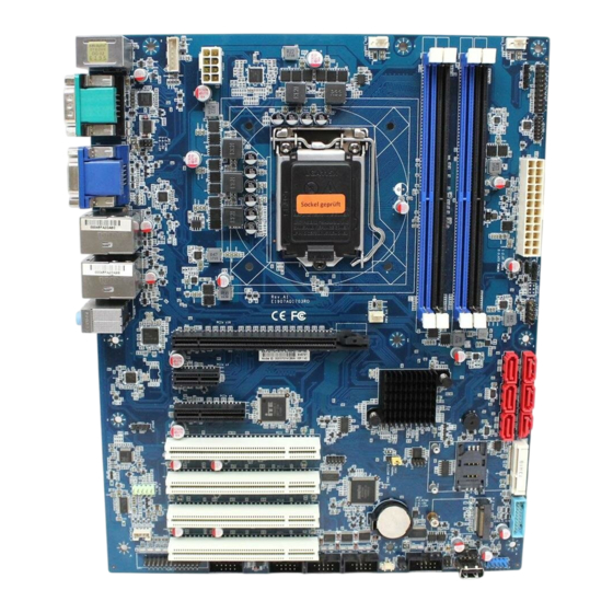
Page 16: Product Overview
EAX-Q170P User’s Manual 2.1 Product Overview 16 EAX-Q170P User’s Manual... -
Page 17: Jumper And Connector List
4 x 1 wafer, pitch 2.54mm function supported) SYSFAN3 System fan connector 2 3 x 1 wafer, pitch 2.54mm JFP1 Miscellaneous setting connector 5 x 2 header, pitch 2.54 mm DIMM1/2/3/4 288-pin DDR4 DIMM socket AUDIO1 Audio connector EAX-Q170P User’s Manual 17... - Page 18 VGA1 VGA connector NGFF1 M.2 2230 KeyA Slot support WiFi module 13 x 2 header, pitch 2.54mm LPT1 LPT connector JSIM1 SIM card slot JSPDIF1 S/PDIF connector 5 x 1 header, pitch 2.54mm JSMB1 SMBus connector 18 EAX-Q170P User’s Manual...
-
Page 19: Setting Jumpers & Connectors
User’s Manual 2.3 Setting Jumpers & Connectors 2.3.1 Serial port 1 pin9 signal select (JRI1) Ring* +12V * Default 2.3.2 Serial port 2 pin9 signal select (JRI2) Ring* +12V * Default EAX-Q170P User’s Manual 19... -
Page 20: At/Atx Power Mode Select (Jatatx1)
EAX-Q170P User’s Manual 2.3.3 AT/ATX Power Mode Select (JATATX1) * Default 2.3.4 Clear CMOS (JCMOS1) Protect* Clear CMOS * Default 20 EAX-Q170P User’s Manual... -
Page 21: Serial Port 2 Connector (Jcom2A)
User’s Manual 2.3.5 Serial port 2 connector (JCOM2A) Signal PIN PIN Signal 2.3.6 COM2 RS485/422 connector (JCOM2B) Signal PIN PIN Signal 485TX- 422RX- 485TX+ 422RX+ EAX-Q170P User’s Manual 21... -
Page 22: Serial Port 3/4/5/6 Connector (Jcom3/4/5/6)
EAX-Q170P User’s Manual 2.3.7 Serial port 3/4/5/6 connector (JCOM3/4/5/6) Signal PIN PIN Signal 2.3.8 General purpose I/O connector (JDIO1) Signal PIN PIN Signal SMB_CLK_9555 10 SMB_DATA_9555 22 EAX-Q170P User’s Manual... -
Page 23: Sgpio Connector (Jsgpio1)
User’s Manual 2.3.9 SGPIO connector (JSGPIO1) Signal PIN PIN Signal SGIO_LOAD SGIO_DATOUT0 SGIO_CLK SGIO_DATOUT1 2.3.10 ATX Power connector (ATXPWR1) Signal Signal +3.3V +12V +12V +V5SB ATX_PWRGD ATX_PSON# +3.3V -12V +3.3V +3.3V EAX-Q170P User’s Manual 23... -
Page 24: Power Connector (Atx12V1)
EAX-Q170P User’s Manual 2.3.11 Power connector (ATX12V1) Signal PIN PIN Signal +12V +12V +12V +12V 2.3.12 SMBus connector (JSMB1) Signal SMB_CLK_MAIN SMB_DATA_MAIN SMB_ALERT#_MAIN +3.3V 24 EAX-Q170P User’s Manual... -
Page 25: Usb Connector 1 (Jusb1)
User’s Manual 2.3.13 USB connector 1 (JUSB1) Signal PIN PIN Signal USB_R_DP14 USB_R_DP13 USB_R_DN14 USB_R_DN13 SS_USB_TXP_C_6 SS_USB_TXP_C_5 15 SS_USB_TXN_C_6 SS_USB_TXN_C_5 17 SS_USB_RXP_C_6 SS_USB_RXP_C_5 18 SS_USB_RXN_C_6 SS_USB_RXN_C_5 USBVCC_DE USBVCC_DE 2.3.14 USB connector 2 (JUSB2) Signal USBVCC56 USB_R_DN5 USB_R_DP5 EAX-Q170P User’s Manual 25... -
Page 26: Usb Connector 4 (Jusb4)
EAX-Q170P User’s Manual 2.3.15 USB connector 4 (JUSB4) Signal Signal USBVCC_BC USBVCC_BC USB_R_DN12 USB_R_DN11 USB_R_DP12 USB_R_DP11 2.3.16 Battery connector (JBAT1) Signal RTC_VBAT_1 26 EAX-Q170P User’s Manual... -
Page 27: Audio Connector (Jaudio1)
2.3.17.1 Signal Description –Audio connector (JAUDIO1) Signal Signal Description LINE2_JD AUDIO IN (LINE_RIN/LIN)sense pin MIC2_JD MIC IN (MIC_RIN/LIN) sense pin 2.3.18 LPC connector (JLPC1) Signal PIN PIN Signal LPC_AD0_R +3.3V LPC_AD1_R BUF_PLT_RST# LPC_AD2_R LPC_FRAME#_R LPC_AD3_R LPC_CLK LPC_SERIRQ_R EAX-Q170P User’s Manual 27... -
Page 28: Spi Connector (Jspi1)
EAX-Q170P User’s Manual 2.3.19 SPI connector (JSPI1) Signal PIN PIN Signal +3.3V SSPI_CS0#_R SSPI_SCLK_R SSPI_SO_R SSPI_SI_R SSPI_HOLD#0 2.3.20 Speaker connector (JSPK1) Signal SPK_L+ SPK_L- SPK_R+ SPK_R- 28 EAX-Q170P User’s Manual... -
Page 29: Miscellaneous Setting Connector (Jfp1)
User’s Manual 2.3.21 Miscellaneous setting connector (JFP1) Signal PIN PIN Signal HDD_LED+ PWR_LED+ HDD_LED- PWE_LED- RSET_BTN# PWRBTN# 2.3.22 CPU fan connector (CPUFAN1) Signal +12V CPUFANIN CPUFANOUT EAX-Q170P User’s Manual 29... -
Page 30: System Fan Connector 1 (Sysfan1)
EAX-Q170P User’s Manual 2.3.23 System fan connector 1 (SYSFAN1) Signal +12V SYSFANIN1 SYSFANOUT1 2.3.24 System fan connector 2 (SYSFAN3) Signal +12V SYS_FAN_IN_2 30 EAX-Q170P User’s Manual... -
Page 31: Ps/2 Keyboard & Mouse Connector (Jkbms1)
User’s Manual 2.3.25 PS/2 keyboard & mouse connector (JKBMS1) Signal MSCK MSDT KBDT KBCK 2.3.26 S/PDIF connector (JSPDIF1) Signal SPDIF_O EAX-Q170P User’s Manual 31... -
Page 32: External Speaker Connector (Jbz1)
EAX-Q170P User’s Manual 2.3.27 External Speaker connector (JBZ1) Signal 2.3.28 LPT connector (LPT1) Signal PIN PIN Signal PT-STB- PT_AFD# PTD0 ERR# PTD1 PT_PAR_INIT# PTD2 PT_SLIN# PTD3 PTD4 PTD5 PTD6 PTD7 ACK# BUSY SLCT 32 EAX-Q170P User’s Manual... -
Page 33: Auxiliary Panel Connector (Jauxp1)
User’s Manual 2.3.29 Auxiliary Panel connector (JAUXP1) Signal PIN PIN Signal SMB_CLK_MAIN CASEOPEN# ERROR_LED SMB_DATA_MAIN ERROR_LED# FRONT_LAN1_ACT 13 FRONT_LAN1_LINK100# 16 FRONT_LAN1_LINK1000# FRONT_LAN2_ACT 17 FRONT_LAN2_LINK100# 20 FRONT_LAN2_LINK1000# EAX-Q170P User’s Manual 33... -
Page 34: Bios Setup
EAX-Q170P User’s Manual 3.BIOS Setup 34 EAX-Q170P User’s Manual... -
Page 35: Introduction
If you do not press the keys at the correct time and the system does not boot, an error message will be displayed and you will again be asked to. Press F1 to Continue, DEL to enter SETUP EAX-Q170P User’s Manual 35... -
Page 36: Using Setup
Note: Some of the navigation keys differ from one screen to another. To Display a Sub Menu Use the arrow keys to move the cursor to the sub menu you want. Then press <Enter>. A “” pointer marks all sub menus. 36 EAX-Q170P User’s Manual... -
Page 37: Getting Help
BIOS Vendor and your systems manufacturer to provide the absolute maximum performance and reliability. Even a seemingly small change to the chipset setup has the potential for causing you to use the override. EAX-Q170P User’s Manual 37... -
Page 38: Bios Setup
Note: The BIOS setup screens shown in this chapter are for reference purposes only, and may not exactly match what you see on your screen. Visit the Avalue website (www.avalue.com.tw) to download the latest product and BIOS information. 38 EAX-Q170P User’s Manual... -
Page 39: Advanced Menu
3.6.2.1 Trusted Computing Item Options Description Enables or Disables BIOS support for security Disable, Security Device Support device. O.S. will not show Security Device. TCG EFI Enable[Default] protocol and INT1Ainterface will not be available. EAX-Q170P User’s Manual 39... -
Page 40: Apci Settings
Enable/Disable system waked up by Ring Wake Up by Ring Enabled[Default], signal from standby states (S3~S5). Enable/Disable USB Power delivery in S3 Disabled USB Power state in S3-S5 (Sleep), S4 (Hibernate) and S5 (Soft Off) Enabled[Default], States. 40 EAX-Q170P User’s Manual... -
Page 41: Amt Configuration
Extension. Note: iAMT H/W is always enabled. This option just Intel AMT Enabled[Default], controls the BIOS extension execution. If enabled, this requires additional firmware in the SPI device. Disabled[Default], Un-Configure ME OEMFlag Bit 15: Un-Configure ME without password. Enabled 3.6.2.4 PCH-FW Configuration EAX-Q170P User’s Manual 41... -
Page 42: Firmware Update Configuration
PTT – Intel Platform Trust Technology. Warning! If TPM Device Selection PTT/dTPM was disabled, All data saved on it will be lost. 3.6.2.4.1 Firmware Update Configuration Item Option Description Disabled[Default], ME FW Image Re-Flash Enable/Disable Me FW Image Re-Flash function. Enabled 42 EAX-Q170P User’s Manual... -
Page 43: Super Io Configuration
Set Parameters of Serial Port 4 (COMD). Serial Port 5 Configuration Set Parameters of Serial Port 5 (COME). Serial Port 6 Configuration Set Parameters of Serial Port 6 (COMF). Parallel Port Configuration Set Parameters of Parallel Port (LPT/LPTE). EAX-Q170P User’s Manual 43... -
Page 44: Serial Port 1 Configuration
Enable or Disable Serial Port (COM). Disabled Change Settings Auto[Default] Select an optimal setting for Super IO Device. 3.6.2.5.2 Serial Port 2 Configuration Item Option Description Enabled[Default], Serial Port Enable or Disable Serial Port (COM). Disabled 44 EAX-Q170P User’s Manual... -
Page 45: Serial Port 3 Configuration
Set COM Port as RS232, RS422 or RS485 mode. RS485 3.6.2.5.3 Serial Port 3 Configuration Item Option Description Enabled[Default], Serial Port Enable or Disable Serial Port (COM). Disabled Change Settings Auto[Default] Select an optimal setting for Super IO Device. 3.6.2.5.4 Serial Port 4 Configuration EAX-Q170P User’s Manual 45... -
Page 46: Serial Port 5 Configuration
Select an optimal setting for super IO Device. 3.6.2.5.5 Serial Port 5 Configuration Item Option Description Enabled[Default], Serial Port Enable or Disable Serial Port (COM). Disabled Change Settings Auto[Default] Select an optimal setting for super IO Device. 46 EAX-Q170P User’s Manual... -
Page 47: Serial Port 6 Configuration
Serial Port Enable or Disable Serial Port (COM). Disabled Change Settings Auto[Default] Select an optimal setting for super IO Device. 3.6.2.5.7 Parallel Port Configuration Item Option Description Parallel Port Enabled[Default], Enable or Disable Parallel Port (LPT/LPTE). EAX-Q170P User’s Manual 47... -
Page 48: Nct6106D H/W Monitor
SPP Mode EPP-1.9 and SPP Mode Device Mode EPP-1.7 and SPP Mode Change the Printer Port mode. ECP Mode ECP and EPP 1.9 Mode ECP and EPP 1.7 Mode 3.6.2.6 NCT6106D H/W Monitor 3.6.2.6.1 Smart Fan Configuration 48 EAX-Q170P User’s Manual... -
Page 49: S5 Rtc Wake Settings
Enable or disable System wake on alarm event. Select Disabled[Default], Fixed Time, system will wake on the hr::min::sec Wake system from S5 Fixed Time specified. Select Dynamic Time, System will wake on Dynamic Time the current time + Increase minute(s). EAX-Q170P User’s Manual 49... -
Page 50: Serial Port Console Redirection
Disabled[Default], Console Redirection Console Redirection Enable or Disable. Enabled 3.6.2.8.1 Legacy Console Redirection Settings Item Option Description Select a COM port to display redirection of Legacy Serial Redirection Port COM1[Default] Legacy OS and Legacy OPROM Messages. 50 EAX-Q170P User’s Manual... -
Page 51: Cpu Configuration
Number of cores to enable in each processor Active Processor Cores package. When enabled, a VMM can utilize the Disabled Intel Virtualization Technology additional hardware capabilities provided by Enabled[Default], Vanderpool Technology. Intel® SpeedStep™ Disabled Allows more than two frequency ranges to be EAX-Q170P User’s Manual 51... -
Page 52: Intel Txt Configuration
EAX-Q170P User’s Manual Enabled[Default], supported. Disabled Turbo Mode Turbo Mode. Enabled[Default], Disabled CPU C states Enable or disable CPU states. Enabled[Default], C0/C1 Package C State limit Package C State limit. AUTO[Default] 3.6.2.10 Intel TXT Configuration 52 EAX-Q170P User’s Manual... -
Page 53: Sata Configuration
User’s Manual 3.6.2.11 SATA Configuration Item Options Description Disabled, SATA Controller(s) Enable or disable SATA Device. Enabled[Default] AHCI[Default] SATA Mode Selection Determines how SATA controller(s) operate. RAID Disabled, SATA Port Enable or Disable SATA Port. Enabled[Default] EAX-Q170P User’s Manual 53... -
Page 54: Software Feature Mask Configuration
If enabled, indicates that the HDD password unlock HDD Unlock Enabled[Default], in the OS is enabled. If enabled, indicates that the LED/SGPIO hardware Disabled LED Locate is attached and ping to locate feature is enabled on Enabled[Default], the OS. 54 EAX-Q170P User’s Manual... -
Page 55: Ami Graphic Output Protocol Policy
User’s Manual 3.6.2.12 AMI Graphic Output Protocol Policy 3.6.2.13 Network Stack Configuration Item Options Description Enabled Network Stack Enable/Disable UEFI Network Stack. Disabled[Default] EAX-Q170P User’s Manual 55... -
Page 56: Csm Configuration
EAX-Q170P User’s Manual 3.6.2.14 CSM Configuration Item Options Description Enabled CSM Support Enable/Disable CSM Support. Disabled[Default] 3.6.2.15 USB Configuration The USB Configuration menu helps read USB information and configures USB settings. 56 EAX-Q170P User’s Manual... -
Page 57: Chipset
Floppy enumerates devices according to their media format. Optical drives are emulated as ‘CDROM’, Mass Storage Devices Forced FDD Hard Disk drives with no media will be emulated according CD-ROM to a drive type. 3.6.3 Chipset EAX-Q170P User’s Manual 57... -
Page 58: System Agent (Sa) Configuration
Description Enabled[Default] VT-d VT-d capability. Disabled 3.6.3.1.1 Graphics Configuration Item Option Description Enabled If Enable, it will not scan for External Gfx Skip Scanning of External Gfx Card Disabled[Default] Card on PEG and PCH PCIE Ports. 58 EAX-Q170P User’s Manual... -
Page 59: Dmi/Opi Configuration
IGFX Primary Display device should be Primary Display Or select SG for Switchable Gfx. PCIE Auto [Default] Keep IGFX enabled based on the setup Internal Graphics Disabled options. Enabled 3.6.3.1.2 DMI/OPI Configuration 3.6.3.1.3 PEG Port Configuration EAX-Q170P User’s Manual 59... -
Page 60: Memory Configuration
Program PCIe ASPM after OpROM after OpROM. Disabled: PCIe ASPM will be Enabled programmed before OpROM. 3.6.3.1.4 Memory Configuration Item Option Description Auto[Default] 1067/1200/1333/1400/1600 Maximum Memory Maximum Memory Frequency Selections in /1800/1867/2000/2133/2200 Frequency Mhz. /2400/2600/2667/2800/2933 /3000/3200 60 EAX-Q170P User’s Manual... -
Page 61: Gt - Power Management Control
3.6.3.1.5 GT – Power Management Control Item Option Description Disabled RC6 (Render Standby) Check to enable render standby support. Enabled[Default] 3.6.3.2 PCH-IO Configuration Item Option Description Disabled Enable or disable OnBoard PCH LAN PHY LAN PHY Controller Enabled[Default] Controller. EAX-Q170P User’s Manual 61... -
Page 62: Pci Express Configuration
EAX-Q170P User’s Manual Quiet Serial IRQ Mode Configure Serial IRQ Mode. Continuous[Default] 3.6.3.2.1 PCI Express Configuration 3.6.3.2.1.1 PCI-E Root Port 1: PCIe x4 Slot Item Option Description Enabled[Default], PCIe x4 Slot Control the PCI Express Root Port. Disabled 62 EAX-Q170P User’s Manual... - Page 63 DISABLE – Disables ASPM. L0sL1 Auto[Default] Auto[Default] Gen1 PCIe Speed Select PCI Express port speed. Gen2 Gen3 Detect Non-Compliance PCI Express Disabled[Default], Detect Non-Compliance Device Device. If enable, it will take more time at Enabled POST time. EAX-Q170P User’s Manual 63...
- Page 64 EAX-Q170P User’s Manual 3.6.3.2.1.3 PCI-E Root Port 6: PCI-E to PCI Bridge Item Option Description Enabled[Default], PCI-E to PCI Bridge Control the PCI Express Root Port. Disabled 3.6.3.2.1.4 PCI-E Root Port 7: PCIe x1 Slot 64 EAX-Q170P User’s Manual...
- Page 65 Device. If enable, it will take more time at Enabled POST time. 3.6.3.2.1.5 PCI-E Root Port 8: Intel I211AT LAN Chip Item Option Description Enabled[Default], Intel I211AT LAN Chip Control the PCI Express Root Port. Disabled EAX-Q170P User’s Manual 65...
- Page 66 DISABLE – Disables ASPM. L0sL1 Auto Auto[Default] Gen1 PCIe Speed Select PCI Express port speed. Gen2 Gen3 Detect Non-Compliance PCI Express Disabled[Default], Detect Non-Compliance Device Device. If enable, it will take more time at Enabled POST time. 66 EAX-Q170P User’s Manual...
- Page 67 DISABLE – Disables ASPM. L0sL1 Auto[Default] Auto[Default] Gen1 PCIe Speed Select PCI Express port speed. Gen2 Gen3 Detect Non-Compliance PCI Express Disabled[Default], Detect Non-Compliance Device Device. If enable, it will take more time at Enabled POST time. EAX-Q170P User’s Manual 67...
-
Page 68: Save And Exit
This option restores all BIOS settings to the factory default. This option is useful if the controller exhibits unpredictable behavior due to an incorrect or inappropriate BIOS setting. 3.6.4.4 Launch EFI Shell from filesystem device Attempts to Launch EFI Shell application (Shellx64.efi) from one of the available filesystem devices. 68 EAX-Q170P User’s Manual... -
Page 69: Drivers Installation
User’s Manual 4. Drivers Installation Note: Installation procedures and screen shots in this section are for your reference and may not be exactly the same as shown on your screen. EAX-Q170P User’s Manual 69... -
Page 70: Install Chipset Driver
Windows 10 operation system. If the warning message appears while the installation process, click Continue to go on. Step 3. Click Install. Step1. Click Next. Step 4. Complete setup. Step 2. Click Accept. 70 EAX-Q170P User’s Manual... -
Page 71: Install Vga Driver
Windows 10 operation system. Step 3. Click Next. Step 1. Click Next to continue installation. Step 4. Click Next. Step 5. Click Finish to complete setup. Step 2. Click Yes to accept license agreement. EAX-Q170P User’s Manual 71... -
Page 72: Install Me Driver
Note: The installation procedures and screen shots in this section are based on Windows 10 operation system. Step 3. Click Next Step 4. Click Finish to complete the setup Step 1. Click Next to continue setup. Step 2. Click Next. 72 EAX-Q170P User’s Manual... -
Page 73: Install Audio Driver (For Realtek Alc892 Hd Audio)
Windows 10 operation system. If the warning message appears while the installation process, click Continue to go on. Step1. Click Next to Install. Step 2. Select Finish to complete Installation. EAX-Q170P User’s Manual 73... -
Page 74: Install Lan Driver
Windows 10 operation system. Step 3. Click Next. Step 1. Click Next to continue installation. Step 4. Click Install. Step 2. Click Next. Step 5. Click Finish to complete setup. 74 EAX-Q170P User’s Manual... -
Page 75: Install Rst Driver
Windows 10 operation system. Step 3. Click Next. Step 1. Click Next to continue installation. Step 4. Click Next. Step 2. Click Next. Step 5. Click Finish to complete setup. EAX-Q170P User’s Manual 75... - Page 76 EAX-Q170P User’s Manual Step 6. Click Finish to complete setup. 76 EAX-Q170P User’s Manual...
-
Page 77: Mechanical Drawing
User’s Manual 5. Mechanical Drawing EAX-Q170P User’s Manual 77... - Page 78 EAX-Q170P User’s Manual Unit: mm 78 EAX-Q170P User’s Manual...
- Page 79 User’s Manual Unit: mm EAX-Q170P User’s Manual 79...
Need help?
Do you have a question about the EAX-Q170P and is the answer not in the manual?
Questions and answers