
Related Manuals for Avalue Technology EAX-C246P


Summary of Contents for Avalue Technology EAX-C246P
- Page 1 EAX-C246P Intel® 8/9th Generation Core™ Processor ATX Motherboard With Intel® C246 Chipset User’s Manual Ed – 20 August 2019 Part No. E2047NPDP02R...
- Page 2 Disclaimer Avalue Technology Inc. reserves the right to make changes, without notice, to any product, including circuits and/or software described or contained in this manual in order to improve design and/or performance. Avalue Technology assumes no responsibility or liability for the...
- Page 3 Applications that are described in this manual are for illustration purposes only. Avalue Technology Inc. makes no representation or warranty that such application will be suitable for the specified use without further testing or modification.
- Page 4 A product returned without proof of the purchase date is not eligible for warranty service. Write the RMA number visibly on the outside of the package and ship it prepaid to your dealer. 4 EAX-C246P User’s Manual...
-
Page 5: Table Of Contents
2.3.20 S/PDIF connector (JSPDIF1) ......................30 2.3.21 External Speaker connector (JBZ1) ....................31 2.3.22 Auxiliary Panel connector (JAUXP1) ..................... 31 2.3.23 Serial port 2 connector (COM2)..................... 32 2.3.24 USB connector (USB1) ........................32 2.3.25 J1RS1 connector (J1RS1) ......................33 EAX-C246P User’s Manual... - Page 6 3.6.2.5.8 Serial Port 8 Configuration ....................55 3.6.2.5.9 Serial Port 9 Configuration ....................56 3.6.2.5.10 Serial Port 10 Configuration ....................56 3.6.2.6 NCT6106D H/W Monitor ......................57 3.6.2.6.1 Smart Fan Configuration ....................... 57 3.6.2.7 S5 RTC Wake Settings ......................59 6 EAX-C246P User’s Manual...
- Page 7 Launch EFI Shell from filesystem device ................82 4. Drivers Installation....................... 83 Install Chipset Driver ....................84 Install VGA Driver ....................85 Install ME Driver ...................... 86 Install Audio Driver (For Realtek ALC892 HD Audio) ..........87 Install LAN Driver ....................88 EAX-C246P User’s Manual...
- Page 8 EAX-C246P User’s Manual Install RST Driver ....................90 5. Mechanical Drawing ....................92 8 EAX-C246P User’s Manual...
-
Page 9: Getting Started
1.2 Packing List Before you begin installing your single board, please make sure that the following materials have been shipped: 1 x EAX-C246P motherboard 2 x SATA cables 1 x I/O Shield ... -
Page 10: Document Amendment History
EAX-C246P User’s Manual 1.3 Document Amendment History Revision Date Comment January 2019 Avalue Initial Release May 2019 Avalue Update Jumper and Connector August 2019 Avalue Update System Specifications 10 EAX-C246P User’s Manual... -
Page 11: Manual Objectives
We strongly recommend that you study this manual carefully before attempting to set up EAX-C246P or change the standard configurations. Whilst all the necessary information is available in this manual we would recommend that unless you are confident, you contact your supplier for guidance. -
Page 12: System Specifications
DP: 4096 x 2304@60Hz Multiple Display Triple Display HDMI HDMI: 3840 x 2160 @ 30 Hz, 2560 x 1600@ 30 Hz Ethernet Ethernet 6W Amplifier Interface Audio Codec Realtek ALC892 HD Audio Decoding Controller Internal I/O Connectors 12 EAX-C246P User’s Manual... - Page 13 1 x 2 x 10 pin, pitch 2.00mm connector for GPIO: 16 bits & +5VS Level SMBus 1 x 5 pin, pitch 2.54mm connector for +3.3S Level SMBus 1 x 2 x 4 pin, pitch 2.00mm connector for BIOS SPI 2 x 2 x 5 pin, pitch 2.0mm connector for LPC EAX-C246P User’s Manual 13...
- Page 14 80x70mm) Weight 0.60 kg BIOS Support: OS Support 1. Win10 64bit UEFI (listed in accordance Intel® LGA1151 Socket Supports 8th Generation CPU with Intel document) 2. Linux Note: Specifications are subject to change without notice. 14 EAX-C246P User’s Manual...
-
Page 15: Architecture Overview-Block Diagram
User’s Manual 1.6 Architecture Overview—Block Diagram The following block diagram shows the architecture and main components of EAX-C246P. EAX-C246P User’s Manual 15... -
Page 16: Hardware Configuration
EAX-C246P User’s Manual 2. Hardware Configuration 16 EAX-C246P User’s Manual... -
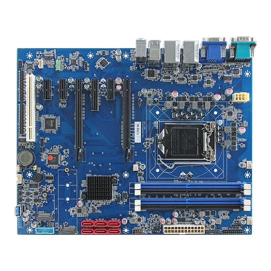
Page 17: Product Overview
User’s Manual 2.1 Product Overview EAX-C246P User’s Manual 17... -
Page 18: Jumper And Connector List
Function Note 4 x 1 wafer, pitch 2.54mm CPUFAN1 CPU fan connector System fan connector 1 SYSFAN1 4 x 1 wafer, pitch 2.54mm (with smart fan function supported) JFP1 5 x 2 header, pitch 2.54 mm 18 EAX-C246P User’s Manual... - Page 19 Serial ATA connector 1~6 HDMI1 HDMI connector DP connector VGA1 VGA connector M.2 Key A M2KA1 M.2 Key M M2KM1 S/PDIF connector 4 x 1 header, pitch 2.54mm JSPDIF1 JSMB1 SMBus connector 5 x 1 header, pitch 2.54mm EAX-C246P User’s Manual 19...
- Page 20 EAX-C246P User’s Manual Note: 1 x PCI-e x16* Default (PCIEX1) - ONLY this slot is working 2 x PCI-e x8 (By BOM option) - PCIEX1 and PCIEX2 both working 20 EAX-C246P User’s Manual...
-
Page 21: Setting Jumpers & Connectors
User’s Manual 2.3 Setting Jumpers & Connectors 2.3.1 Serial port 3 pin9 signal select (JRI3) Ring* +12V * Default 2.3.2 Serial port 2 pin9 signal select (JRI2) Ring* +12V * Default EAX-C246P User’s Manual 21... -
Page 22: Serial Port 1 Pin9 Signal Select (Jri1)
EAX-C246P User’s Manual 2.3.3 Serial port 1 pin9 signal select (JRI1) Ring* +12V * Default 2.3.4 JME1 connector (JME1) Enable ME * Disable ME * Default 22 EAX-C246P User’s Manual... -
Page 23: Clear Cmos (Jcmos1)
User’s Manual 2.3.5 Clear CMOS (JCMOS1) Protect* Clear CMOS * Default 2.3.6 JPGE1 connector (JPGE1) PIXE X16 * PIXE X8 * Default EAX-C246P User’s Manual 23... -
Page 24: At/Atx Power Mode Select (Jsatx1)
EAX-C246P User’s Manual 2.3.7 AT/ATX Power Mode Select (JSATX1) * Default 2.3.8 General purpose I/O connector (DIO1) Signal PIN PIN Signal 5V_SMB_CLK 5V_SMB_DATA 24 EAX-C246P User’s Manual... -
Page 25: Atx Power Connector (Atxpwr1)
User’s Manual 2.3.9 ATX Power connector (ATXPWR1) Signal PIN PIN Signal +3.3V +3.3V +3.3V -12V 16 ATX_PSON# ATX24_PWROK +V5SB +12V +12V +3.3V 2.3.10 Power connector (ATX12V1) Signal PIN PIN Signal +12V +12V +12V +3.3V +12V EAX-C246P User’s Manual 25... -
Page 26: Smbus Connector (Jsmb1)
EAX-C246P User’s Manual 2.3.11 SMBus connector (JSMB1) Signal SMB_CLK SMB_DATA SMB_ALERT# +3.3V 2.3.12 USB connector 1 (JUSB1) Signal PIN PIN Signal +5V_USB4-1 +V5A_USB4-1 USB30_RX_N1 USB30_RX_N2 18 USB30_RX_P1 USB30_RX_P2 17 USB30_TXN1 USB30_TXN2 USB30_TXP1 USB30_TXP2 USB_N5 USB_N6 USB_P5 USB_P6 26 EAX-C246P User’s Manual... -
Page 27: Battery Connector (Bat2)
User’s Manual 2.3.13 Battery connector (BAT2) Signal +3.3V 2.3.14 LPC connector (JLPC1) Signal PIN PIN Signal LPC_SERIRQ LPC_DEG_CLK LPC_AD3 LPC_FRAME# LPC_AD2 PLT_RST#_BUF LPC_AD1 +3.3V LPC_AD0 EAX-C246P User’s Manual 27... -
Page 28: Spi Connector (Spi1)
EAX-C246P User’s Manual 2.3.15 SPI connector (SPI1) Signal PIN PIN Signal +3.3V SPI_CS0# SPI_CLK SPI_MISO SPI_MOSI SPI_HOLD# 2.3.16 Speaker connector (SPK1) Signal LSPK+ LSPK- RSPK+ RSPK- 28 EAX-C246P User’s Manual... -
Page 29: Jfp1 Connector (Jfp1)
User’s Manual 2.3.17 JFP1 connector (JFP1) Signal PIN PIN Signal HDD_LED+ PWR_LED+ HDD_LED- PWR_LED- SYS_RST# PWRBTN# 2.3.18 CPU fan connector (CPUFAN1) Signal +12V CPU_R_FANIN CPU_FANOUT EAX-C246P User’s Manual 29... -
Page 30: System Fan Connector 1 (Sysfan1)
EAX-C246P User’s Manual 2.3.19 System fan connector 1 (SYSFAN1) Signal +12V SYS_R_FANIN SYS_FANOUT 2.3.20 S/PDIF connector (JSPDIF1) Signal SPDIF_OUT 30 EAX-C246P User’s Manual... -
Page 31: External Speaker Connector (Jbz1)
User’s Manual 2.3.21 External Speaker connector (JBZ1) Signal 2.3.22 Auxiliary Panel connector (JAUXP1) Signal PIN PIN Signal SMB_CLK CASEOPEN# ERROR_LED+ SMB_DATA ERROR_LED- FRONT_LAN1_ACT 13 FRONT_LAN1_LINK100# 16 FRONT_LAN1_LINK1000# FRONT_LAN2_ACT 17 FRONT_LAN2_LINK100# 20 FRONT_LAN2_LINK1000# EAX-C246P User’s Manual 31... -
Page 32: Serial Port 2 Connector (Com2)
EAX-C246P User’s Manual 2.3.23 Serial port 2 connector (COM2) Signal PIN PIN Signal NDCDB# NRXDB NTXDB NDTRB# NDSRB# NRTSB# NCTSB# NRIB# 2.3.24 USB connector (USB1) Signal PIN PIN Signal USB_10P USB_9P USB_10N USB_9N 32 EAX-C246P User’s Manual... -
Page 33: J1Rs1 Connector (J1Rs1)
User’s Manual 2.3.25 J1RS1 connector (J1RS1) Signal PIN PIN Signal +V5S A422RX+ A485TX+ A422RX- A485TX- 2.3.26 J1RS2 connector (J1RS2) Signal PIN PIN Signal +V5S B422RX+ B485TX+ B422RX- B485TX- EAX-C246P User’s Manual 33... -
Page 34: Faud1 Connector (Faud1)
EAX-C246P User’s Manual 2.3.27 FAUD1 connector (FAUD1) Signal PIN PIN Signal MIC2_LIN MIC2_RIN ACZ_DET# LINE2_RIN MIC2_JD SENSE_B LINE2_LIN LINE2_JD 2.3.28 AUXFAN1 connector (AUXFAN1) Signal +12V AUX_R_FANIN 34 EAX-C246P User’s Manual... -
Page 35: Serial Port Connector (4Com1)
Signal PIN PIN Signal NDCDC# NRXDC NTXDC NDTRC# NDSRC# NRTSC# NCTSC# NRIC# NDCDD# NRXDD NTXDD NDTRD# NDSRD# NRTSD# NCTSD# NRID# NDCDE# NRXDE NTXDE NDTRE# NDSRE# NRTSE# NCTSE# NRIE# NDCDF# NRXDF NTXDF NDTRF# NDSRF# NRTSF# NCTSF# NRIF# EAX-C246P User’s Manual 35... -
Page 36: Serial Port Connector (4Com2)
Signal PIN PIN Signal NDCD1# NRXD1 NTXD1 NDTR1# NDSR1# NRTS1# NCTS1# NRI1# NDCD2# NRXD2 NTXD2 NDTR2# NDSR2# NRTS2# NCTS2# NRI2# NDCD3# NRXD3 NTXD3 NDTR3# NDSR3# NRTS3# NCTS3# NRI3# NDCD4# NRXD4 NTXD4 NDTR4# NDSR4# NRTS4# NCTS4# NRI4# 36 EAX-C246P User’s Manual... -
Page 37: Pci-E X16 / Pci-E X8 Slot (Pciex1 / Pciex2)
+3.3V B10 A10 +3.3V PCIEX16X8_WAKE# B11 A11 PLT_RST#_BUF PCIEX16_CLKREQ# B12 A12 B13 A13 PCIEX16_CLKP PEG1_TXP0 B14 A14 PCIEX16_CLKN PEG1_TXN0 B15 A15 B16 A16 PEG1_RXP0 PCIEX16_CLKREQ# B17 A17 PEG1_RXN0 B18 A18 PEG1_TXP1 B19 A19 PEG1_TXN1 B20 A20 EAX-C246P User’s Manual 37... - Page 38 PEG1_RXP7 PEG2_TXP7 PEG1_RXN7 PEG2_TXN7 A80 X16_PEG2_RXP7 PEG2_TXP0 A81 X16_PEG2_RXN7 PEG2_TXN0 Note: 1 x PCI-e x16* Default (PCIEX1) - ONLY this slot is working 2 x PCI-e x8 (By BOM option) - PCIEX1 and PCIEX2 both working 38 EAX-C246P User’s Manual...
-
Page 39: Ps/2 Keyboard & Mouse Connector (Kbms1)
User’s Manual 2.3.32 PS/2 keyboard & mouse connector (KBMS1) Signal PIN PIN Signal MSCK MSDAT KBCK KBDAT EAX-C246P User’s Manual 39... -
Page 40: Bios Setup
EAX-C246P User’s Manual 3.BIOS Setup 40 EAX-C246P User’s Manual... -
Page 41: Introduction
If you do not press the keys at the correct time and the system does not boot, an error message will be displayed and you will again be asked to. Press F1 to Continue, DEL to enter SETUP EAX-C246P User’s Manual 41... -
Page 42: Using Setup
Note: Some of the navigation keys differ from one screen to another. To Display a Sub Menu Use the arrow keys to move the cursor to the sub menu you want. Then press <Enter>. A “” pointer marks all sub menus. 42 EAX-C246P User’s Manual... -
Page 43: Getting Help
BIOS Vendor and your systems manufacturer to provide the absolute maximum performance and reliability. Even a seemingly small change to the chipset setup has the potential for causing you to use the override. EAX-C246P User’s Manual 43... -
Page 44: Bios Setup
<Enter> to accept and enter the sub-menu. 3.6.1 Main Menu This section allows you to record some basic hardware configurations in your computer and set the system clock. 44 EAX-C246P User’s Manual... -
Page 45: System Language
Visit the Avalue website (www.avalue.com.tw) to download the latest product and BIOS information. 3.6.2 Advanced Menu This section allows you to configure your CPU and other system devices for basic operation through the following sub-menus. EAX-C246P User’s Manual 45... -
Page 46: Cpu Configuration
Item Options Description When enabled, a VMM can utilize the Intel (VMX) Virtualization Disabled additional hardware capabilities provided by Technology Enabled[Default], Vanderpool Technology. All[Default], Number of cores to enable in each processor Active Processor Cores package. 46 EAX-C246P User’s Manual... -
Page 47: Cpu - Power Management Control
Disabled C-State Auto Demotion Configure C-State Auto Demotion C1 and C3[Default], Disabled C-State Un-demotion Configure C-State Un-demotion C1 and C3[Default], Disabled[Default], Package C-State Demotion Package C-State Demotion Enabled Disabled[Default], Package C-State Un-demotion Package C-State Un-demotion Enabled EAX-C246P User’s Manual 47... -
Page 48: Pch-Fw Configuration
Options Description When disabled AMT BIOS Feature are no longer Disabled supported and user is no longer able to access MEBx AMT BIOS Features Enabled[Default], Setup. Note: This option does not disable Manageability Features in FW. 48 EAX-C246P User’s Manual... -
Page 49: Oem Flags Settings
Extended User OEMFlag Bit 15: Unconfigure ME with resetting Unconfigure ME USER MEBx password to default. Supervisor 3.6.2.2.2 Firmware Update Configuration Item Option Description Disabled[Default], Me FW Image Re-Flash Enable/Disable Me FW Image Re-Flash function. Enabled EAX-C246P User’s Manual 49... -
Page 50: Trusted Computing
O.S. will not show Security Device. TCG EFI Enable[Default] protocol and INT1A interface will not be available. 3.6.2.4 APCI Settings Item Options Description Enable ACPI Auto Disabled[Default], Enables or Disables BIOS ACPI Auto Configuration Enabled Configuration. 50 EAX-C246P User’s Manual... -
Page 51: Super Io Configuration
Set Parameters of Serial Port 7 (COMG). Serial Port 8 Configuration Set Parameters of Serial Port 8 (COMH). Serial Port 9 Configuration Set Parameters of Serial Port 9 (COMI). Serial Port 10 Configuration Set Parameters of Serial Port 10 (COMJ). EAX-C246P User’s Manual 51... -
Page 52: Serial Port 1 Configuration
Enable or Disable Serial Port (COM). Enabled[Default], 3.6.2.5.2 Serial Port 2 Configuration Item Option Description Disabled Serial Port Enable or Disable Serial Port (COM). Enabled[Default], RS232[Default] UART 232 422 485 Set COM Port as RS232, RS422 or RS485 mode. RS422 52 EAX-C246P User’s Manual... -
Page 53: Serial Port 3 Configuration
3.6.2.5.3 Serial Port 3 Configuration Item Option Description Disabled Serial Port Enable or Disable Serial Port (COM). Enabled[Default], RS232[Default] UART 232 422 485 RS422 Set COM Port as RS232, RS422 or RS485 mode. RS485 3.6.2.5.4 Serial Port 4 Configuration EAX-C246P User’s Manual 53... -
Page 54: Serial Port 5 Configuration
Item Option Description Disabled Serial Port Enable or Disable Serial Port (COM). Enabled[Default], 3.6.2.5.5 Serial Port 5 Configuration Item Option Description Disabled Serial Port Enable or Disable Serial Port (COM). Enabled[Default], 3.6.2.5.6 Serial Port 6 Configuration 54 EAX-C246P User’s Manual... -
Page 55: Serial Port 7 Configuration
Item Option Description Disabled Serial Port Enable or Disable Serial Port (COM). Enabled[Default], 3.6.2.5.7 Serial Port 7 Configuration Item Option Description Disabled Serial Port Enable or Disable Serial Port (COM). Enabled[Default], 3.6.2.5.8 Serial Port 8 Configuration EAX-C246P User’s Manual 55... -
Page 56: Serial Port 9 Configuration
Item Option Description Disabled Serial Port Enable or Disable Serial Port (COM). Enabled[Default], 3.6.2.5.9 Serial Port 9 Configuration Item Option Description Disabled Serial Port Enable or Disable Serial Port (COM). Enabled[Default], 3.6.2.5.10 Serial Port 10 Configuration 56 EAX-C246P User’s Manual... -
Page 57: Nct6106D H/W Monitor
3.6.2.6 NCT6106D H/W Monitor 3.6.2.6.1 Smart Fan Configuration Item Option Description Manual Mode[Default], Mode 01 Avalue Smart Fan Mode Select: Mode 01 to Mode CPU Fan Mode Mode 02 20 Or Manual (No Smart Fan) Mode 03 Mode 04 EAX-C246P User’s Manual 57... - Page 58 Avalue Smart Fan Mode Select: Mode 01 to Mode SYSFAN Mode Mode 10 20 Or Manual (No Smart Fan) Mode 11 Mode 12 Mode 13 Mode 14 Mode 15 Mode 16 Mode 17 Mode 18 Mode 19 Mode 20 58 EAX-C246P User’s Manual...
-
Page 59: S5 Rtc Wake Settings
Wake system from S5 Fixed Time specified. Select Dynamic Time, System will wake on Dynamic Time the current time + Increase minute(s). 3.6.2.8 Serial Port Console Redirection Item Options Description Disabled[Default], Console Redirection Console Redirection Enable or Disable. Enabled EAX-C246P User’s Manual 59... -
Page 60: Legacy Console Redirection Settings
Console Redirection is disabled before booting Always to legacy OS. When Always Enable is selected, Redirect After POST Enable[Default] then Legacy Console Redirection is enabled for BootLoader legacy OS. Default setting for this option is set to Always Enable. 60 EAX-C246P User’s Manual... -
Page 61: Usb Configuration
Mass storage device emulation type. ‘AUTO’ Auto[Default] Floppy enumerates devices according to their media format. Optical drives are emulated as ‘CDROM’, Mass Storage Devices Forced FDD Hard Disk drives with no media will be emulated according CD-ROM to a drive type. EAX-C246P User’s Manual 61... -
Page 62: Network Stack Configuration
EAX-C246P User’s Manual 3.6.2.10 Network Stack Configuration Item Options Description Disabled[Default], Network Stack Enable/Disable UEFI Network Stack. Enabled 3.6.2.11 NVMe Configuration 62 EAX-C246P User’s Manual... -
Page 63: Chipset
User’s Manual 3.6.3 Chipset 3.6.3.1 System Agent (SA) Configuration Item Option Description Disabled VT-d VT-d capability. Enabled[Default] EAX-C246P User’s Manual 63... -
Page 64: Memory Configuration
1.25 GB 1.5 GB Maximum Value of TOLUD. Dynamic 1.75 GB assignment would adjust TOLUD Max TOLUD 2 GB automatically based on largest MMIO length 2.25 GB of installed graphic controller 2.5 GB 2.75 GB 3 GB 64 EAX-C246P User’s Manual... -
Page 65: Graphics Configuration
User’s Manual 3.6.3.1.2 Graphics Configuration Item Option Description Auto[Default] IGFX Select which of IGFX/PEG/PCI Graphics Primary Display device should be Primary Display GTT Size Select the GTT Size 8MB[Default] 3.6.3.1.3 DMI/OPI Configuration EAX-C246P User’s Manual 65... -
Page 66: Peg Port Configuration
Enable or Disable the Root Port. Auto[Default] Auto[Default] Gen1 Max Link Speed Configure PEG 0:1:1 Max Speed Gen2 Gen3 Auto[Default] Force X1 Max Link Width Force PEG link to retrain to X1/2/4/8 Force X2 Force X4 66 EAX-C246P User’s Manual... -
Page 67: Peg Port Feature Configuration
Select PEG1 Max Payload size; Choose PEG1 (PCIEX2) Max Payload size Auto(Default Device Capability) or force to 256 TLP 128/256 Bytes 3.6.3.1.4.1 PEG Port Feature Configuration Item Option Description Disabled[Default] Detect Non-Compliance PCI Express Device Detect Non-Compliance Device Enabled in PEG EAX-C246P User’s Manual 67... -
Page 68: Pch-Io Configuration
EAX-C246P User’s Manual 3.6.3.2 PCH-IO Configuration Item Option Description Enabled[Default] PCH LAN Controller Enable/Disable onboard NIC. Disabled 3.6.3.2.1 PCI Express Configuration 68 EAX-C246P User’s Manual... -
Page 69: Pci Express Slot 1 (Pci-E Port 13)
Configure PCIe Speed Gen2 Gen3 The number of milliseconds reference code will wait for link to exit Detect state for Detect Timeout 0[Default], enabled ports before assuming there is no device and potentially disabling the port. EAX-C246P User’s Manual 69... -
Page 70: Pci Express Slot 2 (Pci-E Port 9~12)
Configure PCIe Speed Gen2 Gen3 The number of milliseconds reference code will wait for link to exit Detect state for Detect Timeout 0[Default], enabled ports before assuming there is no device and potentially disabling the port. 70 EAX-C246P User’s Manual... -
Page 71: Pci Express Slot 3 (Pci-E Port 4)
Configure PCIe Speed Gen2 Gen3 The number of milliseconds reference code will wait for link to exit Detect state for Detect Timeout 0[Default], enabled ports before assuming there is no device and potentially disabling the port. EAX-C246P User’s Manual 71... -
Page 72: Pci Express Slot 4 (Pci-E Port 3)
Configure PCIe Speed Gen2 Gen3 The number of milliseconds reference code will wait for link to exit Detect state for Detect Timeout 0[Default], enabled ports before assuming there is no device and potentially disabling the port. 72 EAX-C246P User’s Manual... -
Page 73: Intel I211 Lan Chip (Pci-E Port 6)
Configure PCIe Speed Gen2 Gen3 The number of milliseconds reference code will wait for link to exit Detect state for Detect Timeout 0[Default], enabled ports before assuming there is no device and potentially disabling the port. EAX-C246P User’s Manual 73... -
Page 74: Keya (Pci-E Port 7)
Configure PCIe Speed Gen2 Gen3 The number of milliseconds reference code will wait for link to exit Detect state for Detect Timeout 0[Default], enabled ports before assuming there is no device and potentially disabling the port. 74 EAX-C246P User’s Manual... -
Page 75: Keym (Pci-E Port 21~24)
Configure PCIe Speed Gen2 Gen3 The number of milliseconds reference code will wait for link to exit Detect state for Detect Timeout 0[Default], enabled ports before assuming there is no device and potentially disabling the port. EAX-C246P User’s Manual 75... -
Page 76: Sata And Rst Configuration
Test Mode Enable/Disable (Loop Back). Disabled[Default], Disabled SATA Port Enable or Disable SATA Port Enabled[Default], Hard Disk Identify the SATA port is connected to Solid SATA Device Type Drive[Default], State Drive or Hard Disk Drive. Solid State Drive 76 EAX-C246P User’s Manual... -
Page 77: Hd Audio Configuration
Control Detection of the HD-Audio device. Disabled = Disabled HD Audio HAD will be unconditionally disabled Enabled = HAD Enabled[Default], will be unconditionally enabled. 3.6.3.3 Board Configuration Item Option Description Disabled ErP Function ErP Function (Deep S5). Enabled[Default], EAX-C246P User’s Manual 77... -
Page 78: Security
Wake Up by Ring from S3/S4/S5 Enabled[Default], 20db 26db[Default], Amplifier Gain Amplifier Gain 32db 36db Disabled USB Standby Power Enable/Disable USB Standby Power during S3/S4/S5 Enabled[Default], 3.6.4 Security Item Description Administrator Set Administrator Password Password User Password Set User Password 78 EAX-C246P User’s Manual... -
Page 79: Secure Boot
The mode change requires platform reset Secure Boot mode options: Standard or Custom. In Standard Custom mode, Secure Boot Policy variables can be Secure Boot Mode Custom[Default], configured by a physically present user without full authentication EAX-C246P User’s Manual 79... -
Page 80: Restore Factory Keys
EAX-C246P User’s Manual 3.6.4.1.1 Restore Factory Keys 3.6.4.1.2 Key Management 80 EAX-C246P User’s Manual... -
Page 81: Boot
Setup Prompt Timeout activation key. 65535(0xFFFF) means indefinite waiting. On[Default] Bootup NumLock State Select the keyboard NumLock state. Disabled[Default] Quiet Boot Enable or disable Quiet Boot option. Enabled Boot Option #1 Sets the system boot order EAX-C246P User’s Manual 81... -
Page 82: Save & Exit
This option restores all BIOS settings to the factory default. This option is useful if the controller exhibits unpredictable behavior due to an incorrect or inappropriate BIOS setting. 3.6.5.4 Launch EFI Shell from filesystem device Attempts to Launch EFI Shell application (Shellx64.efi) from one of the available filesystem devices. 82 EAX-C246P User’s Manual... -
Page 83: Drivers Installation
User’s Manual 4. Drivers Installation Note: Installation procedures and screen shots in this section are for your reference and may not be exactly the same as shown on your screen. EAX-C246P User’s Manual 83... -
Page 84: Install Chipset Driver
Windows 10 operation system. If the warning message appears while the installation process, click Continue to go on. Step 3. Click Install. Step1. Click Next. Step 4. Complete setup. Step 2. Click Accept. 84 EAX-C246P User’s Manual... -
Page 85: Install Vga Driver
Step 1. Click Next to continue installation. Step 4. Click Next. Step 2. Click Yes. Step 5. Click Finish to complete setup. SUPPORTED PRODUCTS: The Intel® Graphics Driver contains support for the following Intel Chipsets/Processors with the following EAX-C246P User’s Manual 85... -
Page 86: Install Me Driver
Note: The installation procedures and screen shots in this section are based on Windows 10 operation system. Step 3. Click Next Step 4. Click Finish to complete the setup Step 1. Click Next to continue setup. Step 2. Click Next. 86 EAX-C246P User’s Manual... -
Page 87: Install Audio Driver (For Realtek Alc892 Hd Audio)
Windows 10 operation system. If the warning message appears while the installation process, click Continue to go on. Step1. Click Next to Install. Step 2. Select Finish to complete Installation. EAX-C246P User’s Manual 87... -
Page 88: Install Lan Driver
Windows 10 operation system. Step 3. Click Next. Step 1. Click Install Drivers and Software Step 4. Click Next. Step 2. Click Next to continue installation. Step 5. Click Install. 88 EAX-C246P User’s Manual... - Page 89 User’s Manual Step 6. Click Finish to complete setup. EAX-C246P User’s Manual 89...
- Page 90 Windows 10 operation system. Step 3. Click Next. Step 1. Click Next to continue installation. Step 4. Click Next. Step 2. Click Next. Step 5. Click Finish to complete setup. 90 EAX-C246P User’s Manual...
- Page 91 User’s Manual Step 6. Click Finish to complete setup. EAX-C246P User’s Manual 91...
- Page 92 EAX-C246P User’s Manual 5. Mechanical Drawing 92 EAX-C246P User’s Manual...
- Page 93 User’s Manual Unit: mm EAX-C246P User’s Manual 93...
- Page 94 EAX-C246P User’s Manual Unit: mm 94 EAX-C246P User’s Manual...
Need help?
Do you have a question about the EAX-C246P and is the answer not in the manual?
Questions and answers