
Related Manuals for MicroNet SP3524A


Summary of Contents for MicroNet SP3524A
- Page 1 User’s Manual 24-Port VDSL Managed Switch Model No.: SP3524A World Wide Web: www.micronet.com.tw ; www.micronet.info...
-
Page 2: Table Of Contents
Table of Contents Introduction................... 1 1.1 Key Features ...................... 1 1.2 Package Contents ....................2 Hardware Installation ................3 2.1 Hardware Installation..................5 Administration ..................8 3.1 In-Band Management ..................8 3.2 Remote Network Management................. 12 Web Management ................17 4.1. - Page 3 Appendix A: RJ-21 Telco ports distribution............. 57 Appendix B: VDSL Spectrum ................. 59 Appendix C: Product Specification ................. 60 Appendix D: Example of VLAN Setting ..............62 Appendix E: Troubleshooting ................. 68 Appendix F: Compliance and Safety Information ........... 71...
-
Page 4: Introduction
1. Introduction Micronet SP3524A is an EoVDSL (Ethernet over VDSL) clustering switch that allows high port-density of 24 VDSL lines in one system. It delivers cost-effective and high- performance broadband / multimedia services to multiunit building environments, such as enterprise, campus, hospital, hotel, and telecom. Based on 4-band VDSL technology, the VDSL solution dramatically provides improved performance that supports 5M/15M/25Mbps symmetrical bandwidth over the range of up to 1.7/1.1/0.6KM. -
Page 5: Package Contents
1.2 Package Contents Before you start installing SP3524A, please verify the following package contents: SP3524A VDSL Managed Switch Quick Installation Guide Manual CD Mounting Accessories AC Power Cord Note: Contact your local dealer immediately if any of the above items are missing,... -
Page 6: Hardware Installation
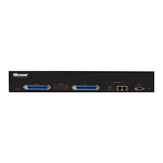
2. Hardware Installation The 24 ports VDSL MANAGED SWITCH has embedded Splitter between every VDSL side and POTS side. It permits you can deliver broadband service on the same lines as Plain Old Telephone Service (POTS), ISDN traffic and VDSL Signal. Several LED indicators for monitoring the device itself, and the network status. - Page 7 Connectors Connectors Description Type Connecting to the VDSL Modem via a RJ-21 VDSL LINE (1~24) RJ-21 cable Connecting to the telephone, Fax or ISDN POTS/ISDN (1~24) RJ-21 modem Gigabit Ethernet Connecting to an Ethernet network device RJ-45 RESET Restarts the switch LED definition For definitions of LED indicators, please refer to the following table: Status...
-
Page 8: Hardware Installation
2.1 Hardware Installation This chapter describes how to install the 24-ports VDSL managed switch to establish network connection. You may install the managed switch on any level surface (table, shelf, 19 inch rack or wall mounting). However, please take note of the following minimum site requirements before you begin. Pre-installation Requirements Before you start actual hardware installation, make sure you can provide the right operating environment, including power requirements, sufficient physical... - Page 9 Connect a RJ-45 Ethernet cable from a network switch to an available Ethernet port on SP3524A. The network switch should provide 10/100/1000 Mbps Giga Ethernet ports that are connected with SP3524A and uplink port for a network connection. Step 2: Connecting to RJ-21 VDSL LINE port for VDSL Modem (SP3501AS) connections.
- Page 10 Please ensure suitable VDSL Modem (SP3501AS) is installed before making a connection to any of the SP3524A VDSL LINE (1-24) station ports. Networking devices can be installed on a single telephone wire that can span up to maximum of 1.7km between the two points.
-
Page 11: Administration
3. Administration 3.1 In-Band Management Console Port (RS-232) Configuration (Change IP Address via Hyper- Terminal) Connect managed switch with PC/Laptop’s RS-232 port, using “Hyper- Terminal” in the Windows™ system. Set “Bits per second” at 9600 to the content window. Set “Flow control” at None After login window show on the screen, it will ask for Login Name and Password. - Page 12 Operation: Arrow/Tab/Backspace = Move light bar to select Item Enter = Select Item 1. Set IP Address: (1) Select “Switch Static Configuration” to enter the Switch Configuration page. (2) Select “Administration Configuration” to enter the Device Configuration page...
- Page 13 (3) Select “IP Configuration” to enter the IP configuration page (4) In the “IP Configuration”, it allows user to setup the DHCP, IP Address, Subnet Mask and Gateway. a. Select <Edit> to Change IP address, Subnet Mask and Gateway b. Select <Save> to save the configuration and go back to System...
- Page 14 Configuration page c. Select <Quit> to go back to the previous menu d. Use CTRL+A to go back to the last action...
-
Page 15: Remote Network Management
3.2 Remote Network Management IP Setting It must assign an IP for the MANAGED SWITCH via the console port (RS- 232 Port) before users configure the VDSL MANAGED SWITCH via Telnet and Web. Or users can modify the PC/Laptop’s IP domain same as the VDSL MANAGED SWITCH and use the manufacturer default IP to configure the VDSL MANAGED SWITCH. - Page 16 2. Remote control by “Web” The configuration of the switch can be performed using the following steps: Step1: Click the Start button followed by Control Panel. In the Control Panel, double-click the Network Connections. In the Network Connections window, double-click Local Area Connection.
- Page 17 Step 2: • Click Internet Protocol (TCP/IP) from the components list and then click the Properties Step 3: In the Internet Protocol (TCP/IP) Properties window, click the Use the following IP address.
- Page 18 Enter the following information: IP Address: 192.168.16.xxx ( xxx = 2~254) Subnet Mask: 255.255.255.0 Note: Do not use 192.168.16.250 as this address is reserved for the web management tool. Step 4: Open an Internet browser and enter http://192.168.16.250 in the address bar. Step 5: •...
- Page 19 Step1: Step: • Login in with User Username:admin Password :123 • Click OK button to enter the Configuration Menu.
-
Page 20: Web Management
4. Web Management 4.1. Port Status This page can see every port status that depended on user setting and the negotiation result. 1. State: Display port statuses disable or enable. “Unlink” will be treated as “off”. 2. Link: Down is “No Link”, UP is “Link”. 3. -
Page 21: Port Statistics
4.2. Port Statistics The following information provides a view of the current status of the unit. Press “Reset” button to clean all counts. -
Page 22: Tftp Update
4.3. TFTP Update The following menu functions allow user update the firmware and remote boot device: Install TFTP Turbo98 and execution. Copy firmware update version image.bin to TFTP Turbo98 directory. In web management select administrator—TFTP update firmware. Download new image.bin file then in web management press <update firmware>. -
Page 23: Tftp Backup
4.4. TFTP Backup TFTP Restore Configuration Use this function to set TFTP server address. User can restore EEPROM value from here, but before the MANAGED SWITCH restore the flash image file, the image file must store in TFTP server. TFTP Backup Configuration Use this function to set TFTP server IP address. -
Page 24: Ip Address
4.5. IP Address 1. User can configure the IP Settings and fill the new values in here. -
Page 25: Switch Settings
4.6. Switch Settings Basic Description: Display the name of device type. MAC Address: The unique hardware address assigned by manufacturer (default) Firmware Version: Display the device’s Firmware version. Hardware version: Display the device’s Hardware version. Default config value version: Display write to default EEPROM value table version. - Page 26 Priority Queue Service settings First Come First Service: The sequence of packets sent is depend on arrive order. All High before Low: The high priority packets sent before low priority packets. WRR: Weighted Round Robin. Select the preference given to packets in the switch's high-priority queue.
- Page 27 QoS Policy: High Priority Levels: 0~7 priority level can map to high or low queue. Collisions Retry Forever: Enable or Disable Collisions Retry Forever. Hash Algorithm: Select in CRC-Hash mode or Direct Map mode 802.1x Protocol: Enable or disable 802.1x Protocol.
-
Page 28: Port Controls
4.7. Port Controls This section shows you how to change every port status and speed mode. State: User can disable or enable this port control. Negotiation: User can set auto negotiation mode is Auto, Force of per port, Nway (specify the speed/duplex on this port and enable auto-negotiation). -
Page 29: Trunking
4.8. Trunking The Link Aggregation Control Protocol (LACP) provides a standardized means for exchanging information between Partner Systems on a link to allow their Link Aggregation Control instances to reach agreement on the identity of the Link Aggregation Group to which the link belongs, move the link to that Link Aggregation Group, and enable its transmission and reception functions in an orderly manner. - Page 30 group is local static trunking group. All ports support LACP dynamic trunking group. If connecting to the device that also supports LACP, the LACP dynamic trunking group will be created automatically. Work ports: Allow max four ports can be aggregated at the same time. If LACP static trunking group, the exceed ports is standby and able to aggregate if work ports fail.
- Page 31 State Activity Active (select): The port automatically sends LACP protocol packets. Passive (no select): The port does not automatically sends LACP protocol packets, and responds only if it receives LACP protocol packets from the opposite device. 1. A link having either two active LACP ports or one active port can perform dynamic LACP trunking.
-
Page 32: Filter Database
4.9. Filter Database IGMP Snooping The 24 ports VDSL MANAGED SWITCH supports IP multicast, you can enable IGMP protocol on web management’s switch setting advanced page, then display the IGMP snooping information in this page, you can view difference multicast group, VID and member port in here, IP multicast addresses range from 224.0.0.0 through 239.255.255.255. - Page 33 A message sent by a host to the carrier to indicate that Report the host wants to be or is a member of a given group indicated in the report message. A message sent by a host to the carrier to indicate that Leave the host has quit to be a m ember of a specific Group...
- Page 34 In the MAC Address box, enter the MAC address that wants to filter. 2. If tag-based (802.1Q) VLAN are set up on the switch, in the VLAN ID box, type the VID to associate with the MAC address. Click the Add. Choose the MAC address that you want to delete and then click the Delete.
-
Page 35: Vlan Config
4.10. Vlan Config A Virtual LAN (VLAN) is a logical network grouping that limits the broadcast domain. It allows you to isolate network traffic so only members of the VLAN receive traffic from the same VLAN members. Basically, creating a VLAN from a switch is logically equivalent of reconnecting a group of network devices to another Layer 2 switch. - Page 37 1. Click Add to create a new VLAN group. 2. Enter the VLAN name, group ID and select the members for the new VLAN, then click Apply. 3. If the VLAN groups over the page’s limitation, user can use “Next Page” to view other VLAN groups.
- Page 38 802.1Q VLAN This page, user can create Tag-based VLAN, and enable or disable GVRP protocol. There are 256 VLAN groups to provide configure. Enable 802.1Q VLAN, the all ports on the switch belong to default VLAN, VID is 1. The default VLAN can’t be deleted.
- Page 39 GVRP (GARP [Generic Attribute Registration Protocol] VLAN Registration Protocol) GVRP allows automatic VLAN configuration between the switch and nodes. If the 24 ports VDSL MANAGED SWITCH is connected to a device with GVRP enabled, you can send a GVRP request using the VID of a VLAN defined on the 24 ports VDSL MANAGED SWITCH, the 24 ports VDSL MANAGED SWITCH will automatically add that device to the existing VLAN.
- Page 40 The 24-ports VDSL MANAGED SWITCH has 16 PVID ranges. PVID of Port 1 ~ Port 26 must be in the same range. Num. PVID Range Num. PVID Range Num. PVID Range Num. PVID Range 1~255 1024~1279 2048~2303 3072~3327 256~511 1280~1535 2304~2559 3328~3583 512~767...
- Page 41 VDSL MANAGED SWITCH has two ingress filtering rule as follows: Ingress Filtering Rule 1: Forward only packets with VID matching this port's configured VID. Ingress Filtering Rule 2: Drop Untagged Frame.
-
Page 42: Spanning Tree
4.11. Spanning Tree The Spanning-Tree Protocol (STP) is a standardized method (IEEE 802.1D) for avoiding loops in switched networks. When STP enabled, to ensure that only one path at a time is active between any two nodes on the network. You can enable Spanning-Tree Protocol on web management’s switch setting advanced item, select enable Spanning-Tree protocol. - Page 43 You can set new value for STP parameter Parameter Description You can change priority value, A value used to identify the root Priority bridge. The bridge with the lowest value has the highest priority and is selected as the root. Enter a number 1 through 65535. You can change Max Age value, The number of seconds a bridge waits without receiving Spanning-Tree Protocol configuration Max Age...
- Page 44 Parameter Description Define the priority of each port, the rage is from 0 to 255, the lower Port Priority number has the higher priority. Default Value is 128. Specifies the Path Cost of the port that switch uses to determine which port are the forwarding ports the lowest number is forwarding Path Cost ports, the rage is from 1 to 65535 and default value base on...
-
Page 45: Port Sniffer
4.12. Port Sniffer The Port Sniffer is a method for monitor traffic in switched networks. Traffic through ports can be monitored by one specific port. That is, traffic goes in or out monitored ports will be duplicated into sniffer port. Sniffer Mode: Press... -
Page 47: Snmp
4.13. SNMP Any Network Management running the simple Network Management Protocol (SNMP) can manage the switch, provided the Management Information Base (MIB) is installed correctly on the management station. The SNMP is a Protocol that governs the transfer of information between management and agent. - Page 48 2. Community strings serve as passwords and can be entered as one of the following: RO: Read only. Enables requests accompanied by this string to display MIB-object information. RW: Read write. Enables requests accompanied by this string to display MIB-object information and to set MIB objects. 3.
-
Page 49: Security Manager
4.14. Security Manager Using this page, user can change web management user name and password. User name: Type the new user name. Password: Type the new password. Reconfirm password: Retype the new password. Click Apply. -
Page 50: 802.1X Config
4.15. 802.1X Config System Configuration 802.1x makes using of the physical access characteristics of IEEE802 LAN infrastructures in order to provide a means of authenticating and authorizing devices attached to a LAN port that has point-to-point connection characteristics, and of preventing access to that port in cases in which the authentication and authorization process fails. - Page 51 exchanges between the supplicant and authentication server (Default value is 30 seconds). • Server Timeout: used to determine timeout conditions in the exchanges between the authenticator and authentication server (Default value is 30 seconds). • ReAuthMax: used to determine the number of re-authentication attempts that are permitted before the specific port becomes unauthorized (Default value is 2 times).
-
Page 52: Modem Location
4.16. Modem Location This function allows for the identification of the location of each Remote Modem. In the text box to a port, type the location of the Remote Modem for that port. The field is limited to alphanumeric characters and hyphen, and will accept a maximum 10 characters. -
Page 53: Interleave
4.17. Interleave This function is used in digital data transmission technology to protect the transmission against noise issue and data error. If during transit more than a certain amount of data has been lost then the data cannot be correctly decoded. Short bursts of noise on the line can cause these data packets to become corrupt and the modem has to re- request data which in turn can slow down the overall rate at which data is transmitted. - Page 54 The diagram below is an example of how interleaved traffic is transmitted. If your line is particularly susceptible to bursts of noise then interleaving should improve your vdsl experience simply because if you lose a whole batch of data then this could cause your modem to loose sync with the exchange.
- Page 55 The following ports can modify the desired interleave depth. The current information provides a view of the current status of the unit.
-
Page 56: Reset System
4.18. Reset System Reset 24 ports VDSL MANAGED SWITCH to default configuration. -
Page 57: Reboot
4.19. Reboot Reboot the 24 ports VDSL MANAGED SWITCH in software reset. -
Page 58: Applications
5. Applications The VDSL provides home network architecture. Transforming an apartment into a Multiple-Family Home network area, sharing a single internet account for multiple users with Router & Cable Modem, it can provide unlimited access time in the internet at a reasonable low price. Bridging Functions The 24 ports VDSL MANAGED SWITCH provides full transparent bridging function. - Page 59 The 24 ports VDSL MANAGED SWITCH provides a high speed, 5/15/25Mbps transmission over existing home telephone wiring over a single Internet account to provide simultaneous independent Internet access to multiple users. No mater ISDN Telephone system or POTS Telephone system you are. VDSL Technology let you can use telephone system and VDSL network system in the same time.
-
Page 60: Appendix A: Rj-21 Telco Ports Distribution
Appendix A: RJ-21 Telco ports distribution RJ-21 Pin and VDSL port contrast list VDSL 50 Pin RJ-21 Cable Connector List Cable Characteristic = 24 AWG twist wire 24 & 49 23 & 48 22 & 47 21 & 46 20 & 45 19 &... - Page 61 RJ-21 Cable Drawing (150 cm Male to Male)
-
Page 62: Appendix B: Vdsl Spectrum
Appendix B: VDSL Spectrum VDSL Technology – Requirements & Definitions Spectral Allocation • Co-exists with legacy Voice and ISDN services • Co-exists with other xDSL technologies Slide 5 • Programmable notch filter to avoid Radio Frequency Interference 06-April-2000 page: 5 ©... -
Page 63: Appendix C: Product Specification
Appendix C: Product Specification IEEE802.3, 10BASE-T IEEE802.3u, 100BASE-TX IEEE802.3ab, 1000BASE-T IEEE802.3x, Flow control IEEE 802.1v Protocol-based VLAN Standards IEEE802.1q, Tag-based VLAN IEEE802.1p, Traffic prioritization (CoS) IEEE802.1d, Spanning Tree Protocol IEEE802.3ad LACP IEEE802.1x network access control 2 * RJ-45 10/100/1000Mbps Ethernet port Interface 1 * RJ-21 connector for VDSL LINE connection 1 * RJ-21 connector for POTS/ISDN connection... - Page 64 Bandwidth management (100Kbps to 5M/15M/25Mbps) Switching Features IEEE 802.1q/p Tag-based VLAN IEEE 802.1v Protocol-based VLAN IEEE802.3ad LACP IEEE 802.1d Spanning tree IGMPv2 MAC/IP filtering Port Mirror Broadcast Storm Control Long packet size up to 1536 bytes Power and POST LED Indictor Link/Active/Speed/Duplex Status for Ethernet port Link for VDSL LINE port Transmitter: 900 kHz ~ 3.9MHz...
-
Page 65: Appendix D: Example Of Vlan Setting
Appendix D: Example of VLAN Setting Example 1: 4 users join to Internet by VDSL system like following drawing, and have 7 demands. User A connects to port 1 and join to Internet through port 26 User B connects to port 2 and join to Internet through port 26 User C connects to port 3 and join to Internet through port 26 User D connects to port 4 and join to Internet through port 26 User A isolate with Users B, C and D... - Page 66 Setup VLAN Name=UserA, VID=21, select member ports 1 & 26 Select Untag or Tag Setup. Unless the device (computer or switch) which connect to port 1 or port 26 can support Tagging VLAN, otherwise select Untag.
- Page 67 Add a VLAN Group Name=UserB, VID=22 member ports = port 2 & port 26 Add a VLAN Group Name=UserCD, VID=23 member ports = port 3, port 4 & port 26...
- Page 68 Example 2: 4 users join to Internet through 2 IP DSLAMs like the following drawing, and have 7 demands. User A connect to port 1 of VDSL-1 and join to Internet through port 26 of VDSL-2 User B connect to port 2 of VDSL-1 and join to Internet through port 26 of VDSL-2 User C connect to port 1 of VDSL-2 and join to Internet through port 26 of VDSL-2 User D connect to port 2 of VDSL-2 and join to Internet through port 26 of VDSL-2 User A isolate with Users B, C and D...
- Page 69 Port Number Untag/Tag Select Untag Add a VLAN Group, Group name=UserBD VID=12, member ports = port 2 & port 26 Select Untag or Tag Setup for VID=12 group: Port Number Untag/Tag Select Untag VDSL-2 SETUP: a. Setup Port VID: Port 1 PVID=21, Port 2 PVID=12 b.
- Page 70 Add a VLAN Group, Group name=UserC VID=21 member ports = port 1 & port 26 Select Untag or Tag Setup for VID=21 group: Port Number Untag/Tag Select Untag Untag...
-
Page 71: Appendix E: Troubleshooting
Appendix E: Troubleshooting Nosing VDSL indicators The VDSL can be easily monitored through its comprehensive panel indicators. These indicators assist the network manager in identifying problems of the IP DSLAM may encounter. This section describes common problems you may encounter and possible solutions. 1. -
Page 72: System Diagnostics
3.3 Please check the correct Dip Switch setting. Note: Phone cable must meet CAT 3 standard or above and without clustering, otherwise will cause more cross talk issue to reduce DSL power driver. System Diagnostics Power and Cooling Problems If the POWER indicator does not turn on when the power cord is plugged in, you may have a problem with the power outlet, power cord, or internal power supply as explained in the previous section. - Page 73 The best way to resolve this problem is to upgrade these devices to version that will support auto-negotiation. Cabling 1. Verify that the cable type is correct. Be sure RJ-45 cable connectors are securely seated in the required ports. Use 100Ω straight-through cables for all standard connections.
-
Page 74: Appendix F: Compliance And Safety Information
Appendix F: Compliance and Safety Information FCC Radio Frequency Interference Statement This equipment has been tested and found to comply with the limits for a computing device, pursuant to Part 15 of FCC rules. These limits are designed to provide reasonable protection against harmful interference when the equipment is operated in a commercial environment. - Page 75 Important Safety Instructions Caution: The direct plug-in wall transformer serves as the main disconnect for the product. The socket outlet shall be installed near the product and be readily accessible. Caution: Use only the power supply included with this product. In the event the power supply is lost or damaged: In the United States, use only with CSA certified or UL listed Class 2 power supply, rated 5Vdc 1A or above.
- Page 76 Warranty The original owner that the product delivered in this package will be free from defects in material and workmanship for one year parts after purchase. There will be a minimal charge to replace consumable components, such as fuses, power transformers, and mechanical cooling devices. The warranty will not apply to any products which have been subjected to any misuse, neglect or accidental damage, or which contain defects which are in any way attributable to improper installation or to alteration or repairs made or performed by any...
Need help?
Do you have a question about the SP3524A and is the answer not in the manual?
Questions and answers