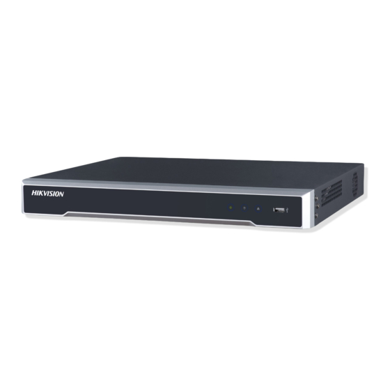
Do you have a question about the DS-7604 and is the answer not in the manual?
Questions and answers
Александр
January 20, 2025
Забыл.пароль
1 comments:
Mr. Anderson
February 4, 2025
1. Navigate to the Admin Password text box. 2. Type the current admin password (default is 12345). 3. Check the "New Admin Password" checkbox. 4. Enter the new password and confirm it in the provided text boxes. 5. Click "Next" to save the changes.
HIKVision DS-7604, DS-7608, DS-7616 Analogue CCTV Recorder USER MANUAL DS-7600 Series DVR USER MANUAL Version 1.2.0 www.cctvireland.ie shop@cctvireland.ie...
Page 2
The content of this manual is furnished for informational use only, is subject to change without notice, and should not be construed as a commitment by Hikvision Digital Technology Co., Ltd. (Hikvision). Hikvision assumes no responsibility or liability for any errors or inaccuracies that may appear in the book.
Regulatory Information FCC Information This equipment has been tested and found to comply with the limits for a digital device, compliance: pursuant to part 15 of the FCC Rules. These limits are designed to provide reasonable protection against harmful interference when the equipment is operated in a commercial environment. This equipment generates, uses, and can radiate radio frequency energy and, if not installed and used in accordance with the instruction manual, may cause harmful interference to radio communications.
Page 4
Safety Warnings and Cautions Please pay attention to the following warnings and cautions: Hazardous Voltage may be present: Special measures and precautions must be taken when using this device. Some potentials (voltages) on the device may present a hazard to the user. This device should only be used by the Employees from our company with knowledge and training in working with these types of devices that contain live circuits.
Page 5
Power Cord Requirements: The connector that plugs into the wall outlet must be a grounding-type male plug designed for use in your region. It must have certification marks showing certification by an agency in your region. The connector that plugs into the AC receptacle on the power supply must be an IEC 320, sheet C13, female connector.
Page 6
Thank you for purchasing our product. If there is any question or request, please do not hesitate to contact dealer. This manual is applicable to DS-7604HI-S, DS-7604NI-S, DS-7604NI-S/M and DS-7608NI-S series DVR. This manual may contain several technically incorrect places or printing errors, and the content is subject to change without notice.
Preventive and Cautionary Tips Before connecting and operating your DVR, please be advised of the following tips: • Ensure unit is installed in a well-ventilated, dust-free environment. • Unit is designed for indoor use only. • Keep all liquids away from the DVR. •...
TABLE OF CONTENTS C H A P T E R 1 ..............................6 Introduction ................................6 Overview ................................7 Product Features............................... 7 Product Application Diagram .......................... 9 Operating Your DVR ............................9 Using the Front Panel Controls ........................ 9 IR Remote Control ..........................11 Using a USB Mouse ..........................
Page 9
View System Information ..........................90 View System Log ............................91 C H A P T E R 1 3 ..............................93 Appendix ................................93 Glossary ................................94 FAQ ..................................95 List of Hikvision IP Cameras Supported by DS-7600 NVR ................96 www.cctvireland.ie shop@cctvireland.ie...
Local Monitoring DS-7604HI-S supports 1/4/9-division video live view, with adjustable cameras order for display. DS-7604 NI-S and DS-7604NI-S/M support 1/4-division video live view. DS-7608 NI-S support 1/4/9-division video live view. Group switch, manual switch and automatic cycle modes selectable for video live view, with the auto cycle period configurable.
Page 12
HDD file system is compatible with Windows. Use pre-allocating hard disk management technology, and no disk fragments. Record & Playback Cycle and non-cycle recording mode. Supports normal and event video encoding parameters. Multiple recording types, including manual, continuous, alarm, motion, motion | alarm and motion & alarm recording, etc.
IR (Infrared) Remote, a Mouse and the Soft Keyboard. Using the Front Panel Controls Your DVR comes with built-in front panel controls, as shown in the following figure: Figure4. DS-7604 Series DVR Front Panel The controls on the front panel include: 1. Status Indicators: •...
Page 14
through tab pages. It will also bring up the Channel & OSD Position settings. • 4GHI/ESC: (1) Enter numeral “4”; (2) Enter letters “GHI” (3) Exit and back to the previous menu • 5JKL/EDIT: (1) Enter numeral “5”; (2) Enter letters “JKL”; (3) Delete characters before cursor;...
• 7PQRS/REC: (1) Enter numeral “7”; (2) Enter letters “PQRS”; (3) Manual record, for direct access to manual record interface; manually enable/disable record. • 8TUV/PTZ: (1) Enter numeral “8”; (2) Enter letters “TUV”; (3) Access PTZ control interface. • 9WXYZ/PREV: (1) Enter numeral “9”; (2) Enter letters “WXYZ”; (3) Multi-camera display in live view.
EDIT: Same as JKL/EDIT button on front panel. A: Same as A/FOCUS+ button on front panel. REC: Same as REC/SHOT button on front panel. PLAY: Same as MNO/PLAY button on front panel. INFO: Same as ZOOM+ button on front panel. VOIP: Same as MAIN/SPOT/ZOOM- button on front panel.
shown in Figure 7. Figure7. Soft Keypad The buttons on the soft keyboard represents: Lowercase: Designates lowercase input is being used. Uppercase: Designates uppercase input is being used. Switch to Lowercase: Switch to lowercase input. Switch to Uppercase: Switch to uppercase input. Number: Designates number input is being used.
Page 18
DB15 connector for VGA output. Display local video output and menu RS-485 Interface Connector for RS-485 devices. T+, T- pin connects to PTZ ALARM IN Connector for alarm input (up to 4 alarm inputs) ALARM OUT Connector for alarm output (1 alarm output) POWER Switch for turn on/off the device 12VDC power supply...
Page 19
Figure11. Rear Pane of DS-7604NI-S/M Item Description USB Interface Connector for USB devices VIDEO OUT BNC connector for video output AUDIO IN RCA connectors for analog audio input AUDIO OUT RCA connector for audio output Connector for LAN (Local Area Network) RS-485 Interface Connector for RS-485 devices.
Starting and Shutting Down Your DVR Proper startup and shutdown procedures are crucial to expand the life of your DVR. To start your DVR: Please make sure the input voltage meets the requirements of DVR, and the GND is in grounding. For DS-7604HI-S, DS-7604NI-S DVR and DS-7608NI-S, please make sure the VGA port on its rear panel has connected with a display device or the VIDEO OUT port has connected to a monitor, or else no prompt message will be displayed on screen after device startup and the menu operation is inaccessible as well.
Page 22
Figure2. Setup Wizard To start menu operation by using the Setup Wizard: Click the Next button on the Wizard window. This will take you to the User Permission window, shown in Figure 3. Figure3. User Permission Navigate to the Admin Password text box. Type the admin password into the Admin Password text box.
Page 23
input password whenever you enter the menu, you can disable password. Enter the correct date and time under System Time. Click the Apply button to save the setting. Select the DST Settings tab to enable DST, and More Settings to change device name and number, shown in Figure5.
Page 24
Figure8. Schedule Settings 18. Click Edit button to enter a new recording schedule, shown in Figure 9. 19. Check both the Enable Schedule and All Day checkbox. This will enable the recording schedule and make it record continuously all day. Figure9.
After completion of Setup Wizard, enter the Live View window. Setting Date & Time It is extremely important to setup the system date and time to accurately timestamp recordings and events. To setup date and time: Open the Menu window by clicking the MENU button on the remote or front panel. You can also go to the Menu window by right clicking with the mouse and clicking the Menu button.
Live View On-screen Display The Live View mode is automatically started after the DVR boots up. It is also at the very top of the menu hierarchy, thus hitting the ESC multiple times (depending on which menu you’re on) will bring you to the Live View mode.
• PTZ: Enter PTZ Control mode of the selected camera. • Digital Zoom: Enter Digital Zoom interface of the selected camera. • Menu: Enter Main menu. • Start Auto-switch: Enable multi-camera sequence in Live View mode. Note: The dwell time of the live view configuration should be set before using Start Auto-switch function. Figure2.
Figure4. Display Settings Configure the following settings for Live View Display: • Video Output: Set the video output modes, including Main Vout and Auxiliary Vout. • Mode: Set the live view display mode to be 1*1, 2*2 or 3*3. • Dwell Time: Set the dwell time for camera switching when Start Auto-switch is selected in Live View.
Page 30
Figure5. Camera Order Settings Operate the following steps to set camera order: Enter the Display Settings menu (Menu > Settings > Display) and click Set in the Camera Order item. Select the video output port and the display mode (1*1, 2*2 and 3*3 modes selectable). Note: DS-7604NI-S/M and DS-7608NI-S model only provide the Main Vout.
Configure Record Settings There are multiple ways to setup your DVR recording. They include setting up a recording schedule, triggering a recording by motion detection and/or a sensor alarm, and manually starting the recording. Before Record Settings Before configuration, please make sure your DVR has been installed with HDD and has completed its initialization, otherwise, access Menu >...
Figure2. More Record Settings • Pre-Record: Set the time in seconds to pre-record before the actual recording begins. • Post-Record: Set the time in seconds to post-record after the actual recording has ended. • Recording Expired Time: Set the expiration time in days for recorded video. Record files after expiration time will be deleted.
Figure4. Scheduling a Recording Select Camera you want to configure recording schedule. Click the Edit button to enter the Schedule Settings dialog box. Click and check Enable Schedule checkbox. Select the day you want to set up the schedule or select All Week to record for entire week. Click All Day to enable recording for entire day, or select different periods for each day.
Protect Recorded Files Two methods are provided to prevent recorded files from being deleted from the HDD or overwritten during cycle recording: set the recorded files to be locked or set the HDD that the files reside on to be read-only. Lock/Unlock Recorded Files To lock or unlock a recorded file: Click Menu >...
Click Menu > HDD to access the HDD Management dialog box, shown in Figure 8. Figure8. HDD Management Menu Select the General tab. Select the HDD to set to read-only. Click the Set button. This will take you to the HDD Settings menu, shown in Figure 9. Figure9.
Page 37
Select the HDD to be used for redundancy, as shown in Figure 10. Figure10. HDD Management Menu Click the Set button. This will take you to the HDD Settings menu. Set HDD Status to Redundancy, shown in Figure 11. Verify at least one other HDD is set to R/W (read/write).
Page 38
Figure12. Additional Record Settings Set Redundantly Record to Yes. Click OK to save settings. Repeat steps 8-12 for other cameras you want to set redundant recording. www.cctvireland.ie shop@cctvireland.ie...
Video Playback The Client application allows all users to play back record files of the specified period. Multi-camera simultaneous playback is supported. Playback Interface Multiple toolbar and buttons are provided on the playback interface to control the video playback. Refer to the following figure: Figure1.
Enter the Video Search menu by clicking Menu > Video Search. Set the search parameters by selecting cameras to search, video/file type and the start/end time (as shown in Figure 3). Note: DS-7604NI-S/M, DS-7604NI-S and DS-7608NI-S models provide no analog camera connection.
Page 42
Figure5. Video Event Search Menu Click the Search button to start bring up the list of search results. After search results are presented, you can press play icon to playback the selected event, show in figure 7. Figure6. File Selection Menu Recordings will automatically be play backed in the Playback interface, shown in Figure 7.
Playback in Live View Mode The Client application also allows you to play back record files in Live View mode. To play back by channel in Live View mode: • By Using a Mouse: Right-click the mouse on desired channel and select the Playback option. Record video from the selected channel will start playing back in the Playback window.
Figure9. Log Search Menu 2. Set Major Type to Information; set Minor Type to Start Record or End Record; and then select Start Time and End Time as well. Click the Search button. 3. Click the Search button. A list of search results will be displayed. Select the video log to play back and click Play.
Back Up Recorded Files Recorded files can be backed up to various devices, such as USB flash drives, USB HDDs or a DVD writer. Exporting Files To export recorded files via Video Search: Enter the Video Search menu (shown in Figure 1) by clicking Menu > Video Search. Figure1.
Page 47
Figure 3. Export Menu 6. Select device to export to from drop-down list (USB Flash Drive, USB HDD, DVD Writer). If backup device is not recognized: • Click the Refresh button. • Reconnect device. • Check for compatibility from vendor. Click Start to begin backup process, shown in Figure 4.
Note: Video Player software will automatically be copied on to the device that the recorded files were exported To export recorded files via Event Search: Enter the Event Search menu (shown in Figure 6) by clicking Menu > Event Search Figure6.
• By Using the Mouse: Enter the Playback interface (See Video Playback). Click the Clip Start/Stop button on the Playback Control Panel, and select the start and end of the video clip during playback. Repeat for additional clips. Click the Quit Playback button to exit from the Playback interface. You’ll then be prompted to save the clips, as shown in Figure 6.
Configure Alarms Motion Detection Alarm Operate the following steps to configure Motion Detection Recording: Enter Camera Setting: Click Menu > Settings > Camera to access the Camera Management dialog box, as shown in Figure 1. Select the channel to configure motion detection and click Set. Note: DS-7604NI-S/M, DS-7604NI-S and DS-7608NI-S models provide no analog camera connection, please select IP camera for configuration.
Page 52
Figure3. Motion Detection Area Right click mouse or press the MENU button on the front panel to set the Motion Detection Sensitivity, shown in Figure 4. Higher sensitivity value corresponds to higher sensitivity level. Figure4. Motion Sensitivity Setting Click OK to return to the Advanced Camera Settings menu. Click the Handle button to enter the Exception Handle menu, shown in Figure 5.
Click OK to complete motion settings for the selected camera. You may now add a schedule to start recording when motion is detected (See Scheduling a Recording). Setting up Sensor Alarms Recordings can also be triggered from an external relay alarm device. To set up sensor alarms: Click Menu >...
Page 54
Figure8. Triggered Cameras Menu Click the OK button to complete setup. You may now add a schedule to start recording when an alarm is triggered (See Scheduling a Recording). Alarm outputs may also be configured in the Alarm Management menu. To set up Alarm Output: Select the Alarm Output tab.
Configure the settings for selected output. Select OK to save and exit. Note: If the Hold For option is selected as Manually Stop, the alarm will only stop when you manually stop it (See Triggering Alarm Outputs Manually). Note: Triggering an IP camera will require the necessary permissions from the camera. Triggering Alarm Outputs Manually You may also trigger alarm outputs manually through the Manual Alarm menu.
Page 56
Figure12. Camera Management Menu Select camera under Channel No. to configure video loss detection for and click the Set button. Select the Advanced tab. Check the Video Loss Detection checkbox to enable this feature, as shown in Figure 13. Figure13. Camera Settings Menu Click the Handle button to enter the Exception Handle menu, shown in Figure 14.
Select the Schedule tab. Set the schedule when you want video loss detection to be enabled. Schedule can be set for all week or any day of the week with up to 8 time periods per day. Click Apply to finish the settings. Repeat above steps to configure settings for other channels.
Figure17. Tampering Area Setting Set detection sensitivity. The higher the value set, the higher the sensitivity. Click OK to return to the Camera Settings/Management menu. Click the Handle button to enter the Exception Handle menu, shown in Figure 18. Select the Handle tab to configure exceptions handling. Exception trigger options will be described in the next section (See Understanding Exception Trigger Options).
To set exceptions: Click Menu > Settings> Exception to enter the Exception menu. Select the exception to configure under Exception Type. Select triggering options, as shown in Figure 19. Trigger options are further explained in the next section (See Understanding Exception Trigger Options). Figure19.
Configuring Network Settings Network settings must be configured if DVR is used for monitoring over network. Configuring General Settings To configure general network settings: Click Menu > Settings > Network to enter the Network Settings menu, shown in Figure 1. Figure1.
PPPoE Settings Your DVR also allows for Point-to-Point Protocol over Ethernet (PPPoE) access. To set up PPPoE access: Click Menu > Settings > Network to enter the Network Settings menu. Select the General tab, as shown in Figure 3. Figure3. Network Settings Menu Select the Advanced tab to enter the Advanced Network Settings menu, shown in Figure 4.
Figure5. PPPoE Settings Check the PPPoE checkbox to enable this feature. Enter User Name, Password, and Confirm Password for PPPoE access. PPPoE credentials can be obtained from your network administrator. Once the setup is completed, your DVR will automatically dial-up into your network after reboot. Click OK to save settings and exit Network Settings menu.
DVR Domain Name, enter the domain obtained from the DynDNS web site. Finally, enter the User Name and Password registered in the DynDNS network. Figure7. DynDNS Settings NTP Server Settings A Network Time Protocol (NTP) Server may also be set up on your DVR to maintain accurate current date and time.
Remote Alarm Host Settings With a remote alarm host set, the DVR will send a signal to the host when an alarm is triggered. The remote alarm host must have the Network Video Surveillance software installed. To set up a remote alarm host: Enter Network settings menu by clicking Menu >...
Figure10. Host/Others Menu Click OK to save settings and exit the Host/Others menu. Configuring Server and HTTP Ports If you would like to change the server and HTTP ports from the default settings, you can do so in the Network Settings menu.
Navigate PTZ Menu PTZ menus can be navigated through with either the mouse or the front panel/remote. For quick access to certain PTZ settings, right clicking with the mouse in the display while in PTZ control mode will enter the PTZ settings menu.
Figure2. PTZ Settings Menu Select channel where PTZ camera is installed next to Camera label. Configure the settings of baud rate, date bit, stop bit, parity, flow control, PTZ protocol and address. Click OK to save settings and exit the PTZ Settings menu. Note: All setting parameters (baud rate, date bit, stop bit, parity, flow control, PTZ protocol and address) must be consistent with the PTZ camera connected.
Light: Turns PTZ light (if applicable) on and off. Wiper: Turns PTZ wiper (if applicable) on and off. Zoom In: Instantly zooms PTZ in. Center: Centers PTZ. Customizing Presets Presets can be set to move your PTZ camera to a desired preset location. To set up and call custom PTZ presets: Enter the PTZ Control interface, shown in Figure 3, by selecting PTZ from the mouse menu or clicking the PTZ button on the front panel.
Page 71
Figure5. Patrol Management Menu In the Patrol Management menu, you may: • Configure Patrol: Select a Patrol Number to set. Select valid presets (See Customize Presets) and click the Set button to enter the Patrol configuration menu. A sequence should have at least 2 valid presets. Set the Key Point No., Duration, and Speed (Figure 6).
Figure7. Patrol Management Menu Customize Patterns Patterns can be setup by recording the movement of the PTZ. To set up and call PTZ patterns: Enter the PTZ Control interface, shown in Figure 3, by selecting PTZ from the mouse menu or clicking the PTZ button on the front panel.
Note: Each IP camera is allowable to be connected to a single DS-7604 unit so as to avoid confused control. Before configuring IP cameras, please ensure that all IP cameras are connected to the same network as your DVR and the network settings for your DVR is properly set up (See Configuring Network Settings).
Page 75
Figure2. Camera Enabled Status Menu b) Uncheck the checkbox to disable corresponding camera. Click OK to save settings. A confirmation message then will appear on the screen asking you to reboot the DVR. Click Yes to reboot the unit. After the system has rebooted, enter the Camera Management menu to continue with the following steps.
Figure4. Camera Management Menu Click OK to save settings and exit the Camera Management menu. To adjust record settings parameters of IP camera: Click Menu > Settings > Record to enter the Record Settings menu, shown in Figure 5. Figure5. Record Settings Menu Select the General tab.
connection; please select IP cameras for configuration. Configure desired OSD settings, as shown in Figure 6. Figure6. OSD Settings Menu Set up Privacy Mask You may setup privacy mask to mask off sensitive or private areas in the field of view of a camera. To setup privacy mask: Click Menu >...
Figure8. Setting Mask Area Select OK to save settings and exit the Mask Area Settings interface. Adjust Display Settings Display settings such as the brightness, contrast, saturation and hue can also be adjusted in the Camera Management menu. To adjust display settings: Click Menu >...
Manage HDDs Initializing HDDs A new installed hard disk drive (HDD) must be first initialize before it can be used with your DVR. Initializing the HDD will erase all data on it. To initialize a HDD: Click Menu > HDD to enter the HDD Management menu, shown in Figure 1. Figure1.
Page 81
Figure2. HDD Management Menu Click Add to enter Network HDD menu. Select type as NAS or IP SAN, shown in Figure 3 when selected as NAS. Figure3. Network HDD Menu Select Add button to add network HDD to HDD list. Figure4.
Set HDD Groups Your DVR can separate multiple HDDs into groups. Videos from specified channels can be set to be recorded onto a particular HDD group. To set up a HDD group: Click Menu > HDD to enter the HDD Management menu. Select HDDs to be added to group.
Figure6. HDD Settings Menu Set HDD Status to Read-Only. Select OK to save settings and exit the current menu. Note: Once set to read-only, the HDD cannot be written to until it is set back to read/write (R/W). If the HDD that is currently being written to is set to read-only, the data will be recorded to the next HDD.
Enter the HDD Management menu by clicking Menu >HDD, select Advance tab, shown in Figure 7. Figure7. S.M.A.R.T Function 2. The checkbox of Enable S.M.A.R.T is already checked in default. 3. Select a HDD you want to view S.M.A.R.T information, the corresponding information will be displayed below, shown in above figure.
Page 85
Figure9. Exception Menu Select HDD Error under Exception Type. Select trigger action. Trigger actions are further explained in Understanding Exception Trigger Options. www.cctvireland.ie shop@cctvireland.ie...
Configure System Settings Configuring General Settings General settings such as the system language can be configured in the General Settings menu of your DVR. To configure general settings: Click Menu > Settings > General to enter the General Settings menu, shown in Figure 1. Figure1.
Figure2. More Settings Menu Configure the following settings: • Device Name: Name of the DVR used. • Device No.: Device number of DVR. • CVBS Output Brightness: Video output brightness. • Transparency: Menu transparency. • Operation Timeout: Set timeout time for menu inactivity. For example, if timeout time was set to 5 minutes, after 5 minutes of inactivity in the General Settings menu, you’ll be returned to the Live View.
• Transparent Channel: Connect a serial device directly to the DVR. The serial device will be controlled remotely by the PC through the network and the protocol of the serial device. Note: DS-7604 Series DVR provides no RS-232 port, thus it is unallowable to set parameters control or create transparent channel. Managing User Accounts By default settings, your DVR is configured with the user name of admin and the password of 12345.
Page 90
• Operator: The Operator user level has the authority to configure two-way audio in network settings and all parameters in channel settings. • Guest: The Guest user can not configure network settings, but can configure the local playback as well as the remote playing in channel settings. If User’s MAC is configured and enabled, the user may only access the DVR from that particular MAC address.
• Two-way Audio: Ability to use two-way radio between the remote client and the DVR. • Remote Alarm Control: Remote alert or control the relay output of the DVR. Alarm and exception settings must be configured properly to upload to host. •...
Figure9. Modify User Menu Edit user information. To modify user permissions, click on the privileges button. Permissions settings are defined in the Adding a New User section described above. Click the OK button to exit menu. Manage System Importing & Exporting Configuration Configuration information from your DVR can be exported to a USB device and imported into another DVR.
Updating System Firmware The firmware on your DVR can be updated by using two methods. These methods include updating via an USB device or over the network via a FTP server. To update via an USB device: Connect USB device to DVR. The firmware file must be located in the root directory of your USB device.
Select Upgrade to begin update process. After the system firmware has been update, reboot the DVR. Note: If the DVR fails to update, please contact your system supplier for further assistance. Restore Default Settings To restore default factory settings to your DVR: Click Menu >...
View System Log Many events of your DVR are logged into the system log. To access the system logs and search for these events: Click Menu > Maintenance > Log Search to enter the Log Search menu, shown in Figure 15. Figure15.
Page 96
Figure17. Log Search Export Menu Click Cancel to exit the current menu. www.cctvireland.ie shop@cctvireland.ie...
Glossary • Dual Stream: Dual stream is a technology used to record high resolution video locally while transmitting a lower resolution stream over the network. The two streams are generated by the DVR, with the main stream having a maximum resolution of 4CIF and the sub-stream having a maximum resolution of CIF.
• Why does my DVR make a beeping sound after booting? There are a few reasons for the warning beep your DVR makes after booting. 1. There is no HDD present in the DVR. 2. The HDD has not been initialized. 3.
List of Hikvision IP Cameras Supported by DS-7600 NVR Main Stream Resolution Suppor Suppor Suppor IPC Sub Sub Stream Audio Supported Encoding Latest ted by ted by ted by Model Stream Resolution Compre Platform Type Resolution Format/Transmission/P Version DS-760 DS-760...
Page 101
1920*1080/2 560*1920/20 1080P/720P/256 Standard H.264+ V2.0 build DS-2CD886MF/BF-E Support 640*480 G.711 48*1536/128 0*1920 Standard RTSP+RTP 101102 0*720 DS-2DF1-601/2/3/4/5/ 6/7/8H(F) 4CIF/DCIF/2 SD IP DS-2DF1-611/2/3/4/5/ 4CIF/DCIF/2CIF HIK H.264+HIK V2.0.1 build Support CIF/CIF/QCI CIF/QCIF CIF/QCIF G.722 Dome 6/7/8H(F) /CIF/QCIF RTSP+PS 100513 DS-2DF1-631/2/3/4/5/ 6/7/8H(F) VGA/720P/X HIK H.264+HIK V2.0.1 build...
Need help?
Do you have a question about the DS-7604 and is the answer not in the manual?
Questions and answers
Забыл.пароль
1. Navigate to the Admin Password text box.
2. Type the current admin password (default is 12345).
3. Check the "New Admin Password" checkbox.
4. Enter the new password and confirm it in the provided text boxes.
5. Click "Next" to save the changes.
This answer is automatically generated