
Subscribe to Our Youtube Channel
Related Manuals for Avalue Technology EMX-BYT2


Summary of Contents for Avalue Technology EMX-BYT2
- Page 1 EMX-BYT2 Intel ® Atom TM Celeron® J1900 D1 Processor Mini ITX Motherboard User’s Manual Ed – 18 October 2019 Part No. E2047MXT205R...
- Page 2 Disclaimer Avalue Technology Inc. reserves the right to make changes, without notice, to any product, including circuits and/or software described or contained in this manual in order to improve design and/or performance. Avalue Technology assumes no responsibility or liability for the...
- Page 3 Applications that are described in this manual are for illustration purposes only. Avalue Technology Inc. makes no representation or warranty that such application will be suitable for the specified use without further testing or modification.
- Page 4 A product returned without proof of the purchase date is not eligible for warranty service. Write the RMA number visibly on the outside of the package and ship it prepaid to your dealer. 4 EMX-BYT2 User’s Manual...
-
Page 5: Table Of Contents
2.3.18 EC_Program (EC1) ........................30 2.3.19 PS/2 keyboard & mouse connector (KBMS1) ................31 2.3.20 BIOS connector (BIOS1) ....................... 31 2.3.21 Sony/Philips Digital Interface (SPDIF1) ..................32 2.3.22 Speaker connector (SPK1) ......................32 2.3.23 Miscellaneous setting connector 1 (FPT1) ..................33 EMX-BYT2 User’s Manual... - Page 6 IDE Configuration ........................72 3.6.2.10 LPSS & SCC Configuration ....................76 3.6.2.11 Network Stack Configuration ....................80 3.6.2.12 CSM Configuration ........................ 81 3.6.2.13 SDIO Configuration ....................... 86 3.6.2.14 USB Configuration ......................... 87 3.6.2.15 Security Configuration ......................92 6 EMX-BYT2 User’s Manual...
- Page 7 Install Chipset Driver ..................... 117 Install TXE Driver ....................118 Install VGA Driver ....................119 Install Audio Driver ....................120 Install Ethernet Driver .................... 121 Install USB 3.0 Driver .................... 122 Install MBI Driver ....................123 5. Mechanical Drawing ....................124 EMX-BYT2 User’s Manual...
-
Page 8: Getting Started
1.2 Packing List Before you begin installing your single board, please make sure that the following materials have been shipped: 1 x EMX-BYT2 motherboard 2 x SATA cables 1 x I/O Shield ... -
Page 9: Document Amendment History
Avalue Initial Release January 2016 Avalue Update Setting Jumpers & Connectors November 2016 Avalue Update Setting Jumpers & Connectors August 2017 Avalue Update System Specifications April 2019 Avalue Update BIOS Setup October 2019 Avalue Update Mechanical Drawing EMX-BYT2 User’s Manual... -
Page 10: Manual Objectives
We strongly recommend that you study this manual carefully before attempting to set up EMX-BYT2 or change the standard configurations. Whilst all the necessary information is available in this manual we would recommend that unless you are confident, you contact your supplier for guidance. -
Page 11: System Specifications
2 x Intel I211AT PCI-Express Gigabit Ethernet Ethernet 10/100/1000 Gigabit Ethernet Interface Internal I/O Connectors Storage: External I/O - 1 x full size Mini PCI-e support mSATA (SATA II and mSATA Switchable Through Connector jumper) - 2 x SATA II connectors EMX-BYT2 User’s Manual 11... - Page 12 2 x 1 x 4 pin, pitch 2.00mm connector for WiFi Activity Indicator LED 1 x 2 x 2 pin, pitch 4.20mm connector for power input connector 1 x 1 x 3 pin, pitch 2.54mm connector for AT/ATX mode Fanless Operating Rear I/O Connectors 12 EMX-BYT2 User’s Manual...
- Page 13 6.7" x 6.7" (170mm x 170mm) Weight 0.40 kg If user want to install Win 8.1 Pro OS on eMMC of EMX-BYT2 motherboard, User must do: A. BIOS setup menu must select eMMC mode with “PCI mode”(because selection with “ACPI mode” during OS install, OS cannot find eMMC to install).
-
Page 14: Architecture Overview-Block Diagram
EMX-BYT2 User’s Manual 1.6 Architecture Overview—Block Diagram The following block diagram shows the architecture and main components of EMX-BYT2. 14 EMX-BYT2 User’s Manual... -
Page 15: Hardware Configuration
User’s Manual 2. Hardware Configuration EMX-BYT2 User’s Manual 15... -
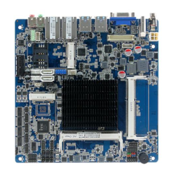
Page 16: Product Overview
EMX-BYT2 User’s Manual 2.1 Product Overview 16 EMX-BYT2 User’s Manual... - Page 17 User’s Manual • Main Memory EMX-BYT2 provides 2 x 204-pin DDR3L 1333MHz SODIMMs. SODIMM module. Note: The Platform requires DDR3L SODIMMs to be populated starting with the SODIMM at DIMM1. SODIMM SODIMM • SD Card USB Low & Full speed (@3.3V) Transmit traffic AF% less than 10% (max 50TB over lifespan) per port or use only High Speed or Super Speed USB devicesUSB Receive traffic is not affected.
- Page 18 –transferring data to or from the SD card-then removing the SD card, is not a concern. Customers have the option to enable a default D3 device setting to extend the life of the SD card interface, if supported by the OS. 18 EMX-BYT2 User’s Manual...
-
Page 19: Jumper And Connector List
Miscellaneous setting connector 1 5 x 2 header, pitch 2.54 mm FPT2 Miscellaneous setting connector 2 5 x 2 header, pitch 2.54 mm DIMM1/2 204-pin DDR3L DIMM socket FAUD1 Front Audio connector 5 x 2 header, pitch 2.54 mm EMX-BYT2 User’s Manual 19... - Page 20 4 x 1 wafer, pitch 2.54mm SPWR1/2 EC_Program 5 x 2 header, pitch 2.00 mm DC Power-in connector SIM1 SIM card slot HDMI1 HDMI connector LOUT1 Line-out audio jack MIC1 Mic-in audio jack VGA1 VGA connector 20 EMX-BYT2 User’s Manual...
-
Page 21: Setting Jumpers & Connectors
2.3.2 SATA2/MSATA1 mPCIe slot selector (JMSW1) SATA2 Connector * (SATA2 Connector enabled, MSATA1 slot Disabled) MSATA1 mPCIe slot (MSATA1 slot enabled, SATA2 Connector Disabled) * Default Note: SATA2/MSATA1 shared SATA signal, can not be used simultaneously. EMX-BYT2 User’s Manual 21... -
Page 22: Lvds Back Light Power Selection (Jsbkl1)
EMX-BYT2 User’s Manual 2.3.3 LVDS Back Light power selection (JSBKL1) PWM Mode*(Max current: 2A) DC Mode(Max current: 2A) * Default 2.3.4 AT/ATX Power Mode Select (JSATX1) ATX* * Default 22 EMX-BYT2 User’s Manual... -
Page 23: Clear Cmos (Cmos1)
User’s Manual 2.3.5 Clear CMOS (CMOS1) Protect* Clear CMOS * Default 2.3.6 LCD Inverter connector (JBKL1) Signal Max current +12V LVDS_BKLTEN LVDS_BKLADJ EMX-BYT2 User’s Manual 23... -
Page 24: Serial Port 1/2 Connector (Com1/2)
EMX-BYT2 User’s Manual 2.3.7 Serial port 1/2 connector (COM1/2) COM1 COM2 Signal PIN PIN Signal 2.3.8 Serial port 3/4/5/6 connector (COM3/4/5/6) COM6 COM5 COM4 COM3 Signal PIN PIN Signal 24 EMX-BYT2 User’s Manual... -
Page 25: Serial Port 1 Rs485/422 Mode Connector (Jrs485)
2.3.9 Serial Port 1 RS485/422 Mode connector (JRS485) RS-422 Signal PIN PIN Signal 422RX+ 422TX+ 422RX- 422TX- RS-485 Signal PIN PIN Signal 485TX+ 485TX- 2.3.10 General purpose I/O connector (DIO1) Signal PIN PIN Signal SMB_CLK SMB_DATA EMX-BYT2 User’s Manual 25... -
Page 26: Sata Power Connector 1/2 (Spwr1/2)
EMX-BYT2 User’s Manual 2.3.11 SATA Power connector 1/2 (SPWR1/2) SPWR1 SPWR2 Signal Max current +V5S_SATA +V12S_SATA 2.3.12 Power connector (PWR1) Signal Signal +VIN_12V +VIN_12V 26 EMX-BYT2 User’s Manual... -
Page 27: Usb Connector 3 (Usb3)
User’s Manual 2.3.13 USB connector 3 (USB3) Signal Signal +V5A_USB01 +V5A_USB01 USB_DN0 USB_DN1 USB_DP0 USB_DP1 2.3.14 Battery connector (BT1) Signal EMX-BYT2 User’s Manual 27... -
Page 28: Lvds Connector (Jlvds1)
2.3.15 LVDS connector (JLVDS1) Signal PIN PIN Signal +3.3V +3.3V EDP_DDC_SCL EDP_DDC_DAT LVDS_DATAP1 LVDS_DATAP0 LVDS_DATAN1 LVDS_DATAN0 LVDS_DATAP3 LVDS_DATAP2 LVDS_DATAN3 LVDS_DATAN2 LVDS_DATAP5 LVDS_DATAP4 LVDS_DATAN5 LVDS_DATAN4 LVDS_DATAP7 LVDS_DATAP6 LVDS_DATAN7 LVDS_DATAN6 LVDS_CLK2P LVDS_CLK1P LVDS_ CLK2N LVDS_ CLK1N +12V +12V 28 EMX-BYT2 User’s Manual... -
Page 29: Audio Connector (Faud1)
Audio connector (FAUD1) Signal PIN PIN Signal LINE2_JD LINE2_L SENSE_B MIC2_JD LINE2_R AUD_FRONT_DET MIC2_R MIC2_L 2.3.16.1 Signal Description –Front Audio connector (FAUD1) Signal Signal Description LINE2_JD AUDIO IN (LINE_RIN/LIN)sense pin MIC2_JD MIC IN (MIC_RIN/LIN) sense pin EMX-BYT2 User’s Manual 29... -
Page 30: Lpc Connector (Jlpc1)
EMX-BYT2 User’s Manual 2.3.17 LPC connector (JLPC1) Signal PIN PIN Signal LPC_SERIRQ LPC_DEG_CLK LPC_AD3 LPC_FRAME# LPC_AD2 PLT_RST# LPC_AD1 +3.3V LPC_AD0 2.3.18 EC_Program (EC1) Signal PIN PIN Signal EC_SMDATA_DBG 10 EC_SMCLK_DBG EC_HOLD# EC_FSMOSI EC_FSMIOSO EC_FSCK EC_FSCE# +3.3A_ECSPI 30 EMX-BYT2 User’s Manual... -
Page 31: Ps/2 Keyboard & Mouse Connector (Kbms1)
User’s Manual 2.3.19 PS/2 keyboard & mouse connector (KBMS1) Signal PIN PIN Signal KBDAT KBCK +5VSB MSDAT MSCK 2.3.20 BIOS connector (BIOS1) Signal PIN PIN Signal +V1.8A_SPI SPI_ROM_CS0# SPI_ROM_CLK SPI_ROM_R_MISO SPI_ROM_MOSI SPI_ROM_HOLD# EMX-BYT2 User’s Manual 31... -
Page 32: Sony/Philips Digital Interface (Spdif1)
EMX-BYT2 User’s Manual 2.3.21 Sony/Philips Digital Interface (SPDIF1) Signal SPDIF_OUT 2.3.22 Speaker connector (SPK1) Signal RSPK- RSPK+ LSPK- LSPK+ 32 EMX-BYT2 User’s Manual... -
Page 33: Miscellaneous Setting Connector 1 (Fpt1)
User’s Manual 2.3.23 Miscellaneous setting connector 1 (FPT1) Signal PIN PIN Signal +HD_LED +PWR_LED -HD_LED -PWE_LED +Reset +PWR_BNT -Reset -PWR_BNT 2.3.24 Miscellaneous setting connector 2 (FPT2) Signal PIN PIN Signal Speaker+ BLK_VR(10K) BLK_UP BLK_DN Speaker- EMX-BYT2 User’s Manual 33... -
Page 34: Led Indicator Connector 1 (Led1)
EMX-BYT2 User’s Manual 2.3.25 LED indicator connector 1 (LED1) Signal L1_1000#_LED L1_100#_LED L1_ACT_N L1_ACT_P 2.3.26 LED indicator connector 2 (LED2) Signal L2_1000#_LED L2_100#_LED L2_ACT_N L2_ACT_P 34 EMX-BYT2 User’s Manual... -
Page 35: Cpu Fan Connector (Fan1)
User’s Manual 2.3.27 CPU fan connector (FAN1) Signal +12V CPU_FANIN CPU_FANOUT EMX-BYT2 User’s Manual 35... -
Page 36: Bios Setup
EMX-BYT2 User’s Manual 3.BIOS Setup 36 EMX-BYT2 User’s Manual... -
Page 37: Introduction
If you do not press the keys at the correct time and the system does not boot, an error message will be displayed and you will again be asked to. Press F1 to Continue, DEL to enter SETUP EMX-BYT2 User’s Manual 37... -
Page 38: Using Setup
Note: Some of the navigation keys differ from one screen to another. To Display a Sub Menu Use the arrow keys to move the cursor to the sub menu you want. Then press <Enter>. A “” pointer marks all sub menus. 38 EMX-BYT2 User’s Manual... -
Page 39: Getting Help
BIOS Vendor and your systems manufacturer to provide the absolute maximum performance and reliability. Even a seemingly small change to the chipset setup has the potential for causing you to use the override. EMX-BYT2 User’s Manual 39... -
Page 40: Bios Setup
<Enter> to accept and enter the sub-menu. 3.6.1 Main Menu This section allows you to record some basic hardware configurations in your computer and set the system clock. 40 EMX-BYT2 User’s Manual... -
Page 41: System Language
Note: The BIOS setup screens shown in this chapter are for reference purposes only, and may not exactly match what you see on your screen. Visit the Avalue website (www.avalue.com.tw) to download the latest product and BIOS information. EMX-BYT2 User’s Manual 41... -
Page 42: Advanced Menu
EMX-BYT2 User’s Manual 3.6.2 Advanced Menu This section allows you to configure your CPU and other system devices for basic operation through the following sub-menus. 3.6.2.1 Trusted Computing 42 EMX-BYT2 User’s Manual... -
Page 43: Apci Settings
User’s Manual Item Options Description Enables or Disables BIOS support for security Disable, Security Device Support device. O.S. will not show Security Device. TCG EFI Enable[Default] protocol and INT1Ainterface will not be available. 3.6.2.2 APCI Settings EMX-BYT2 User’s Manual 43... - Page 44 EMX-BYT2 User’s Manual 44 EMX-BYT2 User’s Manual...
- Page 45 User’s Manual EMX-BYT2 User’s Manual 45...
- Page 46 Description Enable ACPI Auto Disabled[Default], Enables or Disables BIOS ACPI Auto Configuration Enabled Configuration. Enables or Disables System ability to Disabled Enable Hibernation Hibernate (OS/S4 Sleep State). This Enabled[Default], option may be not effective with some 46 EMX-BYT2 User’s Manual...
-
Page 47: It8528 Super Io Configuration
Set Parameters of Serial Port 1 (COMA). Serial Port 2 Configuration Set Parameters of Serial Port 2 (COMB). Serial Port 3 Configuration Set Parameters of Serial Port 3 (COMC). Serial Port 4 Configuration Set Parameters of Serial Port 4 (COMD). EMX-BYT2 User’s Manual 47... -
Page 48: Serial Port 1 Configuration
EMX-BYT2 User’s Manual Serial Port 5 Configuration Set Parameters of Serial Port 5 (COME). Serial Port 6 Configuration Set Parameters of Serial Port 6 (COMF). 3.6.2.3.1 Serial Port 1 Configuration 48 EMX-BYT2 User’s Manual... - Page 49 IO=3F8h; IRQ=3,4,5,6,7,9,10,11,12; Select an optimal setting for Change Settings IO=2F8h; IRQ=3,4,5,6,7,9,10,11,12; Super IO Device. IO=3E8h; IRQ=3,4,5,6,7,9,10,11,12; IO=2E8h; IRQ=3,4,5,6,7,9,10,11,12; UART 232[Default], Change the Serial Port as UART 232 422 485 UART 422, RS232/ 422/ 485 UART 485 EMX-BYT2 User’s Manual 49...
-
Page 50: Serial Port 2 Configuration
EMX-BYT2 User’s Manual 3.6.2.3.2 Serial Port 2 Configuration 50 EMX-BYT2 User’s Manual... - Page 51 User’s Manual Item Option Description Enabled[Default], Enable or Disable Serial Port Serial Port Disabled (COM). Auto[Default] IO=2F8h; IRQ=3; IO=3F8h; IRQ=3,4,5,6,7,9,10,11,12; Select an optimal setting for Change Settings IO=2F8h; IRQ=3,4,5,6,7,9,10,11,12; super IO Device. IO=3E8h; IRQ=3,4,5,6,7,9,10,11,12; IO=2E8h; IRQ=3,4,5,6,7,9,10,11,12; EMX-BYT2 User’s Manual 51...
-
Page 52: Serial Port 3 Configuration
EMX-BYT2 User’s Manual 3.6.2.3.3 Serial Port 3 Configuration 52 EMX-BYT2 User’s Manual... -
Page 53: Serial Port 4 Configuration
Enabled[Default], Enable or Disable Serial Port Serial Port Disabled (COM). Auto[Default] IO=3E8h; IRQ=5; IO=3E8h; IRQ=3,4,5,6,7,10,11,12; Select an optimal setting for Change Settings IO=2E8h; IRQ=3,4,5,6,7,10,11,12; super IO Device. IO=200h; IRQ=3,4,5,6,7,10,11,12; IO=208h; IRQ=3,4,5,6,7,10,11,12; 3.6.2.3.4 Serial Port 4 Configuration EMX-BYT2 User’s Manual 53... - Page 54 EMX-BYT2 User’s Manual Item Option Description Enabled[Default], Enable or Disable Serial Port Serial Port Disabled (COM). Auto[Default] IO=2E8h; IRQ=7; IO=3E8h; IRQ=3,4,5,6,7,10,11,12; Select an optimal setting for Change Settings IO=2E8h; IRQ=3,4,5,6,7,10,11,12; super IO Device. IO=200h; IRQ=3,4,5,6,7,10,11,12; IO=208h; IRQ=3,4,5,6,7,10,11,12; 54 EMX-BYT2 User’s Manual...
-
Page 55: Serial Port 5 Configuration
User’s Manual 3.6.2.3.5 Serial Port 5 Configuration EMX-BYT2 User’s Manual 55... - Page 56 EMX-BYT2 User’s Manual Item Option Description Enabled[Default], Enable or Disable Serial Port Serial Port Disabled (COM). Auto[Default] IO=200h; IRQ=11; IO=3E8h; IRQ=3,4,5,6,7,10,11,12; Select an optimal setting for Change Settings IO=2E8h; IRQ=3,4,5,6,7,10,11,12; super IO Device. IO=200h; IRQ=3,4,5,6,7,10,11,12; IO=208h; IRQ=3,4,5,6,7,10,11,12; 56 EMX-BYT2 User’s Manual...
-
Page 57: Serial Port 6 Configuration
3.6.2.3.6 Serial Port 6 Configuration Item Option Description Enabled[Default], Enable or Disable Serial Port Serial Port Disabled (COM). Auto[Default] IO=208h; IRQ=10; IO=3E8h; IRQ=3,4,5,6,7,10,11,12; Select an optimal setting for Change Settings IO=2E8h; IRQ=3,4,5,6,7,10,11,12; super IO Device. IO=200h; IRQ=3,4,5,6,7,10,11,12; IO=208h; IRQ=3,4,5,6,7,10,11,12; EMX-BYT2 User’s Manual 57... -
Page 58: H/W Monitor
EMX-BYT2 User’s Manual 3.6.2.4 H/W Monitor 58 EMX-BYT2 User’s Manual... -
Page 59: Smart Fan Mode Configuration
User’s Manual Item Options Description Enabled, Smart Fan Function Enable or Disable Smart Fan. Disabled[Default] 3.6.2.4.1 Smart Fan Mode Configuration EMX-BYT2 User’s Manual 59... - Page 60 Item Option Description Manual Mode[Default], Mode 01 Mode 02 Mode 03 CPU Smart Fan Mode Mode 04 CPU Smart Fan Mode Select. Mode 05 Mode 06 Mode 07 Mode 08 Fan PWM 0-255 Fan PWM duty. 60 EMX-BYT2 User’s Manual...
-
Page 61: S5 Rtc Wake Settings
User’s Manual 3.6.2.5 S5 RTC Wake Settings EMX-BYT2 User’s Manual 61... - Page 62 Time, System will wake on the current time + Increase minute(s). Disabled[Default], Wake up day of week. (Monday-Friday) or Wake up day of week Monday-Friday (Monday-Saturday). Monday-Saturday Wake up day 1-31 Select 0 for daily system wake up 1-31 for 62 EMX-BYT2 User’s Manual...
-
Page 63: Serial Port Console Redirection
Select 0-23 For example enter 3 for 3am and Wake up minute 0-23 15 for 3pm. Select 0-23 For example enter 3 for 3am and Wake up second 0-23 15 for 3pm. 1 – 5. Wake up minute increase 3.6.2.6 Serial Port Console Redirection EMX-BYT2 User’s Manual 63... -
Page 64: Com1
They can be used as an additional data bit. Stop bits indicate the end of a serial data 1[Default] Stop Bits packet. (A start bit indicates the beginning). The standard setting is 1 stop bit. 64 EMX-BYT2 User’s Manual... - Page 65 The Settings specify if BootLoader is selected then Legacy console redirection is Always Enable[Default] disabled before booting to Legacy OS. Redirection After BIOS POST BootLoader Default value is Always Enable which means Legacy console Redirection is enabled for Legacy OS. EMX-BYT2 User’s Manual 65...
-
Page 66: Cpu Configuration
EMX-BYT2 User’s Manual 3.6.2.7 CPU Configuration Use the CPU configuration menu to view detailed CPU specification and configure the CPU. 66 EMX-BYT2 User’s Manual... - Page 67 User’s Manual EMX-BYT2 User’s Manual 67...
- Page 68 EMX-BYT2 User’s Manual 68 EMX-BYT2 User’s Manual...
-
Page 69: Socket 0 Cpu Information
Enterprise 3 Update 3.) When enabled, a VMM can utilize the Disabled, Intel Virtualization Technology additional hardware capabilities provided by Enabled[Default] Virtualization Technology. Disabled[Default], Power Technology Energy Efficient Enable the power management features. Custom 3.6.2.7.1 Socket 0 CPU Information EMX-BYT2 User’s Manual 69... -
Page 70: Ppm Configuration
EMX-BYT2 User’s Manual 3.6.2.8 PPM Configuration 70 EMX-BYT2 User’s Manual... - Page 71 User’s Manual Item Options Description Disabled[Default], CPU C state Report Enable/Disable CPU C state report to OS. Enabled This option controls Max C state that the Max CPU C-state C1/C6/C7[Default] processor will support. EMX-BYT2 User’s Manual 71...
-
Page 72: Ide Configuration
EMX-BYT2 User’s Manual 3.6.2.9 IDE Configuration 72 EMX-BYT2 User’s Manual... - Page 73 User’s Manual EMX-BYT2 User’s Manual 73...
- Page 74 EMX-BYT2 User’s Manual 74 EMX-BYT2 User’s Manual...
- Page 75 SATA Speed Support Gen1 or Gen2. Gen2[Default] Port0 ODD SATA ODD Port Port1 ODD SATA ODD is Port0 or Port1. No ODD[Default] IDE Mode SATA Mode Select IDE/AHCI. AHCI Mode[Default] Enabled[Default] Serial-ATA Port 0/1 Enable/Disable Serial ATA Port0/1. Disabled, EMX-BYT2 User’s Manual 75...
-
Page 76: Lpss & Scc Configuration
EMX-BYT2 User’s Manual 3.6.2.10 LPSS & SCC Configuration 76 EMX-BYT2 User’s Manual... - Page 77 User’s Manual EMX-BYT2 User’s Manual 77...
- Page 78 EMX-BYT2 User’s Manual 78 EMX-BYT2 User’s Manual...
- Page 79 Disabled[Default] be erased. Enabled[Default] SCC SDIO Support SCC SDIO Support Enable/Disable. Disabled, Enabled[Default] SCC SD Card Support SCC SD Card Support Enable/Disable. Disabled, Enabled[Default] Disable/Enable SDR25 Capability in SD SDR25 Support for SDCard Disabled, Card controller. EMX-BYT2 User’s Manual 79...
-
Page 80: Network Stack Configuration
EMX-BYT2 User’s Manual 3.6.2.11 Network Stack Configuration Item Options Description Enabled Network Stack Enable/Disable UEFI Network Stack. Disabled[Default] 80 EMX-BYT2 User’s Manual... -
Page 81: Csm Configuration
User’s Manual 3.6.2.12 CSM Configuration EMX-BYT2 User’s Manual 81... - Page 82 EMX-BYT2 User’s Manual 82 EMX-BYT2 User’s Manual...
- Page 83 User’s Manual EMX-BYT2 User’s Manual 83...
- Page 84 EMX-BYT2 User’s Manual 84 EMX-BYT2 User’s Manual...
- Page 85 Legacy[Default] Do not launch Controls the execution of UEFI and Legacy Video UEFI Video OpROM. Legacy[Default] Do not launch Determines OpROM execution policy for Other PCI devices UEFI[Default] devices other than Network, Storage, or Legacy Video. EMX-BYT2 User’s Manual 85...
-
Page 86: Sdio Configuration
Auto Option: Access SD device in DMA Auto[Default] mode if controller supports it , otherwise in SDIO Access Mode PIO mode. DMA Option: Access SD device in DMA mode. PIO Option: Access SD device in PIO mode. 86 EMX-BYT2 User’s Manual... -
Page 87: Usb Configuration
User’s Manual 3.6.2.14 USB Configuration The USB Configuration menu helps read USB information and configures USB settings. EMX-BYT2 User’s Manual 87... - Page 88 EMX-BYT2 User’s Manual 88 EMX-BYT2 User’s Manual...
- Page 89 User’s Manual EMX-BYT2 User’s Manual 89...
- Page 90 EMX-BYT2 User’s Manual 90 EMX-BYT2 User’s Manual...
- Page 91 Mass storage device emulation type. ‘AUTO’ Auto[Default] Floppy enumerates devices according to their media format. Optical drives are emulated as ‘CDROM’, Generic-SD/MMC 1.00 Forced FDD Hard Disk drives with no media will be emulated according CD-ROM to a drive type. EMX-BYT2 User’s Manual 91...
-
Page 92: Security Configuration
EMX-BYT2 User’s Manual 3.6.2.15 Security Configuration 92 EMX-BYT2 User’s Manual... - Page 93 Enable/Disable BIOS AT Code from Running. Enabled, Disabled[Default] Inter® AT Platform PBA Enable/Disable BIOS AT Code from Running. Enabled TXE OVERWRITE. NORMAL: OverWrite Pin as high. OVERWRITE TXE OVERWRITE (TXE enabled) OVERWRITE:OverWrite Pin as low. NORMAL[Default] (TXE disabled). EMX-BYT2 User’s Manual 93...
-
Page 94: Lan Driver Report Status
EMX-BYT2 User’s Manual 3.6.2.16 Lan driver report status 94 EMX-BYT2 User’s Manual... -
Page 95: Chipset
User’s Manual 3.6.3 Chipset 3.6.3.1 North Bridge EMX-BYT2 User’s Manual 95... -
Page 96: Intel Igd Configuration
EMX-BYT2 User’s Manual Item Option Description Dynamic 2 GB 2.25 GB Max TOLUD Maximum Value of TOLUD. 2.5 GB 2.75 GB 3 GB[Default] 3.6.3.1.1 Intel IGD Configuration 96 EMX-BYT2 User’s Manual... - Page 97 User’s Manual EMX-BYT2 User’s Manual 97...
- Page 98 EMX-BYT2 User’s Manual 98 EMX-BYT2 User’s Manual...
- Page 99 User’s Manual EMX-BYT2 User’s Manual 99...
- Page 100 EMX-BYT2 User’s Manual 100 EMX-BYT2 User’s Manual...
- Page 101 DVMT Pre-Allocated 384M/416M/448M/ by the Internal Graphics Device. 480M/512M 128MB Select DVMT 5.0 Total Graphics DVMT Total Gfx Mem 256MB[Default] Memory size used by the Internal Graphics Device. 128MB Aperture Size Select the Aperture Size. 256MB[Default] EMX-BYT2 User’s Manual 101...
-
Page 102: Igd - Lcd Control
EMX-BYT2 User’s Manual 3.6.3.1.2 IGD - LCD Control 102 EMX-BYT2 User’s Manual... - Page 103 User’s Manual EMX-BYT2 User’s Manual 103...
- Page 104 Option Description Enabled[Default] Active Internal LVDS(eDP->Ch7511- Active LVDS (Ch7511) to –LVDS). Disabled 1024x768 24/1[Default] 800x600 18/1 1024x768 18/1 Port1-EDP to LVDS (Chrontel 7511) Panel CH7511 EDID Panel Option 1366x768 18/1 EDID Option. 1024x600 18/1 1280x800 18/1 104 EMX-BYT2 User’s Manual...
-
Page 105: South Bridge
LVDS Brightness Control Method. 1.BIOS Brightness Control Method BR Button 2.Brightness Button 3.Variable Resistor. LVDS Back Light PWM Select LVDS back light PWM duty. 100%[Default] 200[Default] LVDS Back Light PWM Select LVDS back light PWM Frequency. Frequency 3.6.3.2 South Bridge EMX-BYT2 User’s Manual 105... - Page 106 EMX-BYT2 User’s Manual 106 EMX-BYT2 User’s Manual...
- Page 107 Enable or Disable the High High Precision Timer Enabled[Default] Precision Event Timer. 11db 14db AUD Gain Setting Select db Value of the AUD Gain. 19db[Default] 25db PCIE x1 Select PCIE x1/ MPCIE of the PCIEX1 Setting MPCIE[Default] PCIEx1_SET EMX-BYT2 User’s Manual 107...
-
Page 108: Azalia Hd Audio
EMX-BYT2 User’s Manual 3.6.3.2.1 Azalia HD Audio 108 EMX-BYT2 User’s Manual... -
Page 109: Usb Configuration
Disabled = Azalia will be unconditionally Enabled[Default], Audio Controller disabled. Enabled = Azalia will be Disabled unconditionally Enabled. Auto = Azalia will be enabled if present disabled otherwise. Enabled[Default], HDMI Port B Enable/Disable HDMI Port B. Disabled 3.6.3.2.2 USB Configuration EMX-BYT2 User’s Manual 109... -
Page 110: Pci Express Configuration
EMX-BYT2 User’s Manual Item Option Description Windows 8.X[Default] OS Selection Android OS Selection. Windows 7 3.6.3.2.3 PCI Express Configuration 110 EMX-BYT2 User’s Manual... - Page 111 User’s Manual Item Option Description Enabled[Default], Enable or Disable the PCI Express Port PCI Express Port 0/1/2/3 Disabled 0/1/2/3 in the Chipset. Auto[Default] Speed Gen 2 Configure PCIe Port Speed. Gen 1 EMX-BYT2 User’s Manual 111...
-
Page 112: Security
EMX-BYT2 User’s Manual 3.6.4 Security Administrator Password Set setup Administrator Password User Password Set User Password 112 EMX-BYT2 User’s Manual... -
Page 113: Secure Boot Menu
User mode with enrolled Platform Enabled Key(PK) 2.CSM function is disabled. Secure Boot mode selector. ‘Custom’ Mode Standard Secure Boot Mode enables users to change Image Execution Custom[Default] policy and manage Secure Boot Keys. EMX-BYT2 User’s Manual 113... -
Page 114: Key Management
EMX-BYT2 User’s Manual 3.6.4.1.1 Key Management Item Option Description Enabled, Install Factory default Secure Boot Keys Default Key Provision Disabled[Default] when System is in Setup Mode. 3.6.5 Boot 114 EMX-BYT2 User’s Manual... -
Page 115: Save And Exit
BIOS setting. Launch EFI Shell from Attempts to Launch EFI Shell application (Shellx64.efi) from one of the filesystem device available filesystem devices. EMX-BYT2 User’s Manual 115... -
Page 116: Drivers Installation
EMX-BYT2 User’s Manual 4. Drivers Installation Note: Installation procedures and screen shots in this section are for your reference and may not be exactly the same as shown on your screen. 116 EMX-BYT2 User’s Manual... -
Page 117: Install Chipset Driver
Windows 8.1 operation system. If the warning message appears while the installation process, click Continue to go on. Step 3. Click Install. Step1. Click Next. Step 4. Click Finish to complete setup. Step 2. Click Accept. EMX-BYT2 User’s Manual 117... -
Page 118: Install Txe Driver
If the warning message appears while the installation process, click Continue to go on. Step 3. Click Next to continue installation. Step 4. Click Finish to complete setup. Step1. Click Next to start installation. Step 2. Click Next. 118 EMX-BYT2 User’s Manual... -
Page 119: Install Vga Driver
Windows 8.1 operation system. Step 3. Click Next. Step 1. Click Next to continue installation. Step 4. Click Next. Step 2. Step 5. Click Finish to complete setup. Click Yes to accept license agreement. EMX-BYT2 User’s Manual 119... -
Page 120: Install Audio Driver
Note: The installation procedures and screen shots in this section are based on Windows 8.1 operation system. Step 1. Click Next to continue setup. Step 2. Click Finish to complete the setup. 120 EMX-BYT2 User’s Manual... -
Page 121: Install Ethernet Driver
Windows 8.1 operation system. Step 3. Click Next. Step 4. Click Install to proceed. Step 1. Click Next. Step 2. Click Next to accept license Step 5. Click Finish to complete the setup agreement. EMX-BYT2 User’s Manual 121... -
Page 122: Install Usb 3.0 Driver
Continue to go on. Step 3. Click Next to continue installation. Step 4. Wait while installing. Step1. Click Next to start installation. Step 2. Click Yes. Step 5. Click Finish to complete setup. 122 EMX-BYT2 User’s Manual... -
Page 123: Install Mbi Driver
If the warning message appears while the installation process, click Continue to go on. Step 3. Click Next to continue installation. Step 4. Click Finish to complete setup. Step1. Click Next to start installation. Step 2. Click Yes. EMX-BYT2 User’s Manual 123... -
Page 124: Mechanical Drawing
EMX-BYT2 User’s Manual 5. Mechanical Drawing 124 EMX-BYT2 User’s Manual... - Page 125 User’s Manual Unit: mm EMX-BYT2 User’s Manual 125...
Need help?
Do you have a question about the EMX-BYT2 and is the answer not in the manual?
Questions and answers