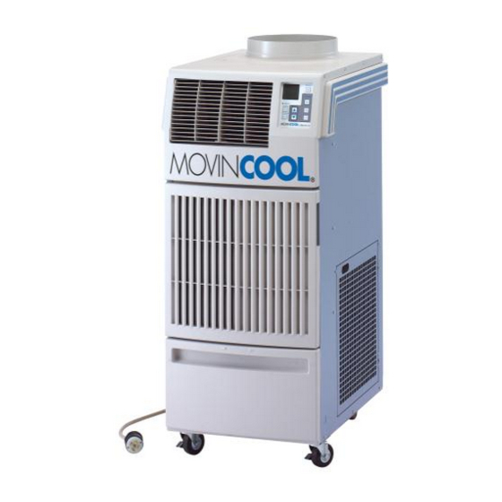
Movincool Office Pro 24 Service Manual
Movincool office pro 24 portable air conditioner service manual
Hide thumbs
Also See for Office Pro 24:
- Service manual (68 pages) ,
- Installation manual (2 pages) ,
- Operation manual (76 pages)

Related Manuals for Movincool Office Pro 24


Summary of Contents for Movincool Office Pro 24
- Page 1 M A N U A L S E R V I C E OFFICE PRO 24 DENSO SALES CALIFORNIA, INC. REGISTERED TO ISO 9002 FILE NO. A5537...
- Page 2 All rights reserved. This book may not be reproduced or copied, in whole or in part, without the written permission of the publisher. DENSO SALES CALIFORNIA, INC. reserves the right to make changes without prior notice. MovinCool is a registerd trademark of DENSO Corporation.
- Page 3 S E R V I C E M A N U A L O F F I C E P R O 2 4...
-
Page 5: Foreword
FOREWORD This manual has been published to service the MovinCool Office Pro 24. Please use this service manual only when servicing the Office Pro 24. DEFINITION OF TERMS WARNING: Describes precautions that should be observed in order to prevent injury to the user during installation or unit operation. -
Page 7: Table Of Contents
TABLE OF CONTENTS FOREWORD ..........................i DEFINITION OF TERMS ......................i GENERAL PRECAUTIONS ......................i TABLE OF CONTENTS ......................iii GENERAL DESCRIPTION ......................1 CONSTRUCTION, SPECIFICATIONS, & DATA ............... 3 REFRIGERANT SYSTEM ......................9 ELECTRICAL SYSTEM ......................13 TROUBLESHOOTING & REPAIR ................... 19... -
Page 9: General Description
(condenser) to exhaust exchanged heat to the outdoors. Unlike conventional air conditioners, the MovinCool Spot Cooling System is a spot cooler EVAPORATOR which directs cool air to particular areas or objects. - Page 10 GENERAL DESCRIPTION...
-
Page 11: Construction, Specifications, & Data
CONSTRUCTION, SPECIFICATIONS, and DATA EXHAUST AIR DUCT COOL AIR VENT CENTRIFUGAL FAN EVAPORATOR CONDENSER CAPILLARY TUBES DRAIN TANK COMPRESSOR CONTROL BOX DRAIN SWITCH Figure 2-1: Construction of Office Pro 24... - Page 12 CONSTRUCTION, SPECIFICATIONS, and DATA EVAPORATOR FAN CONTROL PANEL TOP PANEL EXHAUST AIR VENT RIGHT HANDLE COOL AIR VENT SIDE PANEL FAN MOTOR FRONT PANEL CONDENSER FAN CAPILLARY TUBE EVAPORATOR COMPRESSOR ACCUMULATOR DRAIN TANK CONDENSER CASTER POWER CORD Figure 2-2: Construction Diagram...
- Page 13 CONSTRUCTION, SPECIFICATIONS, and DATA 1. Basic Construction The MovinCool Spot Cooling System is compact in construction because the condenser and the evaporator ar e enclosed in one unit. The interior is divided into thr ee sections. The upper fr ont face is equipped with the evaporator , while the lower fr ont face contains the drain tank.
- Page 14 CONSTRUCTION, SPECIFICATIONS, and DATA Rating Conditions dry bulb ..............95º F (35º C) wet bulb ..............83º F (28.2º C) humidity ..............(60%) Specifications power frequency ............60Hz line voltage ..............single phase 208/230V power consumption ...........2.7 Kw current consumption ..........13.1/11.8 Amps power factor ...............99% starting current ............
- Page 15 CONSTRUCTION, SPECIFICATIONS, and DATA ø11.575 4.60 12.40 20.67 2.20 16.50 27.40 19.30 Figure 2-4: Exterior Dimensions (units: inches)
- Page 16 DATA @ 115V @ 115V 3.6 (14.3) 14 (25.2) 3.2 (12.7) 12 (21.6) 10 (18.0) 2.8 (11.1) 8 (14.4) 2.4 (9.5) 6 (10.8) 2.0 (7.9) Relative Humidity of Inlet Air (%) 35 (95) Cool Air Temperature Difference Curve 30 (86) 25 (77) @ 115V 20 (68)
-
Page 17: Refrigerant System
REFRIGERANT SYSTEM 1. The component par ts of the r e frigerant system include the following: • Compr essor • Evaporator • Condenser • Accumulator • Capillary tube These par ts ar e all connected by copper tubing. All the connections have been brazed. EVAPORATOR CONDENSER CAPILLARY... - Page 18 REFRIGERANT SYSTEM 2. Compressor The compr essor used for the unit is her metically sealed. The compr essor and the compr essor motor ar e in one casing. A. Compr essor Constr uction The constr uction of a r otar y type compr essor is divided into two mechanisms.
- Page 19 REFRIGERANT SYSTEM 4. Capillar y Tubes High Temp. / High Press. The capillar y tubes ar e a long thin tubes utilizing Liquid Refrigerant line flow r esistance to ser ve as an expansion valve. The length and the inner diameter of the capillar y tubes ar e deter mined by the capacity of the r efrigeration system, specified operating conditions, and the amount of r efrigerant.
- Page 20 REFRIGERANT SYSTEM EVAPORATOR INLET PIPE CONDENSER OUTLET PIPE EVAPORATOR OUTLET PIPE COMPRESSOR ASSY SUCTION PIPE (Insulated) COMPRESSOR CAPILLARY TUBE DISCHARGE PIPE CONDENSER INLET PIPE HIGH PRESSURE SWITCH PIPE (Condenser to Capillary Tube) CONNECTING PIPE (Evaporator to Compressor) Figure 3-5: Refrigerant System Piping...
-
Page 21: Electrical System
ELECTRICAL SYSTEM HPRS G T R IOLC J101 J102 J103 J104 J8 (AUX1) IOLF J201 Attachment Plug IOLC Internal Overload Protector of Compressor Terminal Block IOLF Internal Overload Protector of Fan Motor Control Board HPRS High Pressure Switch Relay Board Full Drain Warning Switch Fan Motor Freeze Protection Thermistor... - Page 22 ELECTRICAL SYSTEM 1. Basic Operation of Of fice Pr o 24 Electrical Cir cuit Ther e ar e two basic components used to contr ol the operation of the Classic Plus 26 Electrical System: • Contr ol Panel Assembly • Contr ol Box The Contr ol Panel Assembly contains the Contr ol Panel, Contr ol Boar d (with inputs for the fr eeze and...
- Page 23 ELECTRICAL SYSTEM 2. Control Box A. Capacitors The capacitors ar e used to temporarily boost the power output available to the fan motor and the compr essor at star t-up. Relay Board The specifications of each capacitor ar Relay Board DIP Switch listed below: Fuse...
- Page 24 ELECTRICAL SYSTEM 3. Fan Motor The fan motor is a single phase, induction type two-speed motor . The motor r otates fans on the evaporator side and the condenser side at the same time. Specifications: Rated V oltage: 230 volts 60 Hz Rated Output: 480 watts 410 watts CF1 (White)
- Page 25 The Of fice Pr o 24 model comes standar d with a drain tank, which collects the water that for ms on the evaporator during nor mal cooling operation. If the MovinCool unit is r equir ed to operate continuously without periodic emptying of this tank, a condensate pump may be needed.
- Page 26 ELECTRICAL SYSTEM 10. Compressor Pr otection Ther e is a T ime Delay pr ogram within the micr oprocessor . This pr events a heavy load fr om being applied on the Compr essor Motor when r estar ting the unit (Cool Mode) after a ver y shor t period of time.
-
Page 27: Troubleshooting & Repair
TROUBLESHOOTING AND REPAIR Before troubleshooting the system, the following inspection should be performed. 1. Inspection of Power Source Voltage Check the voltage of the power source. Single phase 230 volts (60Hz) Check the operation and condition of the fuse or circuit breaker in the power source. 2. -
Page 28: Troubleshooting And Repair
TROUBLESHOOTING AND REPAIR In case of trouble, perform the following inspection before disassembly. 5. Inspection of Plate Fins To inspect the plate fins of either the evaporator or condenser you must remove the air filters. After removal of the air filters, inspect the plate fins for any dirt, dust, lint, or debris that may have caused poor cooling performance of the unit. - Page 29 TROUBLESHOOTING AND REPAIR 8. Disassembly Control Panel Top Front Panel Right Handle Upper Rear Panel Right Panel Air Outlet Grille Left Handle Filter Element Front Panel Filter Assy Side Panel Filter Door Filter Element Room Thermistor Left Panel Blower Housing (evap.) Blower Housing Condenser Fan Drain Pan Assy...
- Page 30 TROUBLESHOOTING AND REPAIR A. Remove drain tank. Figure 5-5: Removal of Drain Tank B. Remove four (4) screws from upper front panel. Figure 5-6: Removal of Upper Front Panel Screws C. Slide upper front panel forward and remove. Figure 5-7: Removal of Upper Front Panel...
- Page 31 TROUBLESHOOTING AND REPAIR D. Louver can be removed from upper front panel by unsnapping the lock tap and remov- ing the louver from its pivots. PIVOTS TABS Figure 5-8: Removal of Air Outlet Louver E. Remove four (4) screws from service panel. Figure 5-9: Removal of Service Panel Disconnect the three (3) lead wires of the power cord.
-
Page 32: Removal Of Electrical Parts
TROUBLESHOOTING AND REPAIR G. Remove thirteen (13) screws from rear panel. " H. Remove ten (10) screws (eight shown) from upper rear panel and two (2) screws on top. Figure 5-11: Removal of Back and Upper Rear panel Screws 9. Removal of Electrical Parts HPRS G T R IOLC... - Page 33 TROUBLESHOOTING AND REPAIR To Terminal Block To Compressor To Fan Motor (R-Terminal) (High Speed) To Fan Motor Relay Board Ground To Terminal Block (Low Speed) (not used) (T-Terminal) DIP Switch Temperature Scale Display Switch Relay Board Fuse Fan Mode Control Switch STOP OPERATE Main Wiring Harness...
- Page 34 TROUBLESHOOTING AND REPAIR 10. Removal of Blower Assembly Control Panel Right Stay Control Panel Left Stay Air Deflector Evaporator Fan Casing Evaporator Fan Motor Stay Middle Frame Sub-Assy Fan Motor Condenser Fan Casing Assy Condenser Fan Ring Sub-Assy Figure 5-15: Disassembly of Blower...
- Page 35 TROUBLESHOOTING AND REPAIR A. Remove the ring sub-assy Figure 5-16: Removal of Ring Sub-Assy B. Loosen the set screw using an allen wrench and then remove the centrifugal fan. Figure 5-17: Removal of Centrifugal Fan C. Remove the two (2) nuts “A” on the inside of the housing in the locations shown.
- Page 36 TROUBLESHOOTING AND REPAIR E. Remove the centrifugal fan by loosening the set screw on the shaft. Remove the fan motor by loosening nuts “A”. Figure 5-20: Removal of Fan Motor Remove seven (7) screws from left side panel. Figure 5-21: Removal of Screws for Left Side Panel G.
- Page 37 TROUBLESHOOTING AND REPAIR Remove two (2) screws from the control panel stay. Figure 5-24: Removal of Control Panel J. Remove two (2) screws from the control panel stay. Figure 5-25: Removal of Control Panel K. Disconnect the following connectors from the (B) (C) (D)(E) control board: (A) Wire Harness, Relay Board to Control...
- Page 38 TROUBLESHOOTING AND REPAIR board on the control panel assembly. Remove the control board. 11. Inspection of Capacitor (for Fan Motor and Compressor) Ohmeter Method – Set the ohmeter to the 100KΩ range. Place the two probes against the two terminals of the capacitor. At first, the ohmeter should indicate 0Ω, then the reading should gradually increase towards infinity (∞).
- Page 39 TROUBLESHOOTING AND REPAIR 15. Inspection of Compressor Motor Measure resistance across the terminals of the compressor motor. Terminals (at 77˚F (25˚C)) Approx. 2.0Ω Approx. 2.2Ω Approx. 3.8Ω If the measured resistance is not equal to these standard values, replace the compressor. Figure 5-31: Inspection Of Compressor 16.
- Page 40 TROUBLESHOOTING AND REPAIR 19. Repair of Refrigerant System In case there is a leak, obstruction, or trouble in the refrigerant system of the Spot Cooling System, replace or repair the part in question. After replacing any component all connections must be brazed. A.
- Page 41 TROUBLESHOOTING AND REPAIR Removal of Refrigeration Cycle Components CAUTION 1. Before any refrigeration cycle component can be replaced, it is necessary to recover the refrigerant using standard recovery procedures and equipment. 2. To prevent oxidation, dry nitrogen should be conducted (flow rate 1l/min) through the pinch-off tube during any brazing operation.
- Page 42 TROUBLESHOOTING AND REPAIR 20. Charging the System with R-22 Refrigerant Always ensure that the refrigerant system has been properly evacuated before charging with the specified amount of R-22. WARNING When handling refrigerant (R-22), the following precautions should always be observed: •...
- Page 43 TROUBLESHOOTING AND REPAIR (3) Connect the charging hoses (red - high pressure side, blue - low pressure side) of the gauge manifold to the process tube fittings. NOTE: Connect the hoses using care not to mistake the high pressure side for the low pressure side and vice versa.
- Page 44 TROUBLESHOOTING AND REPAIR D. Checking Gas Leak (1) Remove the charging hose (green) from the vacuum pump, and connect the hose to the refrigerant cylinder (R22). Figure 5-40: Checking Gas leak (2) Loosen the nut on the gauge manifold side of the charging hose (green). (3) Open the high pressure valve of the gauge manifold.
- Page 45 TROUBLESHOOTING AND REPAIR 21. Refrigerant Charging Work A. Refrigerant Charging (1) Remove the charging hose (green) from the vacuum pump, and connect it to the refrigerant cylinder (R-22). (2) Loosen the nut on the gauge manifold side of the charging hose (green). Open the valve of the charging hose (green).
- Page 46 TROUBLESHOOTING AND REPAIR B. Removal of Gauge Manifold (1) Crimp the pinch-off tube with a pinch-off tool. (2) Remove the gauge manifold and the process tube fitting. Crush the end of the pinch-off tube. (3) Braze the end of the pinch-off tube. (4) Ensure that a gas leak is not present at the pinched off portion and the brazed end.
- Page 47 TROUBLESHOOTING AND REPAIR 26. Schematic Figure 5-48: Wiring Diagram...
- Page 48 TROUBLESHOOTING AND REPAIR...
- Page 49 DENSO SALES CALIFORNIA, INC. TECHNICAL SERVICE DEPARTMENT Second Issue: June 2000 DSCA P/N: LA990009-0531 Printed in U.S.A.
- Page 50 (800) 264-9573 www.movincool.com DSCA P/N: LA990009-0531...
Need help?
Do you have a question about the Office Pro 24 and is the answer not in the manual?
Questions and answers