Movincool office Pro 24 Service Manual
Hide thumbs
Also See for office Pro 24:
- Service manual (50 pages) ,
- Installation manual (2 pages) ,
- Operation manual (76 pages)

Related Manuals for Movincool office Pro 24


Summary of Contents for Movincool office Pro 24
- Page 1 MANUAL SERVICE OFFICE PRO 24 SERIAL NUMBER FROM APRIL 2007 (0407) TO PRESENT DocID: 00G00015E...
- Page 2 All rights reserved. This book may not be reproduced or copied, in whole or in part, without the written permission of the publisher. DENSO SALES CALIFORNIA, INC. reserves the right to make changes without prior notice. MovinCool is a registered trademark of DENSO Corporation.
-
Page 3: Table Of Contents
Basic Operation of The Office Pro 24 Electrical Circuit ....... . - Page 4 Table of Contents Control Box ..............24 Fan Motor .
- Page 5 Table of Contents Repair Section 7. TROUBLESHOOTING Troubleshooting ..............32 Self-Diagnostic Codes .
-
Page 6: Precautions For Safety
Operation Section 1. PRECAUTIONS FOR SAFETY 1.1 Foreword • This manual has been published to service the MovinCool Office Pro 24. Please use this service manual only when servicing the Office Pro 24. 1.2 Definition of Terms Describes precautions that should be observed in order to prevent injury to WARNING the user during installation or unit operation. -
Page 7: General Description
(Outdoor Unit) (Indoor Unit) exchanged heat to the outdoors. • Unlike conventional air conditioners, the MovinCool Office Pro 24 is a spot cooler which I000501 directs cool air to particular areas or objects. MovinCool Office Pro 24 has the following features: 2.2 Compact Design... -
Page 8: Construction
Operation Section 3. CONSTRUCTION 3.1 Exterior Dimensions (DIA. 11.6) (1.4) (1.4) (4.6) (20.9) (2.0) (3.5) (3.7) (27.4) (19.3) (Unit: inch) I002187... -
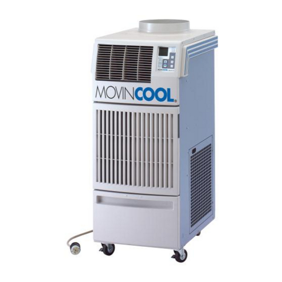
Page 9: Exterior Components
Operation Section 3.2 Exterior Components Operation Panel Cold Air Outlet Grill Evaporator Air Inlet Grill Condenser Air Outlet Duct Drain Tank Cover Caster Condenser Air Inlet Panel Power Cord Service Panel I002188... -
Page 10: Internal Structure
I002189 3.4 Basic Construction • The MovinCool Office Pro 24 is compact in construction because the condenser and the evaporator are enclosed in one unit. The interior is divided into three sections. The upper front face is equipped with the evaporator, and the lower front face contains the drain tank and condensate pump (Optional). -
Page 11: Air Flow
3.7 Drain Tank • A 5.0 gal (19 L) drain tank is supplied with the Office Pro 24. The condensate (water) is collected into the tank. The drain switch activates and stops the operation when tank reaches the level of approximately... -
Page 12: Technical Specifications
Operation Section 4. SPECIFICATIONS 4.1 Technical Specifications ITEM SPECIFICATIONS Electronic Features Control Panel Electronic Thermostat Control Electronic Cooling Capacity Capacity-208/230 V 23600/24000 Btu/h (6917/7034 W) Refrigerant Circuit Compressor Compression Type Hermetic Rotary Motor Rated Output at 230 V 1.83 kW Evaporator Plate Fin Condenser... - Page 13 Operation Section ITEM SPECIFICATIONS Operating Condition Inlet air: Maximum 95 °F (35 °C), 60 %RH Inlet air: Minimum 65 °F (18.3 °C), 50 %RH Sound Level With Condenser Duct-high/low 63/61 dB (A) Without Condenser Duct-high/low 65/63 dB (A) Max. Duct Equivalent Length-Per Cold Duct Hose/Hot Duct Hose 50/45 ft (15.2/13.7 m) Condensate Tank Capacity 5 ±...
-
Page 14: Characteristics (At 230 V)
Operation Section 4.2 Characteristics (at 230 V) <Cooling Capacity Curve > < Cool Air Temperature Difference Curve> 23.4(13) 21.6(12) 19.8(11) 18.0(10) 16.2(9) 14.4(8) 12.6(7) 95(35) 10.8(6) 86(30) 9.0(5) 77(25) 7.2(4) 68(20) Relative Humidity (%) (10) (15) (20) (25) Wet Bulb Temp. °F (°C) <Power Consumption Curve >... -
Page 15: Characteristics (At 208 V)
Operation Section 4.3 Characteristics (at 208 V) <Cooling Capacity Curve > < Cool Air Temperature Difference Curve> 23.4(13) 21.6(12) 19.8(11) 18.0(10) 16.2(9) 14.4(8) 12.6(7) 95(35) 10.8(6) 86(30) 9.0(5) 77(25) 7.2(4) 68(20) Relative Humidity (%) (10) (15) (20) (25) Wet Bulb Temp. °F (°C) <Power Consumption Curve >... -
Page 16: Refrigerant System Construction
Operation Section 5. REFRIGERANT SYSTEM 5.1 Refrigerant System Construction The component parts of the refrigerant system include the following: • Compressor, Evaporator, Condenser, Capillary tube, High Pressure Switch These parts are all connected by copper tubing. All the connections have been brazed. Condenser Evaporator Condenser... -
Page 17: Compressor
Operation Section 5.2 Compressor • The compressor used for the unit is hermetically sealed. The compressor and the compressor motor are in one casing. (1) Compressor construction •The construction of a rotary type compressor is divided into two mechanisms; the drive mechanism (compressor motor), and the compression mechanism (compressor). - Page 18 Operation Section (2) Basic compressor operation •The roller (compression mechanism) is set Discharge eccentrically with a certain distance given from Hole Spring Discharge the axis of the center of the cylinder. A spring Suction Valve Hole loaded blade is mounted on the cylinder. The Blade roller turns to compress the refrigerant in the space between the cylinder and eccentrically...
- Page 19 Operation Section (3) Operation 1) Start of compression 1) The cylinder is filled with low pressure gas. Discharge Blade Valve 2) Since pressure in the discharge chamber is higher than in the cylinder, the discharge valve is kept closed. Roller I001676 2) Suction and compression 1) The pressure in the cylinder increases...
-
Page 20: Condenser
Operation Section (4) Compressor lubrication •The lubrication system is comprised of a hollow shaft, an oil scraper mounted at the end face, hollow shaft, a shaft journal (shaft bearing), Rotor and the lubrication groove for the shaft journal. The lubrication groove is wider than the oil Hollow Shaft hole. -
Page 21: Evaporator
Operation Section 5.5 Evaporator • The evaporator, like the condenser, is a heat exchanger covered with plate fins. Heat is removed from the air being pulled across the evaporator by the centrifugal fan and the resulting cool air is expelled through the cool air vent. 5.6 High Pressure Switch •... -
Page 22: Electrical System
Operation Section 6. ELECTRICAL SYSTEM 6.1 Circuit Diagram and Control Box φ AC 208/230 V 1 60 Hz HPRS Jumper Line IOLC J101 J102 J103 J104 J106 J201 IOLF J108 J105 Attachment Plug I O L F Inner Overload Relay of Fan Motor T B 1 Terminal Block I O L C... -
Page 23: Basic Operation Of The Office Pro 24 Electrical Circuit
Operation Section 6.2 Basic Operation of The Office Pro 24 Electrical Circuit • There are two basic components used to control the operation of the Office Pro 24 electrical system: - Control panel assembly - Control box • The control panel assembly contains the control panel, control board (with inputs for the freeze and room temperature thermistors), drain switch, high pressure switch and a microprocessor. -
Page 24: Control Box
Operation Section 6.3 Control Box (1) Capacitors • The capacitors are used to temporarily boost the power output available to the fan motor and the compressor at start-up. • The specifications of each capacitor are listed below: Capacitor Application Voltage Rating Capacitance Fan Motor 440 VAC... - Page 25 Operation Section (2) Relay board • The relay board receives signals and outputs <Dip Switch> from the control board that contains a Dip Switch microprocessor. The relay board contains the Temperature Scale compressor, fan on and fan mode (speed) Display Switch (°C ⇔...
-
Page 26: Fan Motor
Operation Section 6.4 Fan Motor • The fan motor is a single phase, induction type two-speed motor. The motor rotates the fan on both the evaporator side and the condenser side at the same time. Specifications: CF1 (White) - Rated Voltage: 230 V, 60 Hz CF2 (Brown/White) Ground J5 Low (Red) -
Page 27: Power Cord With Lcdi
Operation Section 6.6 Power Cord with LCDI • Office Pro 24 is equipped with a UL approved LCDI cord and an approved NEMA plug configuration (6-20). The appropriate outlet must be used for this plug type. LCDI is used for monitoring leakage current. -
Page 28: Drain Switch
Operation Section 6.7 Drain Switch • The Office Pro 24 is equipped with a drain tank switch. When the drain tank accumulates approximately 4.0 gal (15 L) of condensate (water) in the drain tank, the drain tank switch sends a signal to the microprocessor. The microprocessor stops all operation of the unit, flashes the "TANK FULL”... -
Page 29: Condensate Pump Kit (Optional)
COOL ON/OFF button. The unit returns to the previous temperature set point. 6.8 Condensate Pump Kit (optional) • The Office Pro 24 model comes standard with a drain tank, which collect the water that forms on the evaporator during normal cooling operation. If the unit is required to operate continuously without periodic emptying of this tank, a condensate pump may be needed. -
Page 30: Fan Mode Control Switch
Operation Section 6.12 Fan Mode Control Switch • The fan motor operation is controlled by relays on the relay board through a microprocessor in the control panel assembly. The fan program in the microprocessor can be changed by a DIP switch on the left side of the relay board located in the control box. -
Page 31: Warning Signal Connection (Output Signal Terminal L+ And L-)
Operation Section 6.14 Warning Signal Connection (Output Signal Terminal L+ and L-) • The controller is equipped with a warning signal output relay type (Form C, normal open dry contact) which can be used to monitor the failure condition. Relay contactor is closed when the following condition has occurred: - Tank Full - Temperature sensor fails - High pressure switch error... -
Page 32: Troubleshooting
Repair Section 7. TROUBLESHOOTING 7.1 Troubleshooting • Before troubleshooting the system, the following inspection should be performed. (1) Inspection of power source voltage • Check the voltage of the power source. - Single phase 208/230 V (60 Hz) • Check the operation and condition of the fuse or circuit breaker in the power source. (2) Inspection of air filters •... -
Page 33: Self-Diagnostic Codes
Repair Section 7.2 Self-Diagnostic Codes • Self-diagnostic codes are displayed on the control board under the following conditions and clear method is as follows. LCD Display Description Condition Reset/Remedy Drain tank is full When the drain tank is filled with 1) Drain away. - Page 34 Repair Section LCD Display Description Condition Reset/Remedy Show LCD and LED Press HI/LO and buttons After 5 sec., display goes back to MO TU WE TH FR SA SU all on mode simultaneously for 3 sec. normal mode. START PROGRAM STOP (To check LCD segments and LED CLOCK...
-
Page 35: Troubleshooting Chart
Repair Section LCD Display Description Condition Reset/Remedy Activation of high When high pressure switch Find the cause of high pressure to pressure switch (connected to J104) activates address it. (=J104 input turns to open) 3 times Check the following. in 24 h, “HP” is indicated and signal Ambient air temperature SET TEMP output (J106) turns on. - Page 36 Repair Section Possible Cause Symptom Remedy Checking Area Cause 1. Usage conditions Operation near usage limits. Review the installation (high temperature). place. 2. Dirt in condenser or Insufficient heat exchange. Clean fins. evaporator. Compressor operates. 3. Frost in refrigeration cycle. Clogging at the frost section.
- Page 37 Repair Section (2) Unit does not start (operate) < NOTE > • In this case, there is a possibility of safety device activating due to the clogged air filter. So make sure to first clean the air filter and then start up again to confirm if the problem lies with the air filter. •...
- Page 38 Repair Section Possible Cause Symptom Remedy Checking Area Cause 1. Display code “FL”. Drain tank (optional) is filled Discharge the drain water. with the drain water. Improper drain switch Check connection. connection. Defective drain switch. Replace drain switch. 2. Display code “AS”. Improper routing of drain Repair drain hose, then reset hose.
- Page 39 Repair Section Possible Cause Symptom Remedy Checking Area Cause 1. Fan on-off relay on the relay Open circuit or insufficient Replace relay board. board. contact. 2. Fan HI/LO change relay on Open circuit or insufficient Replace relay board. the relay board. contact.
-
Page 40: Basic Inspection
Repair Section (4) Abnormal noise or vibration • To prevent abnormal noise or vibration, carefully determine the source of the problem and come up with proper countermeasures to solve the problem so that it does not occur again. Possible Cause Symptom Remedy Checking Area... - Page 41 Repair Section (3) Inspection of cooling capacity performance • Measure the difference in temperature between the inlet of the evaporator and the cool air vent. If the difference is out of the range given in the graphs on page 14 and 15, proceed with the remedy suggested in the troubleshooting chart on page 35 to 40.
-
Page 42: Parts Construction
Repair Section 8. DISASSEMBLY 8.1 Parts Construction Control Panel Upper Front Panel Right Handle Upper Panel Air Outlet Grill Right Panel Left Handle Filter Element Front Panel Filter Assy Right Panel Filter Assy Filter Element Room Thermistor Left Panel Blower Housing (Evaprator) Blower Housing(Condenser) Drain Pan Assy... -
Page 43: Disassembly
Repair Section 8.2 Disassembly 1) Remove drain tank. I002203 2) Remove four (4) screws from upper front panel. Screw (1) Screw (1) Screws (2) I002204 3) Slide upper front panel forward and remove. I002205 4) Louver can be removed from upper front panel by Pivots unsnapping the lock tap and removing the louver from its pivots. - Page 44 Repair Section 5) Remove seven (7) screws from service panel. Screws (7) I002207 6) Remove thirteen (13) screws from rear panel. Screws (3) Screws (7) Screws (3) I002208 7) Remove eight (8) screws from rear panel and two Screws (2) (2) screws from blower housing (condenser).
-
Page 45: Removal Of Electrical Parts
Repair Section 9) Remove seven (7) screws from right panel. Screws (7) I002211 8.3 Removal of Electrical Parts (1) Control box 1) Remove seven (7) screws from service panel. (See page 44.) 2) Remove electrical parts. - Terminal block: Remove two (2) screws from control box. - Terminal block (signal connection): Remove two (2) screws from control box. - Page 46 Repair Section (2) Relay board 1) Remove seven (7) screws from service panel. (See page 44.) 2) Disconnect seven (7) connectors, and remove five (5) screws from relay board. Temperature Scale Display Switch Dip Switch To Control Board(10 pin) Fan Mode Control Switch To Condensate Pump(2 pin) To Compressor (Black) Power (#T1) OnTerminal Block...
- Page 47 Repair Section 2) Remove four (4) screws from the control panel stay. Screws (2) Screws (2) I002214 3) Disconnect the following connectors from the control board: (A) J201 (10-pin) Wire Harness, Relay Board to Control (B) J101 (2-pin) Room Temperature Thermistor (C) J102 (2-pin with...
- Page 48 Repair Section 4) Remove the five (5) screws from the control board on the control panel assembly. Remove the control board. I001804...
- Page 49 Repair Section (4) Battery replacement of control board • When the power is unplugged from the unit, and control board is automatically resetting clock and program, it is time to change the battery on the control board to avoid resetting of clock and program.
-
Page 50: Removal Of Blower Assembly
Repair Section 8.4 Removal of Blower Assembly Control Panel Stay Control Panel Stay Air Deflector Evaporator Fan Casing Evaporator Fan Motor Stay Center Panel Fan Motor Condenser Fan Casing Condenser Fan Ring I002216... - Page 51 Repair Section (1) Removal of condenser fan 1) Loosen the set screw using a hex key. Then remove condenser fan. Set Screw I002217 (2) Removal of evaporator fan and fan motor 1) Remove two (2) nuts on the inside of the condenser fan casing in the locations shown.
-
Page 52: Inspection Of Capacitor (For Fan Motor And Compressor)
Repair Section 8.5 Inspection of Capacitor (for Fan Motor and Compressor) (1) Ohmmeter method • Set the ohm-meter to the 10M range. Place the two probes against the two terminals of the capacitor. At first, the ohm-meter should indicate small value, then the reading should gradually increase towards... -
Page 53: Inspection Of Fan Motor
Repair Section 8.7 Inspection of Fan Motor • Measure resistance across the terminals of the fan motor. (All terminals must be disconnected from the unit.) • Between terminals (at 77 °F (25 °C)) - J6-CF1 Approx. 6.2 ohm - J6-CF2 Approx. 13.0 ohm CF1 (White) - CF1-CF2 Approx. -
Page 54: Inspection
Repair Section 8.11 Inspection • In most cases, the probable cause for insufficient cooling is a clogged system, leakage or an incorrect amount of refrigerant. In such cases, inspect the system according to the following procedure. (1) Inspection of clogged system •... -
Page 55: Refrigerant System Repair
9. REFRIGERANT SYSTEM REPAIR 9.1 Repair of Refrigerant System • In case there is a leak, obstruction, or trouble in the refrigerant system of the Office Pro 24, replace or repair the part in question. After replacing any component all connections must be brazed. - Page 56 Repair Section (4) Use of dry nitrogen gas • During brazing, the inside of the pipe undergoes an oxidative reaction due to the brazing flame. Introduce dry nitrogen gas (0.27 gal/min (1 L/min); adjust with the flow regulator) through the pinch-off tube of the refrigerant.
-
Page 57: Removal Of Refrigeration Cycle Components
Repair Section 9.2 Removal of Refrigeration Cycle Components CAUTION • Before any refrigeration cycle component can be replaced, it is necessary to recover the refrigerant using standard recovery procedures and equipment. • To prevent oxidation, dry nitrogen should be conducted (flow rate 0.27 gal/min (1 L/min)) through the pinch-off tube during any brazing operation. -
Page 58: Charging The System With R-410A Refrigerant
Repair Section 9.3 Charging the System with R-410A Refrigerant • Always ensure that the refrigerant system has been properly evacuated before charging with the specified amount of R-410A. • Equipments is only for R-410A. • Liquid charge (no gas charge). •... - Page 59 Repair Section (1) Connection of gauge manifold 1) Properly remove the crushed end of the pinch-off tube at the high pressure side and the low Charging Hose Side pressure side of the refrigerant cycle with a pipe Refrigerant cutter. Cycle Side 2) Fit the process tube fitting to the pinch-off tube on both sides.
- Page 60 Repair Section (3) Checking vacuum 1) Leave the high pressure valve and the low Valve Setting Leave valves closed for 5 pressure valve of the gauge manifold closed for min or more. Pointer of Closed Closed pressure gauge returning to five min or more, and confirm that the gauge zero indicates there is a leak.
- Page 61 Repair Section (4) Checking gas leak 1) Remove the charging hose (green) from the Valve Setting vacuum pump, and connect the hose to the Closed Closed Air Purging refrigerant cylinder (R-410A). Open The Valve 2) Loosen the nut on the gauge manifold side of the of Refrigerant Cylinder charging hose (green).
- Page 62 Repair Section (5) Evacuation (repeat) 1) Close the valve of the refrigerant cylinder. Then Valve Setting remove the charging hose (green) from the Gauge Closed Open Closed Closed 30 inHg (100 kPa) or larger refrigerant cylinder, and connect it to the Low Pressure refrigerant recovery machine.
-
Page 63: Refrigerant Charging Work
Repair Section 9.4 Refrigerant Charging Work (1) Refrigerant charging 1) Remove the charging hose (green) from the Valve Setting vacuum pump, and connect it to the refrigerant Closed Closed Air Purging cylinder Open The Valve (R-410A). of Refrigerant Cylinder 2) Loosen the nut on the gauge manifold side of the charging hose (green). - Page 64 Repair Section (2) Removal of gauge manifold 1) Crimp the pinch-off tube with a pinch-off tool. Pinch-Off Tool 2) Remove the gauge manifold and the process To Gauge Manifold Side tube fitting. Crush the end of the pinch-off tube. Pinch-Off Tube 3) Braze the end of the pinch-off tube.
-
Page 65: Reassembly
Repair Section 10. REASSEMBLY 10.1 Removal of Unit • Reassemble the unit in the reverse order of removal. Described below are the parts that require special care in reassembling the unit. Perform all wiring or rewiring as referenced in the wiring diagram. -
Page 66: Perform The Inspection
Repair Section 10.5 Perform the Inspection • Perform the inspection of cooling performance and check for abnormal noise or abnormal vibration. 10.6 Caster Maintenance • Lubricate bearings in caster as needed with standard bearing grease using the zerk fitting. < NOTE > Casters should roll and swivel freely. -
Page 67: Schematic
Repair Section 10.7 Schematic <Wiring Diagram> φ AC 208/230 V 1 60 Hz HPRS Jumper Line IOLC J101 J102 J103 J104 J106 J201 IOLF J108 J105 Attachment Plug I O L F Inner Overload Relay of Fan Motor T B 1 Terminal Block I O L C Inner Overload Relay of Compressor... - Page 68 DENSO SALES CALIFORNIA, INC. Long Beach, CA 90810 www.movincool.com P/N: SV0004-01 Second Issue: December 2008...
Need help?
Do you have a question about the office Pro 24 and is the answer not in the manual?
Questions and answers