Movincool Climate Pro K36 Operation Manual
Hide thumbs
Also See for Climate Pro K36:
- Installation manual (4 pages) ,
- Accessory installation manual (4 pages) ,
- Service manual (88 pages)
Table of Contents
Advertisement
Advertisement
Table of Contents

Related Manuals for Movincool Climate Pro K36


Summary of Contents for Movincool Climate Pro K36
- Page 1 OPERATION MANUAL CLIMATE PRO K36 CLIMATE PRO K60 CLIMATE PRO K63...
-
Page 3: Serial Number Location
Please read this manual carefully and keep it for future reference. La versión en español está disponible en www.movincool.com La version française est disponible sur www.movincool.com © 2020 DENSO PRODUCTS AND SERVICES AMERICAS, INC. All rights reserved. MovinCool® and Climate Pro® are registered trademarks of DENSO Corporation. -
Page 4: Table Of Contents
TABLE OF CONTENTS SERIAL NUMBER LOCATION SAFETY PRECAUTIONS NAMES OF PARTS CONTROL PANEL Overview Home Screen Mode Screen Menu Screen Sett ing Screen INSTALLATION Placement of the Unit Accessories Typical Installation Options Plugging in the Unit LCDI (Leakage Current Detection Interrupter) Power Cord External Warning Device Connection External Alarm Device Connection INITIAL SETTINGS... - Page 5 Clearing Schedule Adjusting Brightness Fan Mode Changing Temperature Scale Key Lock Key Unlock Temporary Stop During Key Lock Service Information Self-Diagnostic Codes List of Self-Diagnostic Codes Emptying the Drain Tanks CONDENSATE PUMP KIT Removing the Tab Hose Installation Testing MAINTENANCE Cleaning Air Filters Cleaning the Unit Before Long Term Storage...
-
Page 6: Safety Precautions
SAFETY PRECAUTIONS This appliance is not intended for use by persons (including children) with reduced physical, sensory or mental capabilities, or lack of experience and knowledge, unless they have been given supervision or instruction. Children should be supervised to ensure that they do not play with the appliance. To reduce the risk of injury or property damage, read “Safety Precautions”... - Page 7 This may cause fire, electric shock, injury, water leaks or malfunction. Contact your MovinCool dealer or qualified technician. If the unit is soaked due to natural disaster, consult your MovinCool dealer. If you keep using the unit, it may result in fire, electric shock or malfunction.
- Page 8 CAUTION OPERATION Do not operate without panels or fan guards. Touching high-voltage, high-temperature or rotating parts may cause electric shock, injury or burns. Do not use the unit in sloping, non-level areas. Use the unit only on a smooth, flat, level surface. There is a risk of electric shock due to water leaks or injury due to toppling.
- Page 9 Unlock the caster to move the unit. Failure to unlock the caster may cause injury due to falling. When the tanks are full, empty water immediately. Water leaks from the unit may cause property damage, or injury due to wet floor. Never pull the power cord to disconnect the unit from the outlet.
-
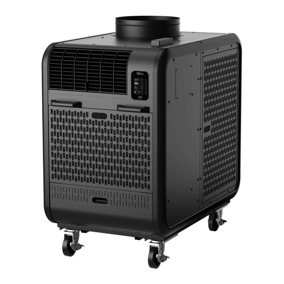
Page 10: Names Of Parts
NAMES OF PARTS Condenser Air Outlet Flange Control Panel Cold Air Outlet Grill Service Panel for Pump Handles Service Panel Caster Power Cord Power Cord Holder... - Page 11 NAMES OF PARTS Condenser Filter Side Panel Condensate Pump (Climate Pro K60 & K63) Drain Tank (Climate Pro K36) Drain Tank Cover Front Panel Evaporator Filter...
-
Page 12: Control Panel
CONTROL PANEL OVERVIEW CLIMATE PRO ___ Model Name and Designation MON 12:00 PM MENU SET TEMP Multi-function butt ons Mult Press the butt ons to set the adjacent Pres values on the LCD screen. value MODE Active butt ons will be lit. Activ COOL FAN SPEED... -
Page 13: Home Screen
HOME SCREEN Day/Time MovinCool Connect MON 12:00 PM MENU Menu ROOM Room temperature TEMP SET TEMP Increase set temperature Set temperature Decrease set temperature MODE Mode: COOL Cool/Fan/Schedule Increase fan speed FAN SPEED Fan Speed: AUTO Hi/Mid/Low Decrease fan speed... -
Page 14: Mode Screen
MODE SCREEN HOME > MODE MON 12:00 PM MODE BACK COOL MODE icon This icon is displayed on the HOME screen during COOL MODE operation. COOL FAN MODE icon This icon is displayed on the HOME screen during FAN ONLY MODE operation. SCHEDULE SCHEDULE MODE icon Press the adjacent butt on to go to... -
Page 15: Menu Screen
MENU SCREEN HOME > MENU MON 12:00 PM MENU BACK SETTING icon Press the adjacent butt on to go to the SETTING screen. SETTING (DAY & TIME/DISPLAY/FAN MODE/ TEMP SCALE) SERVICES icon SERVICES Press the adjacent butt on to go to the SERVICES screen. -
Page 16: Setting Screen
SETTING SCREEN HOME > MENU > SETTING DAY & TIME icon MON 12:00 PM Press the adjacent butt on to go to SETTING BACK the DAY & TIME screen. - Daylight saving (ON/OFF) - Select time zone - Auto adjust (ON/OFF) DAY &... -
Page 17: Installation
INSTALLATION PLACEMENT OF THE UNIT WARNING Installation and electrical work must be performed by qualified electrical personnel. Incorrect installation and/or electrical work may cause fire, electric shock, injury, malfunction or water leaks. To avoid explosion or fire: Do not install the unit in a place where flammable gas may generate, flow, gather or leak. Do not install the unit in a place where conductive dust or oil is floating. -
Page 18: Accessories
Condensate Pump Kit Trim Ring Condensate Tank Self-Supported Duct WARNING Use only official accessories and consult your MovinCool dealer or qualified technician for installing accessories to the unit. Non-genuine accessories or incomplete installation may cause fire, electric shock or water leaks. -
Page 19: Typical Installation Options
Option 1: No negative air pressure in the room Operating condition: - Climate Pro K36: 65°F (18°C), 50%RH to 95°F (35°C), 60%RH - Climate Pro K60 & K63: 65°F (18°C), 50%RH to 105°F (41°C), 50%RH Option 2: Negative air pressure in the room Operating condition: - Climate Pro K36: 65°F (18°C), 50%RH to 95°F (35°C), 60%RH... -
Page 20: Plugging In The Unit
PLUGGING IN THE UNIT WARNING Insert the power plug properly into the outlet. Incomplete insertion may cause fi re or electric shock. To avoid fi re, electric shock or malfunction: Do not connect or disconnect the power plug with wet or oily hands. Do not turn the unit on or off by connecting or disconnecting the power plug. -
Page 21: Lcdi (Leakage Current Detection Interrupter) Power Cord
LCDI (Leakage Current Detection Interrupter) POWER CORD Climate Pro K36 has a LCDI to monitor leakage current. Read the instructions printed on the device for proper use and handling. The conductors inside the cord are surrounded by shields, which are not grounded. -
Page 22: External Warning Device Connection
2. Take out the eight (8) screws, and then remove the service panel from the back of the unit. Climate Pro K36 3. Loosen the bott om two (2) screws and take out the other ten* (10) screws. Move the rear panel upward and remove it. - Page 23 EXTERNAL WARNING DEVICE CONNECTION 5. Insert the warning signal wires through the hole in the rear panel and then through the hole in the control box. Recommended wire size: 16 AWG - 22 AWG Flange Terminal Block Hole in the Control Box Hole in the Rear Panel Route of Signal Wires 6.
-
Page 24: External Alarm Device Connection
2. Take out the eight (8) screws, and then remove the service panel from the back of the unit. Climate Pro K36 3. Loosen the bott om two (2) screws and take out the other ten* (10) screws. Move the rear panel upward and remove it. - Page 25 EXTERNAL ALARM DEVICE CONNECTION 5. Insert the alarm signal wires through the hole in the rear panel and then through the hole in the control box. Recommended wire size: 16 AWG - 22 AWG Flange Terminal Block Hole in the Control Box Hole in the Rear Panel Route of Signal Wires 6.
-
Page 26: Initial Settings
“Opt Out” of sharing by contacting us. Please refer to Operation Manual or visit us at www.movincool.com for further information. NEXT START STOP... -
Page 27: Selecting Time Zone
SELECTING TIME ZONE Multi-function buttons Prior to operation, select your time zone. The default time zone is PST (UTC-08:00). CLIMATE PRO Press on the HOME screen. MON 12:00 PM ROOM MENU TEMP SET TEMP MODE COOL FAN SPEED AUTO START STOP Multi-function buttons CLIMATE PRO... - Page 28 SELECTING TIME ZONE Multi-function buttons CLIMATE PRO 3. Press to select DAY & TIME on the SETTING screen. MON 12:00 PM SETTING DAY & TIME DISPLAY FAN MODE TEMP SCALE START STOP Multi-function buttons CLIMATE PRO 4. Press to go to SELECT TIME ZONE screen. MON 12:00 PM DAY &...
- Page 29 SELECTING TIME ZONE Multi-function buttons CLIMATE PRO 5. Select your time zone by pressing then press to save. MON 12:00 PM TIME ZONE The screen returns to the previous screen. SELECTION If you wish to return to the HOME screen, press repeatedly until the HOME screen is displayed.
-
Page 30: Setting Daylight Savings
SETTING DAYLIGHT SAVINGS When daylight savings start or end, set DAYLIGHT Multi-function buttons SAVINGS TIME. CLIMATE PRO Press on the HOME screen. MON 12:00 PM ROOM MENU TEMP SET TEMP MODE COOL FAN SPEED AUTO START STOP Multi-function buttons CLIMATE PRO 2. - Page 31 SETTING DAYLIGHT SAVINGS Multi-function buttons CLIMATE PRO 3. Press to select DAY & TIME on the SETTING screen. MON 12:00 PM SETTING DAY & TIME DISPLAY FAN MODE TEMP SCALE START STOP Multi-function buttons CLIMATE PRO 4. Press to switch to ON. MON 12:00 PM The default sett ing of the DAYLIGHT SAVINGS is OFF.
-
Page 32: Clock Setting
CLOCK SETTING Day and time are synchronized with GNSS (Global Multi-function buttons Navigation Satellite System) clock. If the time is not adjusted automatically, set the clock manually. CLIMATE PRO Press on the HOME screen. MON 12:00 PM ROOM MENU TEMP SET TEMP MODE COOL... - Page 33 CLOCK SETTING Multi-function buttons CLIMATE PRO 3. Press to select DAY & TIME on the SETTING screen. MON 12:00 PM SETTING DAY & TIME DISPLAY FAN MODE TEMP SCALE START STOP Multi-function buttons CLIMATE PRO 4. Press to switch to AUTO ADJUST OFF. MON 12:00 PM The default sett ing of the AUTO ADJUST is ON.
- Page 34 CLOCK SETTING Multi-function buttons CLIMATE PRO 5. CLOCK SETTING is shown on the DAY & TIME screen. Press to go to CLOCK SETTING screen. MON 12:00 PM DAY & TIME DAYLIGHT SAVING AUTO ADJUST CLOCK SETTING START STOP Multi-function buttons CLIMATE PRO 6.
-
Page 35: Removing Securing Tapes And Sheet
REMOVING SECURING TAPES AND SHEET Before starting operation, remove the tapes securing the drain tank cover. Climate Pro 36: - Remove the cardboard placed on and under the tanks. - Remove the packing foam sheets covering the tanks. - Take out the condensate float from the plastic bag. INSTALLING THE DRAIN TANKS Climate Pro 36: Before starting operation, install the tanks. -
Page 36: Operation
OPERATION COOL MODE Multi-function buttons The set temperature range is 65°F - 90°F (18°C - 32°C) CLIMATE PRO Press on the HOME screen. 12:00 PM ROOM MENU TEMP SET TEMP MODE COOL IDLE FAN SPEED AUTO START STOP Multi-function buttons CLIMATE PRO 2. - Page 37 COOL MODE Multi-function buttons CLIMATE PRO 3. Use to change the set temperature. If the set temperature reaches the minimum or MON 12:00 PM ROOM MENU maximum value, MIN or MAX is displayed. TEMP SET TEMP 4. Use to change fan speed (HI, MID, LO). MODE COOL IDLE FAN SPEED...
-
Page 38: Fan Only Mode
FAN ONLY MODE Multi-function buttons CLIMATE PRO Press on the HOME screen. MON 12:00 PM ROOM MENU TEMP MODE FAN IDLE FAN SPEED START STOP Multi-function buttons CLIMATE PRO 2. Press to select FAN on the MODE screen. MON 12:00 PM MODE COOL SCHEDULE... - Page 39 FAN ONLY MODE Multi-function buttons CLIMATE PRO 3. Use to change fan speed (HI, MID, LO). MON 12:00 PM ROOM MENU TEMP MODE FAN IDLE FAN SPEED START STOP Multi-function buttons CLIMATE PRO START 4. To start operation, press on the HOME STOP MON 12:00 PM screen.
-
Page 40: Schedule Mode
SCHEDULE MODE Multi-function buttons CLIMATE PRO Press on the HOME screen. MON 12:00 PM ROOM MENU TEMP SET TEMP MODE COOL FAN SPEED AUTO START STOP Multi-function buttons CLIMATE PRO 2. Press to select SCHEDULE on the MODE screen. MON 12:00 PM MODE COOL SCHEDULE... -
Page 41: Starting Schedule Mode Operation
STARTING SCHEDULE MODE OPERATION Multi-function buttons CLIMATE PRO Press on the SCHEDULES screen to start SCHEDULE MODE operation. Aft er 3 seconds, the MON 12:00 PM SCHEDULES HOME screen will be displayed if no keys are pressed. SCHEDULE: If you wish to cancel starting SCHEDULE MODE operation in those 3 seconds, press on the ALL KEY BUTTONS... - Page 42 STARTING SCHEDULE MODE OPERATION Multi-function buttons CLIMATE PRO 2. "SCHED. COOL" and (KEY LOCK icon) are displayed on the HOME screen when SCHEDULE MODE operation MON 12:00 PM ROOM is running. TEMP SET TEMP Note: Refer to page 45 for sett ing or editing SCHEDULE MODE SCHED.
-
Page 43: Stopping Schedule Mode Operation
STOPPING SCHEDULE MODE OPERATION Multi-function buttons CLIMATE PRO To stop SCHEDULE MODE operation, press and hold for 5 seconds. MON 12:00 PM ROOM TEMP Aft er 5 seconds, the screen below will be shown for 3 SET TEMP seconds. If you wish to continue SCHEDULE MODE operation, press on the screen below in those 3 seconds. -
Page 44: Temporary Stop During Schedule Mode
TEMPORARY STOP DURING SCHEDULE MODE START Multi-function buttons is pressed for an emergency stop or STOP pressed accidentally during SCHEDULE MODE operation, "TEMPORARY STOP: REFER TO OPERATION MANUAL TO CLIMATE PRO RESUME OPERATION" is displayed. To release TEMPORARY STOP, press and hold MON 12:00 PM ROOM TEMP... -
Page 45: Setting / Editing / Viewing Schedule
SETTING / EDITING / VIEWING SCHEDULE Multi-function buttons CLIMATE PRO Press on the HOME screen. MON 12:00 PM ROOM MENU TEMP SET TEMP MODE COOL FAN SPEED AUTO START STOP Multi-function buttons CLIMATE PRO 2. Press to select SCHEDULE on the MODE screen. MON 12:00 PM MODE COOL... - Page 46 SETTING / EDITING / VIEWING SCHEDULE Multi-function buttons CLIMATE PRO 3. To edit or view SCHEDULE MODE operation, press on the SCHEDULES screen. The EDIT/VIEW SCHEDULES MON 12:00 PM SCHEDULES screen is then shown. SCHEDULE: ALL KEY BUTTONS WILL BE LOCKED WHEN SCHEDULE TURNS ON EDIT/VIEW...
- Page 47 SETTING / EDITING / VIEWING SCHEDULE Multi-function buttons CLIMATE PRO Note: If the start or stop time chosen for programs overlaps MON 12:00 PM EDIT/VIEW with any other program, "SETTING TIME ERROR" will SCHEDULES be displayed. Press any butt on to clear the message. P1 P2 P3 P4 P5 Reset program times.
-
Page 48: Clearing Schedule
CLEARING SCHEDULE Multi-function buttons CLIMATE PRO Press on the HOME screen. MON 12:00 PM ROOM MENU TEMP SET TEMP MODE COOL FAN SPEED AUTO START STOP Multi-function buttons CLIMATE PRO 2. Press to select SCHEDULE on the MODE screen. MON 12:00 PM MODE COOL SCHEDULE... - Page 49 CLEARING SCHEDULE Multi-function buttons CLIMATE PRO 3. To clear SCHEDULE MODE operation, press on the SCHEDULES screen. The confi rmation screen is then MON 12:00 PM SCHEDULES shown. SCHEDULE: ALL KEY BUTTONS WILL BE LOCKED WHEN SCHEDULE TURNS ON EDIT/VIEW SCHEDULE CLEAR SCHEDULE...
-
Page 50: Adjusting Brightness
ADJUSTING BRIGHTNESS Multi-function buttons CLIMATE PRO Press on the HOME screen. MON 12:00 PM ROOM MENU TEMP SET TEMP MODE COOL FAN SPEED AUTO START STOP Multi-function buttons CLIMATE PRO 2. Press to select SETTING on the MENU screen. MON 12:00 PM MENU SETTING SERVICES... - Page 51 ADJUSTING BRIGHTNESS Multi-function buttons CLIMATE PRO 3. Press to select DISPLAY on the SETTING screen. MON 12:00 PM SETTING DAY & TIME DISPLAY FAN MODE TEMP SCALE START STOP Multi-function buttons CLIMATE PRO 4. Press to adjust the brightness level and MON 12:00 PM then press to save.
-
Page 52: Fan Mode
FAN MODE The fan mode determines whether the fan continues to Multi-function buttons run or stop when the room temperature reaches the set temperature. The default sett ing is ON. CLIMATE PRO : Fan constantly runs whether the unit is operating in COOL mode or not. - Page 53 FAN MODE Multi-function buttons CLIMATE PRO 3. Press to select FAN MODE on the SETTING screen. MON 12:00 PM SETTING DAY & TIME DISPLAY FAN MODE TEMP SCALE START STOP Multi-function buttons CLIMATE PRO 4. Press to switch to AUTO. MON 12:00 PM The default sett ing of the FAN MODE is ON.
-
Page 54: Changing Temperature Scale
CHANGING TEMPERATURE SCALE TEMP SCALE is only displayed while the unit is not in Multi-function buttons operation. CLIMATE PRO Press on the HOME screen. MON 12:00 PM ROOM MENU TEMP SET TEMP MODE COOL FAN SPEED AUTO START STOP Multi-function buttons CLIMATE PRO 2. - Page 55 CHANGING TEMPERATURE SCALE Multi-function buttons CLIMATE PRO 3. Press to select TEMP SCALE on the SETTING screen. MON 12:00 PM SETTING DAY & TIME Note: TEMP SCALE is only displayed while the unit is not in DISPLAY operation. FAN MODE TEMP SCALE START STOP...
-
Page 56: Key Lock
KEY LOCK Key lock disables all butt ons on the control panel. Multi-function buttons CLIMATE PRO Press on the HOME screen. MON 12:00 PM ROOM MENU TEMP SET TEMP MODE COOL FAN SPEED AUTO START STOP Multi-function buttons CLIMATE PRO 2. -
Page 57: Key Unlock
KEY UNLOCK Multi-function buttons CLIMATE PRO To unlock the keys, press and hold for 5 seconds. MON 12:00 PM ROOM Aft er 5 seconds, the screen below will be shown for 3 TEMP seconds. If you wish to continue KEY LOCK, press SET TEMP on the screen below in those 3 seconds. -
Page 58: Temporary Stop During Key Lock
TEMPORARY STOP DURING KEY LOCK START is pressed for emergency stop or accidentally Multi-function buttons STOP during key lock, "TEMPORARY STOP: REFER TO OPERATION MANUAL TO RESUME OPERATION" is displayed. CLIMATE PRO To release TEMPORARY STOP, press and hold 5 seconds. MON 12:00 PM ROOM TEMP... -
Page 59: Service Information
SERVICE INFORMATION Machine information can be displayed. Multi-function buttons CLIMATE PRO Press on the HOME screen. MON 12:00 PM ROOM MENU TEMP SET TEMP MODE COOL FAN SPEED AUTO START STOP Multi-function buttons CLIMATE PRO 2. Press to select SERVICES on the MENU screen. MON 12:00 PM MENU SETTING... - Page 60 If you wish to see MACHINE RECORDS, MACHINE press STATUS MACHINE RECORDS SCAN THIS QR CODE OR QR CODE ON THE MOVINCOOL Note: UNIT TO ACCESS WEBSITE AND DOWNLOAD SERVICE MANUAL Technical information is available by scanning QR code. START STOP...
- Page 61 SERVICE INFORMATION Multi-function buttons CLIMATE PRO 3. Aft er pressing on the MACHINE INFORMATION screen, MACHINE STATUS screen is displayed. MON 12:00 PM MACHINE If you wish to return to the HOME screen, press STATUS repeatedly until the HOME screen is displayed. 75 F CTS1 54 F...
-
Page 62: Self-Diagnostic Codes
SELF-DIAGNOSTIC CODES Multi-function buttons CLIMATE PRO If a self-diagnostic code is displayed, follow the on-screen instructions. MON 12:00 PM DIAGNOSTIC CODE: HP 2. If CLEAR is shown, press to reset. ERROR TIME The HOME screen will be shown. MON 8:00 AM HIGH PRESSURE PROTECTION IS ACTIVATED Refer to "List of Self-diagnostic codes"... -
Page 63: List Of Self-Diagnostic Codes
LIST OF SELF-DIAGNOSTIC CODES CODE CONDITION SOLUTION Check FA-1, FA-2 connection Alarm device 1 is activated 2. Identify and correct condition causing alarm 3. Press CLEAR butt on to reset Check AL-1, AL-2 connection Alarm device 2 is activated 2. Identify and correct condition causing alarm 3. -
Page 64: Emptying The Drain Tanks
EMPTYING THE DRAIN TANKS Climate Pro K36 has drain tanks. During COOL mode, water accumulates in the drain tanks. When the tanks become full, the self-diagnostic code “FL” is displayed and the unit turns off automatically. Note: If it is necessary to empty the drain tanks before they are full. the unit must be turned off before emptying. -
Page 65: Condensate Pump Kit
Climate Pro K60 and K63 have a condensate pump kit. Before operating the condensate pump, remove the tab (See page 66) and install the outlet hose (See page 67). Climate Pro K36 can have the pump kit installed as an optional accessory. Note: The compressor does not operate while the condensate pump is discharging the water from the reservoir. -
Page 66: Removing The Tab
REMOVING THE TAB Before installing the outlet hose, remove the tab. Turn the unit off and unplug the power cord. 2. Loosen the bott om two (2) screws and take out the other four (4) screws. Move the service panel for pump upward and remove it. Loosen screws (2) 3. -
Page 67: Hose Installation
HOSE INSTALLATION WARNING Installation must be performed by qualified personnel. Incorrect installation may cause fire, electric shock, injury, malfunction or water leaks. Disconnect power before installation. Beware that some residual voltage may remain in the unit after the power is disconnected. There is a risk of electric shock. Climate Pro K60 and Climate Pro K63 have a 20-foot (6 m) outlet hose with a condensate pump. - Page 68 HOSE INSTALLATION When hanging the hose from the ceiling, the maximum height for lift ing the hose vertically depends on the voltage that the unit uses. Check the maximum hose height in the table below. Run the hose on a downward slope at a minimum rate of 1/4 inch (6.35 mm) per foot. 1/4 inch (6.35 mm) taper per foot Outlet Hose CAUTION...
-
Page 69: Testing
TESTING Turn the unit on. 2. Take out the end of the inlet hose from the inlet hole. 3. Pour water into the pump reservoir from the inlet hole. 4. Make sure that the pump starts running and water is drained through the outlet hose. 5. -
Page 70: Maintenance
MAINTENANCE WARNING When performing maintenance or troubleshooting, stop the operation and remove the power plug. If you touch high-voltage or rotating parts, it may cause electric shock or injury. CLEANING AIR FILTERS Clean air filters once a week. If the unit is used in a dusty environment, more frequent cleaning is required. - Page 71 CLEANING AIR FILTERS 4. Open side panel. Unfasten the two wire frames (2) from the clip by moving the two points shown inwards, and then remove fi lter. Clip Wire Frame Filter Wire Frame (2) Filter 5. Clean off the dust with a vacuum cleaner or rinse in cold or lukewarm water. 6.
-
Page 72: Cleaning The Unit
6. Check the exterior of the unit. If dirty, clean with a damp cloth or mild nonabrasive cleaner. If any part requires repair or replacement, contact your MovinCool dealer or qualifi ed technician. Store in a clean and dry environment. -
Page 73: Troubleshooting
TROUBLESHOOTING Review the following before calling your MovinCool dealer or qualifi ed technician. PROBLEM POSSIBLE CAUSE SOLUTION Unit is not connected to power Check connection to mains supply supply. Try plugging it in Main power is off Check circuit breaker is on... -
Page 74: Technical Specifications
TECHNICAL SPECIFICATIONS MODEL NAME CLIMATE PRO K36 Electronic Features Control Programmable Cooling Capacity Rating Conditions: 95°F, 60% RH 36,000 Btu/h Voltage Requirement 208/230V, 1Phase, 60Hz Total Power Consumption 4.3 kW Current Consumption 19.6 amps Electrical Characteristics Recommended Fuse Size 30 amps NEMA Plug Confi... - Page 75 TECHNICAL SPECIFICATIONS MODEL NAME CLIMATE PRO K60 CLIMATE PRO K63 Electronic Features Control Programmable Programmable Cooling Capacity Rating Conditions: 95°F, 60% RH 60,000 Btu/h 60,000 Btu/h Voltage Requirement 208/230V, 1Phase, 60Hz 460V, 3Phase, 60Hz Total Power Consumption 6.6 kW 6.6 kW Current Consumption 30 amps 9.5 amps...
-
Page 76: Data Privacy Disclosure
DATA PRIVACY DISCLOSURE Tracking of Machine Operation Data This Unit is equipped with an embedded module that collects and transmits to us data on the Unit’s operational performance (“Machine Operation Data”), including: 1. Hours of operation 2. Control Panel sett ings 3. - Page 77 CONSUMER RIGHT TO WITHDRAW CONSENT If you no longer wish to consent to our use, collection and disclosure of Machine Operation Data, you may contact us at 1-800-264-9573 or www.movincool.com and we will disable the Machine Operation Data tracking module.
-
Page 78: Warranty Statement
WARRANTY STATEMENT DENSO PRODUCTS AND SERVICES AMERICAS, INC. ("DENSO") warrants its MOVINCOOL products only to the extent stated in its offi cial writt en warranties. Unless otherwise specifi cally provided in writing by DENSO, DENSO warrants to the original end-user that the products shall be free of defects in materials or workmanship and will function in accordance with DENSO's published specifi... - Page 79 DENSO PRODUCTS AND SERVICES AMERICAS, INC. Long Beach, CA 90810 www.movincool.com First Edition: January 2020 P/N: 484007-4920EN...
Need help?
Do you have a question about the Climate Pro K36 and is the answer not in the manual?
Questions and answers
How to turn on to home screen