Movincool OFFICE PRO 12 Service Manual
Hide thumbs
Also See for OFFICE PRO 12:
- Operation manual (76 pages) ,
- Service manual (56 pages) ,
- Specifications (2 pages)
Table of Contents
Advertisement
Quick Links
Download this manual
See also:
Operating Manual
Advertisement
Table of Contents

Related Manuals for Movincool OFFICE PRO 12


Summary of Contents for Movincool OFFICE PRO 12
- Page 1 M A N U A L S E R V I C E O FFICE P RO 1 2...
- Page 2 © 1998 DENSO SALES CALIFORNIA, INC. All rights reserved. This book may not be reproduced or copied, in whole or in part, without the written permission of the publisher. DENSO SALES CALIFORNIA, INC. reserves the right to make changes without prior notice.
-
Page 3: Definition Of Terms
FOREWORD This manual has been published to service the MovinCool Office Pro 12. Please use this service manual only when servicing the Office Pro 12. DEFINITION OF TERMS WARNING: Describes precautions that should be observed in order to prevent injury to the user during installation or unit operation. - Page 5 (condenser) to exhaust exchanged heat to the outdoors. Unlike conventional air conditioners, the MovinCool Spot Cooling System is a spot cooler EVAPORATOR which directs cool air to particular areas or objects.
- Page 6 GENERAL DESCRIPTION...
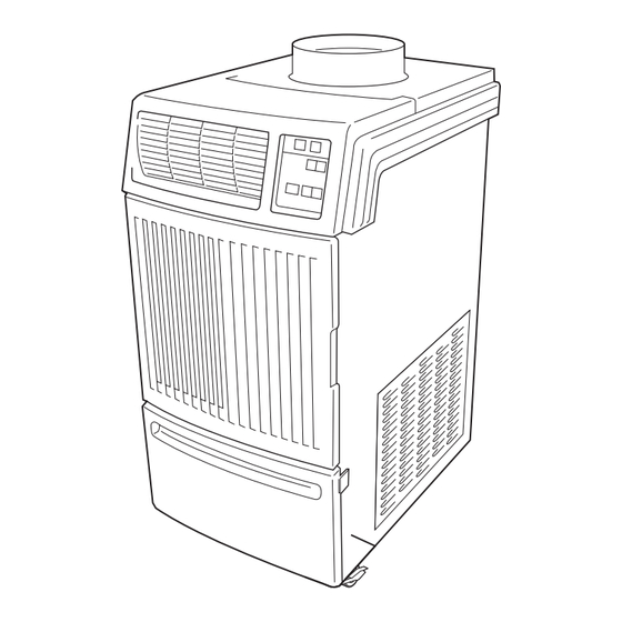
- Page 7 CONSTRUCTION AND SPECIFICATIONS ø11.575 4.60 2.20 12.40 20.67 16.50 27.40 19.30 Exterior Dimensions (units: inches)
- Page 8 CONSTRUCTION AND SPECIFICATIONS 1. Basic Construction The MovinCool Spot Cooling System is compact in construction because the condenser and the evaporator are enclosed in one unit. The interior is divided into three sections. The upper front face is equipped with the evaporator , while the lower front face contains the drain tank.
-
Page 9: Table Of Contents
CONSTRUCTION AND SPECIFICATIONS Rating Conditions dry bulb ..............80 F (26.6 wet bulb ..............67 F (19.4 humidity ..............(50%) Specifications power frequency ........... 60Hz line voltage ............single phase 115 V power consumption ..........1.23 Kw current consumption ..........10.7 Amps power factor ............ - Page 10 CONSTRUCTION AND SPECIFICATIONS EXHAUST AIR VENT COOL AIR VENT EVAPORATOR CENTRIFUGAL FAN CONDENSER CAPILLARY TUBE DRAIN TANK COMPRESSOR DRAIN SWITCH CONTROL BOX Construction of Office Pro 12...
- Page 11 CONSTRUCTION AND SPECIFICATIONS EVAPORATOR FAN CONTROL PANEL TOP PANEL EXHAUST AIR VENT RIGHT HANDLE COOL AIR VENT SIDE PANEL FAN MOTOR FRONT PANEL CONDENSER FAN CAPILLARY TUBE EVAPORATOR COMPRESSOR ACCUMULATOR DRAIN TANK CONDENSER CASTER POWER CORD Construction Diagram...
-
Page 12: Wet Bulb
CONSTRUCTION AND SPECIFICATIONS @ 115V @ 115V 3.6 (14.3) 14 (25.2) 3.2 (12.7) 12 (21.6) 10 (18.0) 2.8 (11.1) 8 (14.4) 2.4 (9.5) 6 (10.8) 2.0 (7.9) Relative Humidity of Inlet Air (%) 35 (95) Cool Air Temperature Difference Curve 30 (86) 25 (77) @ 115V... - Page 13 REFRIGERANT SYSTEM 1. The component parts of the re frigerant system include the following: • Compressor • Evaporator • Condenser • Accumulator • Capillary tube These parts are all connected by copper piping. All the connections have been brazed. EVAPORATOR CONDENSER CAPILLARY TUBE...
-
Page 14: Compressor
REFRIGERANT SYSTEM 2. Compressor The compressor used for the unit is hermetically sealed. The compressor and the compressor motor are in one casing. A. Compressor Construction The construction of a rotary type compressor is divided into two mechanisms. The drive mechanism (compressor motor) and the compression mechanism (compressor). - Page 15 REFRIGERANT SYSTEM 4. Capillary Tube High Temp. / High Press. The capillary tube is a long thin tube and its line Liquid Refrigerant flow resistance serves as an expansion valve. The length and the inner diameter of the capillary tube are determined according to the capacity of refrigeration system, operating conditions and the amount of refrigerant.
- Page 16 REFRIGERANT SYSTEM EVAPORATOR INLET PIPE CONDENSER INLET PIPE COMPRESSOR EVAPORATOR SUCTION PIPE OUTLET PIPE (Insulated) ASSY COMPRESSOR CAPILLARY TUBE DISCHARGE PIPE CONDENSER OUTLET PIPE CONNECTING TUBE (Condenser to Capillary Tube) CONNECTING PIPE (Evaporator to Compressor) Refrigerant System Piping...
- Page 17 Compressor Motor Ground Capacitor for Fan J8 (AUX1) Auxiliary Connector (CPK-3) Capacitor for Compressor AUX2 Auxiliary Connector (not used) RELAY BOARD RELAY BOARD FUSE DIP SWITCH TERMINAL BLOCK COMPRESSOR CAPACITOR CAPACITOR Electrical System and Control Box for Office Pro 12...
- Page 18 ELECTRICAL SYSTEM 1. Basic Operation Of the Office P r o 12 Electrical Circuit There are two basic components used to control the operation of the Of fice Pro 12 Electrical System: • Control Panel Assembly • Control Box The Control Panel Assembly contains the Control Panel, Control Board, inputs for the freeze and room temperature thermisters, drain switch, and a microprocessor .
- Page 19 ELECTRICAL SYSTEM 2. Control Box A. Capacitors The capacitors are used to temporarily boost the power output available to the fan motor and the compressor at start-up. The specifications of each capacitor are Relay Board listed below: Relay Board DIP Switch Fuse CAPACITOR VOLTAGE...
-
Page 20: Output
ELECTRICAL SYSTEM 3. Fan Motor The fan motor is a single phase, induction type two-speed motor . The motor rotates fans on the evaporator side and the condenser side at the same time. Specifications: Rated Voltage: 115 volts 60 hz Rated Output: High –... - Page 21 Off” button. The unit will return to the previous Temperature Set Point. 8. Condensate Pump Kit (optional) The Office Pro 12 model comes standard with a drain tank, which collects the water that forms on the evaporator during normal cooling operation. If the unit is required to operate continuously without periodic emptying of this tank, a condensate pump may be needed.
-
Page 22: Temperature Control
ELECTRICAL SYSTEM 10. Compressor P r otection There is a Time Delay program within the microprocessor . This prevents a heavy load from being applied on the Compressor Motor when restarting the unit (Cool Mode) after a very short period of time. This “delay”... -
Page 23: Troubleshooting Chart
TROUBLESHOOTING AND REPAIR Before troubleshooting the system, the following inspection should be performed. 1. Inspection of Power Source V oltage Check the voltage of the power source. Single phase 115 volts (60Hz) Check the operation and condition of the fuse or circuit breaker in the power source. 2. - Page 24 TROUBLESHOOTING AND REPAIR In case of trouble, perform the following inspection before disassembly. 5. Inspection of Spine Fins To inspect the spine fins of either the evaporator or condenser you must remove the air filters. After removal of the air filters, inspect the spine fins for any dirt, dust, lint, or debris that may have caused poor cooling performance of the unit.
- Page 25 TROUBLESHOOTING AND REPAIR 8. Disassembly Control Panel Top Front Panel Right Handle Upper Rear Panel Right Panel Air Outlet Grille Left Handle Filter Element Front Panel Filter Assy Side Panel Filter Assy Filter Element Room Thermistor Left Panel Blower Housing (evap.) Blower Housing Condenser Fan Drain Pan Assy...
- Page 26 TROUBLESHOOTING AND REPAIR A. Remove drain tank. Removal of Drain Tank B. Remove six (6) screws from upper front panel. Removal of Upper Front Panel Screws C. Slide upper front panel forward and remove. Removal of Upper Front Panel...
- Page 27 TROUBLESHOOTING AND REPAIR D. Louver can be removed from upper front panel by unsnapping it rearward. Removal of Air Outlet Louver E. Remove four (4) screws from service panel. Removal of Service panel Disconnect the three (3) lead wires of the power cord.
-
Page 28: Removal Of Electrical Parts
TROUBLESHOOTING AND REPAIR G. Remove thirteen (13) screws fron rear panel. H. Remove ten (10) screws (eight shown) from upper rear panel and two (2) screws on top. Removal of Back and Upper Rear panel Screws 9 . Removal of Electrical Parts J8 (AUX1) AUX2 IOLF... - Page 29 TROUBLESHOOTING AND REPAIR To Terminal Block Pin #2 Compressor To Fan Motor (R-Terminal) Overload Relay (High Speed) To Fan Motor To Terminal Block Relay Board Ground (Low Speed) (T-Terminal) (not used) DIP Switch Temperature Scale Display Switch ßC ßF Relay Board Fuse Fan Mode Control Switch STOP OPERATE...
- Page 30 TROUBLESHOOTING AND REPAIR 10. Removal of Blower Assembly Control Panel Right Stay Control Panel Left Stay Evaporator Fan Casing Evaporator Fan Motor Stay Middle Frame Sub-Assy Fan Motor Condenser Fan Casing Assy Condenser Fan Ring Sub-Assy Disassembly of Blower...
- Page 31 TROUBLESHOOTING AND REPAIR A. Loosen the set screw using an allen wrench and then remove the centifugal fan. Removal of Centrifugal Fan B. Remove the two (2) nuts as shown. Then remove the blower housing (condenser). Removal of Blower Housing C.
- Page 32 TROUBLESHOOTING AND REPAIR E. Remove seven (7) screws from left side panel. Removal of Screws for Left Side Panel Remove seven (7) screws from right side panel. Removal of Screws for Right Side Panel G. Remove two (2) screws from the control panel stay.
- Page 33 TROUBLESHOOTING AND REPAIR Disconnect the following connectors from the control board: (1) Wire Harness, Relay Board to Control Board J201 (10-pin) (2) Drain Tank Switch J103 (2-pin) (3) Room Temperature Thermister J101 (2- pin) (4) Freeze Thermister J102 (2-pin) NOTE: Mark each of the 2-pin connectors with a different color marker to ensure the correct orienta- tion when they are re-connected.
- Page 34 TROUBLESHOOTING AND REPAIR 13. Inspection of Drain Switch Check for continuity between terminals 1 and 2. TOP OF Continuity should exist. With switch depressed, BASE no continuity should exist between terminals 1 PLATE and 2. If continuity is not as specified above, replace the switch.
- Page 35 TROUBLESHOOTING AND REPAIR 16. Inspection of Wiring Connection Refer to the Wiring Diagrams on page 39 and check for connection of each wire. 17. Inspection of Thermister Using an Ohmeter, check the resistance value across the 2-pin connector. At normal temperature (77˚F (25˚C)) either thermister (room or freeze) should measure approximately 10,000 or 10K ohms.
- Page 36 TROUBLESHOOTING AND REPAIR 19 . Repair of Refrigerant System In case there is a leak, obstruction, or trouble in the refrigerant system of the Spot Cooling System, replace or repair the part in question. After replacing any component all connections must be brazed. A.
- Page 37 TROUBLESHOOTING AND REPAIR Removal of Refrigerant Cycle Components CAUTION 1. Before any refrigerant cycle component can be replaced, it is necessary to recover the refrigerant using standard recovery procedures and equipment. 2. To prevent oxidation, dry nitrogen should be conducted (flow rate 1l/min) through the pinch-off tube during any brazing operation.
- Page 38 TROUBLESHOOTING AND REPAIR 20. Charging the System with R-22 Refrigerant Always ensure that the refrigerant system has been properly evacuated before charging with the specified amount of R-22. WARNING When handling refrigerant (R-22), the following precautions should always be observed: •...
- Page 39 TROUBLESHOOTING AND REPAIR B. Evacuation (1) Open the high pressure valve (HI) and the low pressure valve (LO) of the gauge manifold. (2) Turn on the vacuum pump to start evacuation. (Evacuate the system for approximately 15 minutes.) (3) When the low pressure gauge indicates 750mmHg (30in.Hg) or larger, turn off the vacuum pump and close the high and low pressure valves of the gauge manifold.
- Page 40 TROUBLESHOOTING AND REPAIR (2) Loosen the nut on the gauge manifold side of the charging hose (green). (3) Open the high pressure valve of the gauge manifold. Charge the system with refrigerant until the low pressure gauge indicates 57 PSIG. (4 kg/cm G.) After charging is complete, close the high pressure valve.
- Page 41 TROUBLESHOOTING AND REPAIR (3) Securely place the refrigerant cylinder on a scale with a weighing capacity of 70 lbs (30 kg) that is graduated by 0.2 oz (5 g). (4) Open the high pressure valve of the gauge manifold and the valve of the refrigerant cylinder.
- Page 42 TROUBLESHOOTING AND REPAIR Reassemble the unit in the reverse order of removal. Described below are the parts that require special care in reassembling the unit. Perform all wiring or rewiring as referenced in the wiring diagram. 22. Compressor Mounting Mount the compressor on the frame, using cushions, steel collars, spring washers, plate washers and nuts.
-
Page 43: Troubleshooting And Repair
TROUBLESHOOTING AND REPAIR 26. Schematic... - Page 44 NOTES...
- Page 45 DENSO SALES CALIFORNIA, INC. TECHNICAL SERVICE DEPARTMENT Second Issue: November 1998 First Issue: October 1998 DSCA P/N: LA990009-0435 Printed in USA...
- Page 46 DSCA P/N: LA990009-0435...
Need help?
Do you have a question about the OFFICE PRO 12 and is the answer not in the manual?
Questions and answers